Transcription
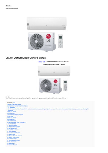
74340a-0921.qrk12/8/00 12:50 PMPage 1Product features and decoration may vary from the picture above.JEEP and the Jeep grille design are registered trademarks of DaimlerChrysler Corporation and are used under license. DaimlerChrysler Corporation.Fisher-Price, Power Wheels by Fisher-Price, BARBIE, Cruisin’ Tunes, Power Lock and Power Stick are U.S. trademarks of Mattel Inc.Owner’s Manual with Assembly InstructionsPlease read this manual and save it with your original sales receipt.For Model 74340Tools needed for assembly: Phillips Screwdriver, Hammer, and Safety Scissors (tools not included).Use only with a Power Wheels 12 Volt Lead-Acid Rechargeable Battery and Power Wheels 12 Volt Chargerwith Type “12V” Connector (included).“Radio” requires three “AA” (LR6) alkaline batteries (not included) for operation.www.powerwheels.com
74340a-0921.qrk12/8/00 12:50 PMPage 2Table of ContentsABCDEFGHIJKLMNOImportant Information . . . . . . . . . . . . . . . . . . . . . . . . . . . . . . . . . . . . . . . . . . . . . . . . . . . . . . . . . . . . . . . . . . . . .2Warnings and Cautions . . . . . . . . . . . . . . . . . . . . . . . . . . . . . . . . . . . . . . . . . . . . . . . . . . . . . . . . . . . . . . . . . . . .3Parts . . . . . . . . . . . . . . . . . . . . . . . . . . . . . . . . . . . . . . . . . . . . . . . . . . . . . . . . . . . . . . . . . . . . . . . . . . . . . . . . .4Parts Diagram . . . . . . . . . . . . . . . . . . . . . . . . . . . . . . . . . . . . . . . . . . . . . . . . . . . . . . . . . . . . . . . . . . . . . . . . . . .6Battery Charging . . . . . . . . . . . . . . . . . . . . . . . . . . . . . . . . . . . . . . . . . . . . . . . . . . . . . . . . . . . . . . . . . . . . . . . . .7Assembly . . . . . . . . . . . . . . . . . . . . . . . . . . . . . . . . . . . . . . . . . . . . . . . . . . . . . . . . . . . . . . . . . . . . . . . . . . . . . .8Label Decoration . . . . . . . . . . . . . . . . . . . . . . . . . . . . . . . . . . . . . . . . . . . . . . . . . . . . . . . . . . . . . . . . . . . . . . . .18Battery Installation . . . . . . . . . . . . . . . . . . . . . . . . . . . . . . . . . . . . . . . . . . . . . . . . . . . . . . . . . . . . . . . . . . . . . .20Battery Care and Disposal . . . . . . . . . . . . . . . . . . . . . . . . . . . . . . . . . . . . . . . . . . . . . . . . . . . . . . . . . . . . . . . .21Rules for Safe Driving . . . . . . . . . . . . . . . . . . . . . . . . . . . . . . . . . . . . . . . . . . . . . . . . . . . . . . . . . . . . . . . . . . . .22How to Operate Your Vehicle . . . . . . . . . . . . . . . . . . . . . . . . . . . . . . . . . . . . . . . . . . . . . . . . . . . . . . . . . . . . . . .23Caring for Your Vehicle . . . . . . . . . . . . . . . . . . . . . . . . . . . . . . . . . . . . . . . . . . . . . . . . . . . . . . . . . . . . . . . . . . .24Problems and Solutions Guide . . . . . . . . . . . . . . . . . . . . . . . . . . . . . . . . . . . . . . . . . . . . . . . . . . . . . . . . . . . . .25Limited Warranty . . . . . . . . . . . . . . . . . . . . . . . . . . . . . . . . . . . . . . . . . . . . . . . . . . . . . . . . . . . . . . . . . . . . . . . .28Authorized Service Centers . . . . . . . . . . . . . . . . . . . . . . . . . . . . . . . . . . . . . . . . . . . . . . . . . . . . . . . . . . . . . . . .28AImportant Information Your new vehicle requires adult assembly. Please setaside at least 60 minutes for assembly. You must charge your battery for 18 - 30 hoursbefore you use your vehicle for the first time. Werecommend that you start charging your battery beforebeginning assembly. Please see Battery Chargingbeginning on page 7 for detailed instructions. Read this manual carefully for important safetyinformation and operating instructions before usingyour vehicle. Keep these instructions for futurereference as they contain important information. This vehicle is designed for use on: grass, asphalt orother hard surfaces; on generally level terrain; by children3 years of age and older. Make sure children know and follow these rules for safedriving and riding:- always sit in the seat.- always wear shoes.- only two (2) riders at a time. This vehicle has adjustable play seat belts. Pleasenote that the adjustable seat belts are designed to bea play feature only and do not function as protectivesafety restraints. To prevent damaging the motors and gears, teach yourchild to stop the vehicle before switching betweenforward and reverse. Do not tow anything behind thevehicle or overload it. Do not exceed the maximumweight capacity of 130 lb. (60 kg). For safety reasons, your vehicle has been pre-set sothat it will only operate at low speed. You must removethe high speed lock-out screw to allow operation ofthe vehicle at high speed. Please see page 24 fordetailed instructions. If you have any questions about your Power Wheels vehicle, please call our toll-free service lines at1-800-348-0751 from 8 AM to 6 PM (EST) Mondaythrough Friday. Trained customer service representativesare available to take your call in English or French.Habla Español? Si usted tiene alguna pregunta ónecesita asistencia llame gratis 1-800-348-0755 para losEstados Unidos. Tenemos representantes que hablanespañol para atender su llamada. For your convenience, Power Wheels maintains anAuthorized Service Center Network with more than400 authorized service centers nationwide. Ourauthorized service centers will repair or replace partsunder warranty at no extra charge, and can performnon-warranty repairs for a minimal charge. Please seethe Authorized Service Center list beginning on page 28to find the authorized service center nearest you, or call1-800-348-0751. Please complete and return the enclosed RegistrationCard today, or call 1-800-348-0751 to register yourvehicle by phone.2
74340a-0921.qrk12/8/00 12:50 PMBPage 3Warnings and CautionsELECTRICAL HAZARDWARNING Battery can fall out and injure a child if vehicle tips over. Always use battery clamp. PREVENT FIRE- Never modify the electrical system. Alterations could cause a fire resulting in seriousinjury and could also ruin the electrical system.- Use of the wrong type battery or charger could cause a fire or explosion resulting inserious injury.- Use of Power Wheels components in products other than Power Wheels vehiclescould cause overheating, fire or explosion. The battery must be handled by adults only. The battery is heavy and contains sulfuricacid (electrolyte). Dropping the battery could result in serious injury. Never allow children to charge the battery. Battery charging must be done by adults only.A child could be injured by the electricity involved in charging the battery. Never lift or carry the battery by the wires or connector. This can damage the battery andpossibly cause a fire resulting in serious injury. Lift and carry the battery by the case only. Read the safety instructions on the battery. Examine the battery, charger and their connectors for excessive wear or damage each timeyou charge the battery. If damage or excessive wear is detected, do not use the charger orthe battery until you have replaced the worn or damaged part. HOT motors. Handle carefully.RIDING HAZARDWARNING Prevent Injuries and Deaths Direct Adult Supervision Required Keep Children Within Safe Riding Areas.These areas must be:- away from swimming pools and other bodies of water to prevent drownings- generally level to prevent tipovers- away from steps, driveways, roads and alleys.CAUTION In the unassembled state, this package contains small parts. Adult assembly is required. Use the charger in dry locations only.3
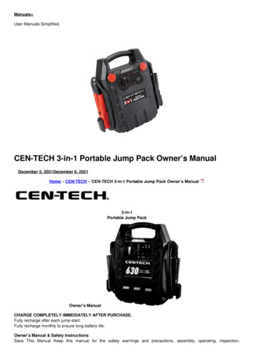
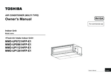
74340a-0921.qrk12/8/00 12:50 PMPage 4CParts If you experience a problem with this product, or are missing a part, please call us at 1-800-348-0751, rather thanreturn this product to the store. Please identify all parts before assembly and save all packaging material until assembly is complete to ensure that noparts are discarded. Metal parts have been coated with a lubricant to protect them during shipment. Wipe all metal parts with a paper towelto remove any excess lubricant.12 Volt ChargerWindshield Bracket - 212 Volt BatteryHeadlight Lens - 2PhoneLight Rack, FrontLight Rack, RearLens Guard - 2Light Cover – 2Long Seat Belt StrapWindshieldHinge Pin - 2SteeringWheel CapShort Seat Belt Strap - 2Taillight Housing SetGas CapBattery Clamp UnitRadioTaillight Lens Set4
74340a-0921.qrk12/8/00 12:50 PMPage 5Parts#6 x 11/2" Screw – 411/2" x 1/4" Machine Screw - 2Key Chain#8 x 1" Screw – 13#10 x 1/2" Screw – 2#8 x 11/4" Screw – 10Key Assembly#10 x 1" Screw – 5.354 Cap Nut – 2*Hood Latch – 2All Shown Actual Size*For your convenience, an extra .354 cap nut has been included.CanopyVehicle BodySteering ColumnWindshield (Back Half)DashSeatSport BarSupport - 2Windshield (Front Half)Steering WheelSport BarBracket SetSport BarHoodNot Shown: Label Sheet - 25
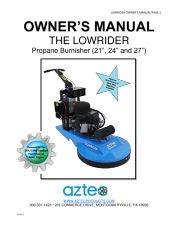
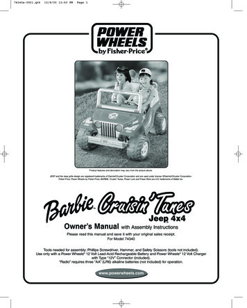
74340a-0921.qrk12/8/00 12:50 PMPage 6DParts 423Note: Some parts shown are assembled on both sides of the vehicle.No. Part12345678910111213Vehicle BodySteering Column.354 Cap NutHood Latch12 Volt BatteryBattery Clamp UnitKey ChainTaillight LensTaillight Housing#8 x 1" ScrewGas CapDash#10 x 1" ScrewQuantity11221112213115No. Part14151617181920212223242526Quantity#10 x /2" Screw#8 x 11/4" ScrewWindshield (Front Half)Windshield (Back Half)RadioKey AssemblySteering WheelSteering Wheel CapSeatLong Seat Belt StrapShort Seat Belt StrapHeadlight LensLens Guard1621011111111222No. ld Hinge PinWindshield BracketSport BarSport Bar SupportSport Bar Bracket#6 x 11/2" Screw11/2" x 1/4" Machine ScrewLight Rack, FrontLight Rack, RearLight CoverCanopyPhone1221224211211
74340a-0921.qrk12/8/00 12:50 PMPage 7EBattery ChargingELECTRICAL HAZARDWARNINGCAUTION Battery can fall out and injure achild if vehicle tips over. Always usebattery clamp. PREVENT FIRE- Never modify the electrical system.Alterations could cause a fire resultingin serious injury and could also ruin theelectrical system.- Use of the wrong type battery orcharger could cause a fire or explosionresulting in serious injury.- Use of Power Wheels components inproducts other than Power Wheels vehicles could cause overheating,fire or explosion. The battery must be handled by adultsonly. The battery is heavy and containssulfuric acid (electrolyte). Dropping thebattery could result in serious injury. Never allow children to charge the battery.Battery charging must be done by adultsonly. A child could be injured by theelectricity involved in charging the battery. Never lift or carry the battery by the wiresor connector. This can damage the batteryand possibly cause a fire resulting inserious injury. Lift and carry the batteryby the case only. Read the safety instructions onthe battery. Examine the battery, charger and theirconnectors for excessive wear or damageeach time you charge the battery. Ifdamage or excessive wear is detected, donot use the charger or the battery until youhave replaced the worn or damaged part.Use the charger in dry locations only.About Thermal FusesYour Power Wheels 12 volt battery is equipped with abuilt-in thermal fuse. The thermal fuse is a self-resettingsafety device which automatically “trips” and shuts downoperation of the vehicle if the vehicle is overloaded or thedriving conditions too severe. Once a fuse has “tripped”,it will automatically reset itself after approximately25 seconds and allow the vehicle to resume normaloperations. To avoid repeated automatic shutdowns, donot overload the vehicle by exceeding the 130 lb. (60 kg).maximum weight capacity or by towing anything behindthe vehicle. Avoid severe driving conditions, such asdriving up very steep slopes or running into fixed objects,which can cause the wheels to stop spinning while poweris still being supplied to the motors. Make sure your childstops the vehicle before switching speeds or direction.If a thermal fuse in a battery continually trips undernormal driving conditions, please contact your localPower Wheels Authorized Service Center. For thelocation of the Authorized Service Center nearest toyou, see page 28.Important Notes7 Your new battery must be charged for at least 18 hoursbefore you use it in your vehicle for the first time. You do not need to remove the battery from yourvehicle to recharge it. The battery must be upright while charging. The charger is not a toy. Do not short circuit the battery. We recommend that you start charging your batterybefore beginning assembly of your new vehicle. Before charging the battery, examine the battery casefor cracks and other damage which may cause sulfuricacid (electrolyte) to leak during the charging process.If damage is detected, do not charge the battery oruse it in your vehicle. Battery acid is very corrosive andcan cause severe damage to surfaces it contacts. Do not charge the battery on a surface which could bedamaged by the acid contained inside the battery. Takeprecautions to protect the surface on which you chargeyour battery. Use only a Power Wheels 12 volt charger with type“12V” connector (120 VAC 60 Hz 28W with an output of12 VDC 1200mA) to charge your Power Wheels rechargeable 12 volt battery.
74340a-0921.qrk12/8/00 12:50 PMPage 8FBattery ChargingAssemblyWARNINGBatteryChildren can be harmed by small parts,sharp edges and sharp points in thevehicle’s unassembled state, or by electricalitems. Care should be taken in unpackingand assembly of the vehicle. Childrenshould not handle parts, including thebattery, or help in assembly of the vehicle.ChargerConnectorIMPORTANT! Assemble the battery retainer unit tothe dash of your vehicle before beginning assemblyof your vehicle. The battery retainer unit must beassembled to the dash before assembling the dashto the vehicle body. Plug the charger connector into the battery. Plug the charger into a standard 120 volt wall outlet .Note: If power flow to the wall outlet is controlled by aswitch, make sure the switch is “ON”. Before first-time use, charge the battery for at least 18hours. Never charge the battery longer than 30 hours. Recharge the battery for at least 14 hours after eachuse of your vehicle. Do not charge the battery longerthan 30 hours. Once the battery is charged, pull firmly on the chargerconnector to disconnect it from the battery. Unplug thecharger from the wall outlet. The battery is now ready tobe installed in your vehicle. Please see the BatteryInstallation section on page 20 for detailed instructions oninstalling your battery. If your battery is already installed inyour vehicle, simply re-connect the motor harnessconnector to the battery and lower and fasten the hood.1ClampBatteryClampUnitDashGrooves Position the dash upside down. Fit the battery clamp unit into the underside of thedash so that the clamp fits into the grooves in the dash.Make sure the battery clamp unit is flush against thesurface of the dash.8
74340a-0921.qrk12/8/00 12:50 PMPage 9Assembly24BatteryClamp UnitBatteryCompartmentBatteryCompartmentDoor Locate the battery compartment door on the back ofthe radio. Loosen the screw in the battery compartment door usinga Phillips screwdriver and lift to open. Insert three “AA” (LR6) alkaline batteries, as indicated inthe battery compartment. To replace the battery compartment door, fit the tabson the door into the slots on the radio. Lower to close.Tighten the screws with a Phillips screwdriver.Do not over-tighten.Note: Do not mix old and new batteries. Do not mix different types of batteries:alkaline, standard (carbon-zinc) or rechargeable(nickel-cadmium). Remove batteries during long periods of non-use.Always remove exhausted batteries from this product.Battery leakage and corrosion can damage thisproduct. Dispose of exhausted batteries safely. Never short circuit the battery terminals. Non-rechargeable batteries are not to be recharged. Only batteries of the same or equivalent type, asrecommended above, are to be used. If removable rechargeable batteries are used, they areonly to be charged under adult supervision. Rechargeable batteries are to be removed from thisproduct before they are charged. Battery chargers used with toys must be examinedregularly for damage to the cord, plug, enclosure andother parts. In the event that such damage is found, thetoy must not be used with the battery charger until thedamage has been repaired. Insert two #10 x 1" screws through the holes in thebattery clamp unit and into the pegs in the entBattery Clamp21.5V x 3“AA” (LR6)1 Position the dash on the vehicle body. Make sure the motor harness connector wire is throughthe groove in the dash. Insert a #10 x 1/ 2" screw through each of the two cornerdash tabs nearest to the passenger compartment. Insert a #10 x 1" screw through the two dash tabsnearest to the battery compartment. Insert a #10 x 1" screw into the hole in the center of thedash, near the battery retainer clip . Tighten the screws with a Phillips screwdriver. Do notover-tighten.9
74340a-0921.qrk12/8/00 12:50 PMPage 10Assembly57223127Radio4Tab15Tab225 268Dash ViewSlotsDash View Fit the tabs on the radio into the slots in the dash. Insert two #8 x 1" screws through the holes in the top ofthe radio and into the dash. Tighten the screws using a Phillips screwdriver.Do not over-tighten.6Phone CordDashPocketKey AssemblyProper label application will help to keep the labelslooking their best! When applying labels, keep thefollowing guidelines in mind: Wash your hands before applying the labels. Before applying the labels, wipe the surface of thevehicle with a clean, dry cloth to remove any dust or oils. Place the labels exactly as shown in the illustrations. For best results, avoid repositioning a label once it hasbeen applied to the vehicle. After applying a label, rub the label firmly with aclean, dry cloth to make sure the label is adheredto your vehicle. Start at the center of a label, andsmooth towards the outer edges to removeair bubbles.T-EndDash View Bend the end of the phone cord so that it forms a “T”. Insert the end of the phone cord through the squareopening in the dash pocket. Pull gently on the cord tomake sure it is secure in the dash. Place the phone in the dash pocket. Snap the key assembly into the dash.10
74340a-0921.qrk12/8/00 12:50 PMPage 11Assembly810SteeringColumnHoleSteering WheelTabCapNutSteeringColumn“UP”Bottom View Wipe the steering column with a paper towel to removeany excess lubricant. Turn the vehicle body on its side. Insert the straight end of the steering column upthrough the hole in the vehicle body wall and outthrough the hole in the dash.9End of Steering Column Turn the vehicle body upright. Position the steering wheel so that the spokes form a“Y” as shown. The tab on the steering wheel stemshould face up. Fit the steering wheel onto the steering column. Fit a cap nut onto the end of the steering column. Tap the cap nut with a hammer to secure it on thesteering column.Hint: You may want the help of another person tosupport the steering column while you tap the cap nutwith the hammer.11Steering WheelSteeringWheel CapSteering RodCap NutBottom View Insert the end of the steering column through the holein the steering rod. Fit a cap nut onto the end of the steering column. While supporting the steering column, tap the cap nutwith a hammer to secure it on the steering column.Hint: You may want the help of another person tosupport the steering column while you tap the cap nutwith the hammer. Fit the steering wheel cap into the center of the steeringwheel with the screw holes aligned. Insert two #8 x 1" screws as shown. Tighten the screws with a Phillips screwdriver.Do not over-tighten.11
74340a-0921.qrk12/8/00 12:50 PMPage 12Assembly1214Wide TabLensHoodLatchHoleWideNotchLens Guard Fit the wide notch in the side of a headlight lens underthe wide tab on a lens guard. Press firmly on the inside of the headlight lens to snap itinto the lens guard. Repeat this procedure to assemble the other headlightlens to the remaining lens guard.13GrilleSlotsHoodLatchHole Insert a hood latch into one of the holes in the vehiclebody, near the hood area. Twist the base of the hood latch 1/4 turn to secure it inthe vehicle body. Repeat this procedure on the other side of the hoodarea to attach the other hood latch to the vehicle body.15TabsHoodSlotTabsSlot Fit the lens tabs on the back of a lens assembly into theheadlight slots in the grille. Press firmly to snap the lens assembly into the grille. Repeat this procedure to snap the other lens assemblyinto the grille. Position the hood over the front of the vehicle bodyas shown. Insert the tabs on the hood into the slots in thevehicle body. Close the hood.12
74340a-0921.qrk12/8/00 12:50 PMPage 13Assembly1716Windshield Frame Front HalfWindshieldBracketsSlotsTabsLip ofBracket Align the slots in the front half of the windshield framewith the tabs on the windshield brackets. Fit the front half of the windshield frame onto thewindshield brackets as shown.Slot18 Fit the screw pegs on the windshield brackets into theholes in the top surface of the dash. Press firmly to fitthe lip on each windshield bracket into the slot in the topof the dash. Insert two #8 x 1" screws into each windshield bracket. Tighten the screws with a Phillips screwdriver. Do notover-tighten.Hinge PinWindshieldFrame Front HalfWindshieldBracket Rotate the front half of the windshield frame down so itlays flat on the vehicle body. Working from the center of the vehicle, insert a hinge pinthrough the holes in the windshield frame and the holesin a windshield bracket, as shown. Repeat this procedure to secure the front half of thewindshield frame to the other windshield bracket.13
74340a-0921.qrk12/8/00 12:50 PMPage 14Assembly1920WindshieldFrame Back HalfShort SeatBelt StrapT-Loop (Pull through slot)Fastener EndEndT-LoopsSlotSlotsSeatSlotWindshield Frame Front HalfSlots Fit the back half of the windshield frame onto the fronthalf of the windshield frame. Make sure the slots at thebottom of the two windshield frame halves are aligned. Insert ten #8 x 11/4" screws into the back half of thewindshield frame. Tighten the screws with a Phillips screwdriver. Do notover-tighten.Hint: Squeeze the two windshield halves together whiletightening the screws. Lift the assembled windshield to the raised position. Turn the seat upside down. Insert the fastener end of a short seat belt strap throughthe slot near the outer edge of the seat. Make sure theside of the seat belt with the fastener faces the outeredge of the seat. Pull the short seat belt strap completely through the slotuntil the last T-loop at the opposite end of the belt catchesagainst the slot. You will pull one T-loop through the slot. Repeat this procedure to assemble the other short seatbelt strap.21Long Seat Belt StrapT-LoopFastener End Insert each fastener end of the long seat belt strapthrough a slot in the center of the seat. Make sure thefasteners face the outer edge of the seat. Pull each side of the long seat belt strap evenly throughthe slots. Make sure to pull each T-loop through a slot. Turn the seat upright.14
74340a-0921.qrk12/8/00 12:50 PMPage 15Assembly2224SeatSeat BackTabsCanopy SleevesCanopySleevesTabsPUSH2 HERESlotCanopy1Sport Bar With the seat at an angle, insert the tabs on the frontedge of the seat into the slots in the foot-well wall. Push down firmly on the edge of the seat above eachtab to snap the tabs into the slots . Position the sport bar on its side so that the sport barends curve away from you. Position the canopy opposite the sport bar with thenetting facing away from you. Slide the four canopy sleeves onto the sport bar. Rotate the back of the seat downto snap the seatback tabs into the slots in the vehicle body. Push downfirmly on the seat back.2523Sport BarCanopy Extend the canopy completely around the sport bar. Insert a #8 x 1" screw into the rear of seat, as shown. Tighten the screw with a Phillips screwdriver. Do notover-tighten.15
74340a-0921.qrk12/8/00 12:50 PMPage 16Assembly2628Sport Bar BracketRingLight Rack Back HalfTabsTunnelSideLegSport BarSport BarSupportLight Rack Front Half Using safety scissors, remove the sport bar brackets fromthe plastic connector. Dispose of the plastic connector. Position the sport bar upright. Fit a sport bar support through a tunnel in a rear cornerof the canopy. Make sure the ring end of the sport barsupport is positioned toward the sport bar. Position a sport bar bracket above one of the sport barside legs, as shown. Fit the ring on the sport bar support against the end ofthe sport bar bracket. Fold the sport bar bracket over the sport bar to close itaround the sport bar and sport bar support.27Sport BarBracket Position the sport bar upright, as shown. Fit and hold the front and back halves of the light rackagainst the sport bar. Make sure the two light rackhalves are aligned, and that the screw holes in the lightrack are aligned with the screw holes in the canopy andthe sport bar. Snap the tabs on the front half of the light rack into theslots below the light housings on the rear half of thelight rack. Insert two #6 x 11/2" screws through the holes in the backof the light rack, through the sport bar, and into the fronthalf of the light rack. Tighten the screws with a Phillips screwdriver. Do notover-tighten.29 Insert a #6 x 11/2" screw into the sport bar bracket. Tighten the screw with a Phillips screwdriver. Do notover-tighten. Repeat steps 26 and 27 to attach the other sport barsupport to the other sport bar side leg.16Light Covers Align the tabs on the inside of a light cover with the slotsin one of the light housings on the light rack. Make surethe light covers are positioned with the wide spaced tabstowards the top. Push firmly on the light cover to snap it to thelight housing. Repeat this procedure on the other side of the lightrack to assemble the other light.
74340a-0921.qrk12/8/00 12:50 PMPage 17Assembly3032Sport #8 x 1" ScrewsPULL HERE Fit the sport bar and sport bar support legs into the holesin the vehicle body. Push down firmly on a sport bar side leg while pullingup on the side fender to fit the sport bar into thevehicle body. Repeat this procedure on the other side of thevehicle body.31 Using safety scissors, remove the taillight lenses and thetaillight housings from the plastic connectors. Dispose ofthe plastic connectors. Face the rear of the vehicle. Fit a taillight lens inside a taillight housing. Position the taillight housing with lens against the vehiclebody with the screw holes aligned, as shown. Insert two #8 x 1" screws through the taillight lens andhousing and into the vehicle body as shown. Tighten the screws with a Phillips screwdriver. Do notover-tighten. Repeat this procedure to attach the other taillight.33Sport BarGas CapTetherRearWheelWell Position the gas cap so that its tether points down. Snap the gas cap into the hole under the right taillight.11/2" x 1/4" Screw Insert a 11/2" x 1/4" machine screw into the hole closestto the front of the vehicle in the underside of the rearwheel well, through the vehicle body and into the endof the sport bar. Tighten the screw with a Phillips screwdriver.Do not over-tighten. Repeat this procedure on the other side of thevehicle body.17
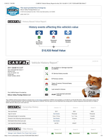
74340a-0921.qrk12/8/00 12:50 PMPage 18GLabel DecorationProper label application will help to keep the labelslooking their best! When applying labels, keep thefollowing guidelines in mind: Wash your hands before applying the labels. Before applying the labels, wipe the surface of thevehicle with a clean, dry cloth to remove any dust or oils. Place the labels exactly as shown in the illustrations. For best results, avoid repositioning a label once it hasbeen applied to the vehicle. After applying a label, rub the label firmly with aclean, dry cloth to make sure the label is adheredto your vehicle. Start at the center of a label, andsmooth towards the outer edges to removeair bubbles.2313127291916201 2420111411116Right Side View3JEEP and the Jeep grille design are registered trademarks ofDaimlerChrysler Corporation and are used under license. DaimlerChrysler Corporation.18 242317211Back View191511013111Left Side View18
74340a-0921.qrk12/8/00 12:50 PMPage 19Label DecorationAfter applying the labels as shown in illustrations 1, 2and 3, apply labels as shown in illustrations 4, 5 and 6to add sparkle to your vehicle.642830Left Side ViewBack ViewOne-time assembly is now complete.IMPORTANT! Please carefully read the owner’s information in thismanual and teach your child about proper vehicleoperation and rules for safe driving before allowingoperation of this vehicle. For safety reasons, your vehicle has been pre-set so thatit will only operate at low speed (21/2 mph, maximum).Make sure that your child can safely operate this vehicleat low speed before removing the high speed lock-outscrew to allow operation of the vehicle at high speed (5mph, maximum). To disconnect high speed lock-out,please see page 24.528Right Side View19
74340a-0921.qrk12/8/00 12:50 PMHPage 20Battery InstallationIMPORTANT! Use only a Power Wheels 12 volt battery.Use of any other battery will damage your vehicle. Makesure that you charge the battery for at least 18 hours usingthe enclosed Power Wheels 12 volt charger beforeoperating your vehicle for the first time. Charge the batteryfor at least 14 hours after each use of the vehicle. Nevercharge the battery longer than 30 hours. Failure to followthese instructions may damage your battery and will voidyour warranty. It is easier to install the battery beforeassembling the
under warranty at no extra charge, and can perform non-warranty repairs for a minimal charge. Please see the Authorized Service Center list beginning on page 28 to find the authorized service center nearest you, or call 1-800-348-0751. Please complete and return the enclosed Registration Card today, or call 1-800-348-0751 to register your