Transcription
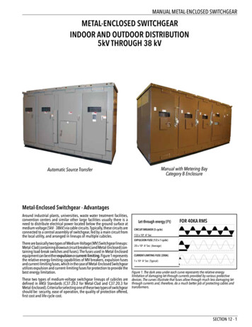
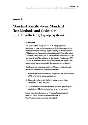
Page 1 of 12Standard SpecificationsMETAL BUILDING SYSTEMSINDEXSection 1:Section 2:Section 3:Section 4:Section 5:Section 6:Section 7:Section 8:Section 9:GeneralStructural DesignBasic Material SpecificationsStructuralRoof and Wall CoveringMiscellaneous Material SpecificationsAccessoriesErectionAnchorage and FoundationsSECTION 1: GENERAL1.1SCOPE1.1.1These specifications cover the materials and the fabrication of building materials manufactured bySunward (“The Company”), which shall be designed and erected in accordance with thesespecifications and accompanying drawings supplied with building materials. Erection by others.1.1.2The material furnished shall include the structural framing, roof panels, wall panels, bracing,fasteners, sealants, flashing, and all other parts for a complete building system (except anchor boltsand all items imbedded in the concrete.) Overhead doors, insulation, etc., are not considered part ofthe building system and should be supplied by others.1.2BUILDING DESCRIPTION1.2.1RIGID FRAME: A structural frame consisting of membersjoined together with moment connections so as to render theframe stable with respect to the design load, without the needfor bracing in its plane. The columns are typically tapered.1.2.2STRAIGHT COLUMN FRAME: They are identical to the Rigidframe as defined in section 1.2.1 except the columns arestraight, not tapered.1.2.3MULTI-SPAN BUILDING: Buildings consisting of more thanone span across the width of the building. Multi-span is a rigidframe as defined in section 1.2.1.Sunward SpecificationsRevised: 9/26/19
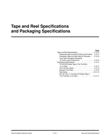
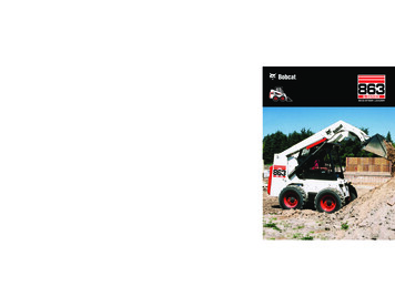
Page 2 of 121.2.4SINGLE SLOPE: Rigid frame is continuous transverse framebuilding with a roof that slopes in one direction. Can be clearspan or multi-span.1.2.5LEAN-TO: A building extension with a roof that slopes in onedirection, getting support from the structure to which it attaches.Main structure must be designed to handle extra load of leanto.1.3BUILDING TERMINOLOGY1.3.1BUILDING WIDTH: The dimension of the building measuredparallel to the main framing from sidewall to sidewall, outside ofby-pass or flush mounted girts.1.3.2BUILDING EAVE HEIGHT: is a nominal dimension measuredfrom bottom of the column base plate to the intersection of theroof and sidewall sheets at the eave strut.1.3.3BUILDING LENGTH: The dimension of the building measuredperpendicular to the main framing from endwall to endwall,outside of by-pass or flush mounted girts.1.3.4BAY: The space between the main frames measured normalto the frame.1.3.5ROOF SLOPE: The tangent of the angle that a roof surfacemakes with the horizontal, usually expressed in units of verticalrise to 12 units of horizontal run.1.4DRAWINGS AND CERTIFICATION1.4.1The Company shall furnish approval erection drawings which include anchor bolts plans, wall androof elevations for framing and sheeting, frame cross sections and general details to show clearlythe proper assembly for all building components. Final erection drawings and shipping list aredelivered with the building, and these drawings are to be used to erect the building.1.4.2A qualified professional engineer shall certify that the building design meets the requirements of thespecifications and conforms to good engineering practices for the loading conditions requested.1.4.3Engineer letter of certification and engineer stamped drawings supplied for each job.1.4.4CERTIFICATIONS: The Company is an approved fabricator with the following certifications:IAS AC472, CSA A660, CSA W47.1, City of Houston, City of Seattle, City of Los Angeles: Type IFabricator, Miami Dade County, Clark County NevadaSunward SpecificationsRevised: 9/26/19
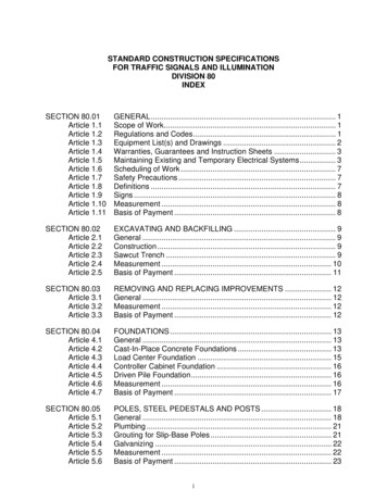
Page 3 of 12SECTION 2: DESIGN2.1 DESIGN STANDARDS, SPECIFICATIONS AND CODESThe following standards, specifications and codes are used in designing metal buildings at the Company.2.1.1STANDARDS:ASCE 7 Standard: American Society of Civil Engineers, Minimum Design Loads for Buildings andOther Structures, Latest Edition.MBMA: Metal Building Manufacturer’s Association, Metal Building Systems Manual, Latest Edition.2.1.2SPECIFICATIONS:Structural Steel: AISC Manual of Steel Construction,Allowable Stress Design, Latest Edition.Structural Joints: AISC specification for structural jointsusing ASTM A325 or ASTM A490 BoltsCold-Formed Steel: AISI Cold-Formed Steel DesignManual, Latest Edition.Welding: AWS (American Welding Society) D1.1 forStructural Steel, AWS D1.3 for Sheet Steel. CSA(Canadian Standard Association) W59 & W47.12.1.3CODES: All model codes, namely IBC and NBC and other applicable state building Codes. (Asoutlined in Section 2.2 code interpretation.)2.1.4BOLTS: As a standard, ASTM A325 (type N) bolts are used as bearing type connections.Occasionally, it may be necessary to use (Type X) bolts. It is ensured that proper checking isdone for this condition. ASTM 307 bolts are used for secondary member connections.2.1.5HIGH STRENGTH BOLTS: ASTM A325 Bolts used on rigid frame moments connections aredesigned as bearing type connections, and threads are included in the shear plane. Turn-of-thenut method is to be used in tightening the high strength moment connection bolts. Specialinspection of the tightening of these bolts is required as specified in building codes.2.1.6WELDING: Welds joining flanges to splice plates, flange to flange, and web butt joints are fullpenetration welds with effective weld throat equal to or exceeding the required strength of thejoint.2.1.7BUILDING WITH OPENINGS: Door and window frames (jambs and headers) are structurallydesigned to replace the wall panels. As per Building Codes “all windows or doors or otheropenings shall be considered as openings unless such openings and their frames are speciallydetailed and designed to resist the loads on elements and components in accordance with theprovisions of this section.” The same assumption is also true for buildings with bi-fold doors andsliding doors provided the manufacturers of these door frames specially design and detail toresist the loads on elements and components for the design wind load.Due to the above assumptions, buildings with truly partial open conditions are designed aspartially enclosed and all other buildings are designed as enclosed or open depending on the“open condition” as defined in the code.2.2CODE INTERPRETATION: Model Code Interpretation and the development of the codecompliance document will be the responsibility of the Engineering Department. All the buildingsare designed per the latest ASCE and MBMA standards. The Company uses the following modelcodes (latest edition or the year applicable for any particular jurisdiction) in designing thebuildings, by using their applicable load combinations:1) International Building Code (IBC)2) National Building Code of Canada (NBC)Any other codes specified for custom designed buildings.Sunward SpecificationsRevised: 9/26/19
Page 4 of 12SECTION 3: BASIC MATERIAL SPECIFICATIONS3.1MATERIAL SPECIFICATIONSGeneral: All materials shall be new and free from defects that would impair their strength or durability.Scope: This specification applies only to Company supplied building materials including framing andbracing, wall and roof cover, connectors and fasteners required for attaching various parts toeach other and to the foundation.The following is a list of materials used in fabrication of the Company’s pre-engineered steel buildings:3.1.2 ROOF AND WALL PANELS:26 & 29 GA: GalvalumePainted24 GA :GalvalumePaintedLiner Panels (29 GA):GalvalumePaintedTrim material:3.1.3 PURLINS, GIRTS, AND EAVESTRUTS:ASTM A792, SS Grade 80, AZ55 Aluminum-Zinc alloy coatedASTM A792, SS Grade 80, AZ50 Aluminum-Zinc alloy coatedASTM A792, SS Grade 50, AZ55 Aluminum-Zinc alloy coatedASTM A792, SS Grade 50, AZ50 Aluminum-Zinc alloy coatedASTM A792, SS Grade 80, AZ55 Aluminum-Zinc alloy coatedASTM A653, SS Grade 80, Galvanized G40ASTM A792, SS Grade 50, AZ50 Aluminum-Zinc alloy coatedASTM A1011 SS or HSLAS, CLASS 1, Grade 553.1.33.1.4 BUILT-UP SECTIONS:Plate:3.1.5 HOT ROLLED SECTIONS:ASTM A36, Grade 36 (Channels)ASTM A992, Grade 50 (Wide Flange Shapes)3.1.6 STRUCTURAL (ROUND) TUBE:ASTM A500B ( FY 42ksi )3.1.7 STRUCTURAL (SQUARE,RECTANGULAR) TUBE:ASTM A500B ( FY 46ksi )3.1.8 BOLTS:WASHERS:3.1.9 ANCHOR BOLTS:ASTM A529 SS, Grade 50 or ASTM A572 HSLA, Type 1or 2, Grade 50Sheet: ASTM A1011 HSLAS, Class 1, Grade 50Bar:ASTM A529 SS Grade 50 or 55 or ASTM A572 HSLAType 1 Grade 50ASTM A325, Type 1 heavy hex bolt with heavy hex nutASTM A563, Grade CASTM A307, Grade A hex bolt with hex nut, ASTM A563 Grade A(All the above items are plain finish)Type 1 ASTM F436 (If Required)½” DIAM. ASTM A307¾” Thru 1 ¼” DIAM. ASTM F1554 GR. 63.1.10 FASTENERS: All self-drilling and self-tapping sheet metal screws will conform to the following:·#12-14 x 1-1/4” Tek 2 or Tek 3 self-drill screw conforms to SAE J78-98 with sealing washer·#12-14 x 1-1/2” Tek 2 or Tek 3 self-drill screw conforms to SAE J78-98 with sealing washer·#12-14 x 1-1/4” #5 Tek 5 self-drill screw conforms to SAE J78-98 with sealing washerSunward SpecificationsRevised: 9/26/19
Page 5 of 12···¼” – 7/8” TAE1 Self-drilling screw conforms to SAE J78-98 with sealing washer#17 x 3/4” Type AB tapping screw conforms to ANSI standard B18.6.4 with sealing washer#10 x 1-1/2” woodgrip screw with sealing washer3.1.11 BRACING:·CABLE:··HILLSIDE WASHER/ BRACER:EYEBOLTS:··ROD:ANGLES:EHS (extra high strength) 7-wire Class A galvanized steel strandconforming to ASTM A475ASTM A48, CL-30 / ASTM 536-84 Grade 65ASTM A572 Grade 55 Rod, Zinc Coated ASTM B633 turnedand welded with ASTM A563 Grade A nut and ASTM F844 WasherASTM A36ASTM A363.1.12 WELDING SUPPLIES:FILLER METAL:FLUX:FILLER METAL:SHIELDING GAS:3.1.13 PRIMER PAINT:Water-Based Red Oxide3.2EM12K Lincoln Weld L-61 (5/64)F7A2 Lincoln Weld 780ER70S-6 Lincoln Weld L-56 (0.045)95 Ar 5 O2 / CO2STRUCTURAL PAINTING3.2.1All structural framing members that are not galvanized shall be cleaned to remove all dirt, grease,oil, and loose mill scale and shall be given one coat of red shop primer.3.2.2 The primer coat thickness shall be a minimum of one mil on primary framing and 0.5 mil onsecondary framing.3.3PANEL PAINTING3.3.1 The finish coat for painted panels, when required, shall be minimum 1 mil thickness silicone film andbaked to a minimum temperature of 435 degrees F. The silicone polyester panels (except white)shall be pigmented with color pigments of a fade resistant type to help ensure long color life. Thepainted panels shall not show excessive chalking, cracking or loss of adhesion during its warrantyperiod.3.3.2 Pre-treating and color coating process shall be applied by a reputable coating firm prior to rollforming. Warranty shall be provided upon request.3.3.3 Colors shall be selected from The Company’s Standard Colors.Sunward SpecificationsRevised: 9/26/19
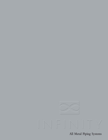
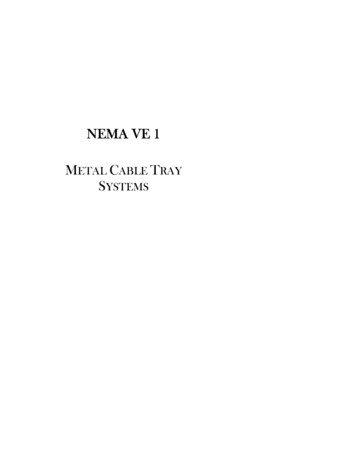
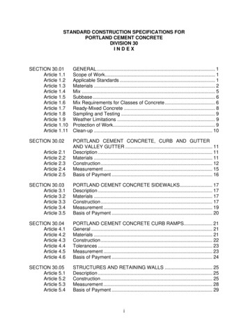
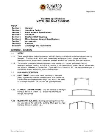
Page 6 of 12SECTION 4: STRUCTURAL4.1.GENERAL4.1.1 All shop welding shall conform to the requirements of the AWS D1.1,and D1.3. Welders shall be fully approved by the proper authorities in bothCanada and the United States. Flange to web welds shall be continuous onone side of web using automatic submerged arc-welding process. All buttwelds shall be full penetration welds.4.1.2 All framing members shall be shop fabricated for bolted held assembly.Bolts shall meet the requirements of the following ASTM Standards, latestissue:4.1.2A-325 for quenched and tempered steel boltsA-307 for steel machine bolts4.1.3 All framing members, where necessary, shall be identified with a piece mark correspondingto the erection drawings.4.2.2. PRIMARY FRAMING4.2.1 All rigid frames shall be welded, built-up “I” sections.4.2.2 All endwall frames and columns shall be either cold-formed, mill rolled, or built up “I” sections,depending on design requirements.4.2.3 All main frame webs, base-plates, splice plates and flanges shall be shop fabricated to includeholes for installation of bolts and slots for bracing.4.3.SECONDARY FRAMING4.3.24.3.14.3.1 Purlins and girts shall be “Z” shaped coldformed sections or “C” shaped cold-formed sectionswith flanges of no less than 2-1/2” and stiffener lips.Purlins shall be considered as continuous beams, lappingeach other at each interior main frame. The girts shall beeither continuous or simple span (flush mounted),depending on type of framing. Purlin and girt overlapshall be 2’-0” to 8’-0” (full lap) depending on designrequirements.4.3.2 Eave strut shall be cold-formed “C” section, formedto appropriate roof pitch (on greater than 1:12).4.3.14.3.3. Framed openings shall be made from sectionsadequate for the specified design loads.4.3.4. A continuous 16 gauge galvanized base angle will be supplied for attachment of the base of thesheeting to the concrete. The base angle will be attached to the concrete slab with ramsets orequivalent anchors (fasteners to concrete not supplied by The Company)4.4.BRACING4.4.1 Diagonal cable bracing (galvanized) or rod bracing shall be used in the roof and walls to removelongitudinal loads from the structure.4.4.2 Portal frames: When special conditions exist so that cable bracing/or rod bracing cannot be used, aportal frame or other type of bracing will be used between frames to remove longitudinal loads.4.4.3 Flange bracing: The inside flange of all main frames shall be braced by angles connecting to theflange and web of the frame and to the web of the purlin or girt so that allowable compression isadequate for any combination of loadings.Sunward SpecificationsRevised: 9/26/19
Page 7 of 124.4.4 To assure consistent purlin spacing and stiffening, purlin bridging angles shall be provided.(1”x1”x16 gauge min).4.4.34.4.24.4.44.4.1SECTION 5: ROOF AND WALL COVERING5.1 PANEL DESCRIPTION5.1.1The Company commercial hi-rib panels shall provide 36” net coverage on walls and roof withlengths up to 34’. The panels shall have 4 major ribs, 12” on center, 1¼” deep. Trapezoidalreturn ribs to taper from 1” to 3-15/16” with intermediate shoulders and an anti-capillary flute(Siphon Groo
CSA (Canadian Standard Association) W59 & W47.1 2.1.3 CODES: All model codes, namely IBC and NBC and other applicable state building Codes. (As outlined in Section 2.2 code interpretation.) 2.1.4 BOLTS: As a standard, ASTM A325 (type N) bolts are used as bearing type connections. Occasionally, it may be necessary to use (Type X) bolts. It is ensured that proper checking is done for this .