Transcription
3D Augmented Reality for Medical ApplicationbyDuc Dang, B.S.A ThesisInElectrical EngineeringSubmitted to the Graduate Facultyof Texas Tech University inPartial Fulfillment ofthe Requirements forthe Degree ofMASTER OF SCIENCESINELECTRICAL ENGINEERINGApprovedDr. Brian NutterChair of CommitteeDr. Sunanda MitraMark SheridanDean of the Graduate SchoolMay, 2016
Copyright 2016, Duc Dang
Texas Tech University, Duc Dang, May 2016ACKNOWLEDGMENTSI express sincere appreciation to my thesis adviser Dr. Brian Nutter for helpingme with precious hints during the whole project, especially during initial phase, wheneverything seem to be so dark and vague. Thanks to my friend Long Phi Nguyen forhis suggestions all through the development of my application. I am also very gratefulto my family for their emotional and financial support because without their help, Iwouldn’t have been able to finish this master’s thesis.ii
Texas Tech University, Duc Dang, May 2016TABLE OF CONTENTSACKNOWLEDGMENTS . iiTABLE OF FIGURES . VABSTRACT . VIICHAPTER 1 INTRODUCTION . 11.Overview of augmented reality . 12.Augmented reality applications . 2a.b.c.3.Education. 2Navigation . 3Medicine. 4Augmented reality summary and thesis objective . 5CHAPTER 2 ANDAR FRAMEWORK . 71.AndAR framework structure . 72.AndAR operation . 83.ARToolkit library . 9a.b.c.4.Marker for AR . 10Marker detection in ARToolkit . 13Transformation matrix estimation in ARToolkit . 14AndAR summary . 17CHAPTER 3 3D HUMAN ANATOMY MODELS AND. COMPUTERIZEDAXIAL TOMOGRAPHY SCAN . 181.3D models. 18a.b.2.Computerized axial tomography (CAT) scan. 24a.b.3.BodyParts3D . 18Wavefront OBJ format . 19Computerized axial tomography scan image . 24Optimizing CAT scan dataset . 263D models and CAT scan summary . 28CHAPTER 4 APPLICATION DESIGN . 291.Application structure . 292.Program operation . 30iii
Texas Tech University, Duc Dang, May 2016a.Program initialization . 31b.Object file reader and object vertex data. 31c.Environment lighting and object material . 32d.Create 3D object . 37e.Create AR object . 37f. Registering AR object to ARToolkit . 38g.Marker detection and transformation matrix estimation . 38h.Rendering 3D AR object . 383.Final result . 44a.b.4.Testing device . 44Final result . 45Application design summary . 48CHAPTER 5 CONCLUSION . 49BIBLIOGRAPHY . 51APPENDIX A DEVELOPMENT ENVIRONMENT . 551.Android OS. 55a.b.c.d.e.2.Linux kernel . 55Libraries . 56Android runtime . 56Android framework . 56Applications layer . 57Development tools and software . 57a.b.Eclipse ADT bundle . 57SketchUp 2015 . 57iv
Texas Tech University, Duc Dang, May 2016TABLE OF FIGURES1 - HUD of an F/A-18C . 12 - Reality-Virtuality (RV) Continuum . 23 - Tokyo Shoseki ‘s AR supported textbook demo on YouTube . 34 - Pioneer AR Heads Up Display device . 35 - Pioneer AR HUD displaying navigation information . 46 - The system uses a transparent display with a tablet positionedbetween the surgeon and the operating field . 57 - Architecture of the AndAR framework . 78 - ARToolKit Architecture . 99 - Example of custom-made marker for ARToolkit . 1010 - Marker images with alphabet characters as patterns . 1111 - Marker "A" and its pattern recognition data file. 1212 – Marker detection steps . 1313 - Marker Coordinate and Camera Coordinate systems in ARToolkit 1414 - Coordinate systems used in ARToolKit . 1515 - u1, u2 and v1, v2 vectors pairs . 1616 - 3D model of left humerus bone in BodyPart3D . 1917 - 3D model of left ulna bone in BodyPart3D . 1918 - Vertex normal vectors of a dodecahedral . 2119 - 3D Cube 2320 - A CT imaging suite . 2521 - A slide of human pelvis CAT dataset . 2622 - Rectangular flat 3D object before and after covering by CATimage . 2723 - Application Block Diagram . 2924 - Application operation flowchart .Error! Bookmark not defined.25 - Vertices coordinates array, Textures coordinates array and vertexNormal array structures . 3226 - A lit and an unlit left humerus bone . 3327 - Examples of rendered 3D model of left humerus bone . 40v
Texas Tech University, Duc Dang, May 201628 - 3D thin flat rectangle object without and with CAT image assurface texture . 4229 - CAT scan images of human pelvis . 4330 - Testing device - LG G Pad 7.0 v400 . 4431 - 3D model of left humerus bone rendered on human body . 4532 - 3D model of left ulna bone rendered inside the left forearm of testsubject . 4633 - 3D model of left radious bone rendered on human body . 4634 – Left and right hip bones rendered on human body . 4735 - T1, T2 and T3 thoracic vertebrae rendered inside the body of testsubject . 4736 - Displaying CAT images of human pelvis on test subject . 4837 - Architecture of Android . 5538 – The test device in this thesis runs Android version 5.0.2, which isbased on Linux kernel version 3.4.0 . 5639 - Eclipse ADT bundle. 5740 - SketchUp 2015 . 57vi
Texas Tech University, Duc Dang, May 2016ABSTRACTAugmented Reality (AR) is a technology that augments user reality withcomputer-generated data such as GPS, audio, video or 3D objects. In comparison withvirtual reality (VR), where the user’s view is totally replaced with a computergenerated environment, Augmented Reality focuses on enhancing a user’s realityexperience with superimposed information. The application of Augmented Reality notonly focuses on military and advertisement applications but also on education andmedicine. This thesis focuses on development of an Augmented Reality application onthe Android platform to view computerized axial tomography (CAT) scan images and3D human anatomy models superimposed over the physical world, displayed on thedevice screen in real time. The developed application is based on the AndARframework, a Java API that provides a foundation to develop Augmented Realityprojects on the Android platform.vii
Texas Tech University, Duc Dang, May 2016CHAPTER 1INTRODUCTION1. Overview of augmented realityAugmented Reality (AR) is a technology that allows live direct view of the realenvironment to be supplemented with computer-generated data. In the context of thisthesis, the term Augmented Reality will be defined with the description made byRonald T. Azuma that AR is a variation of Virtual Reality that has threecharacteristics: combining real and virtual, registering in 3D, and real-time interaction[1]. The typical example of Augmented Reality is the Head-up Display (HUD) infighter pilot’s helmet, where AR is used to display avionic information like airspeed,altitude, horizon line or weapon and sensor data such as weapon status or targetdestination indicator [2]. In Figure 1 is an example of HUD in F/A–18C fighter.Figure 1 - HUD of an F/A-18C [2]1
Texas Tech University, Duc Dang, May 2016Although a variation of Virtual Reality technology, which replaces the realenvironment around a user with a simulated world, an AR system focuses onenhancing the real world with computer-generated or sensed data superimposed uponor composited with it. Figure 2 shows the Reality-Virtuality (RV) Continuumsuggested by Paul Milgram et al [3]. On the two extrema of the continuum are RealEnvironment and Virtual Environment (or Virtual Reality). AR is located in the MixedReality area and inclined to the Real Environment side.Figure 2 - Reality-Virtuality (RV) continuum [3]2. Augmented reality applicationsOne of the first uses of Augmented Reality was in military applications. It isnow applied in numerous field such as education, medicine, navigation, touristinformation, etc.a.EducationIn 2012, Tokyo Shoseki, a Japanese Publisher, produced an AR supportedtextbook that allowed students to see and listen to animated characters on theirtextbooks instead of just reading books (Figure 3).2
Texas Tech University, Duc Dang, May 2016Figure 3 - Tokyo Shoseki ‘s AR supported textbook demo on YouTube [4]b. NavigationAlthough HUD initially appeared in military airplane cockpits, it has beenrecently used in the new generation of automobiles such as Pioneer’s car navigationsystem, introduced at CES 2012 [5]. The navigation system is shown in Figure 4 andFigure 5.Figure 4 - Pioneer AR heads up display device [5]3
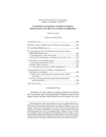
Texas Tech University, Duc Dang, May 2016Figure 5 - Pioneer AR HUD displaying navigation information [5]c. MedicineMedicine is also an area that can benefit from development of AugmentedReality. This technology has been improving healthcare sectors from medical trainingto invasive surgery. Figure 6 shows an excellent example, the System forTelementoring with Augmented Reality (STAR), developed by Dan Andersen and hisfellow researchers at Purdue University and Indiana University. This system allowsremote medical experts to see the patient through a camera, deliver vocal instruction,mark, annotate, zoom in on anatomic regions, and draw lines indicating whereincisions should be made [6]. These instructions will be displayed on the screen of atablet for the operating surgeon. The main application of this system is providingassistance to doctors serving in battlefield areas where surgery expertise is rare [7].4
Texas Tech University, Duc Dang, May 2016Figure 6 - STAR system using a transparent display with a tablet positioned between the surgeon and the operatingfield [6]Recent studies in bones segmentation and extraction also opens newopportunities for the application of AR in the field of medicine. The automatic 3Dbone marrow segmentation framework from researchers of University of Oklahoma[35] and the fully automated spine MRI image segmentation method from Christos G.Bampis et al. [36] show that it is possible to detect, extract and segment relevant partof human spine from PET/CT scans and MRI images automatically. If the orientation,location and label of each part of human spine in medical images could be obtained bya fully automated process, we can use AR technology to integrate relevant informationto each vertebra or render the corresponding 3D vertebra model on it.3. Augmented reality summary and thesis objectiveAs introduced in this chapter, Augmented Reality is a technology that ischanging our lives. By integrating sensed and simulated information to the real5
Texas Tech University, Duc Dang, May 2016environment in real-time, Augmented Reality enhances our current perception ofreality. Although first application of this technology was for the military, teachers,students, and physicians, drivers, and others can now benefit from the capabilities ofAugmented Reality.The goal of this thesis was to build a 3D medical Augmented Realityapplication on the Android platform. The function of application is providing aninteractive way to view computerized axial tomography images and 3D humanskeleton models by superimposing them over the physical world, displayed on mobiledevice screen in real time.6
Texas Tech University, Duc Dang, May 2016CHAPTER 2AndAR FRAMEWORKThis chapter presents a summary about the AndAR framework for AugmentedReality in the Android operating system, which will provide the foundation for theapplication developed in this thesis.AndAR is an Android framework based on the ARToolkit Augmented Realitylibrary created by Tobias Domhan at Baden-Wuerttemberg Cooperative StateUniversity-Stuttgart, Germany [8]. This is an open source library published under theGNU General Public License.This framework provides a pure Java API for Android applicationdevelopment. Under the Java hood, AndAR is powered by the C/C libraries of theARToolkit. These libraries will provide calculating power for marker tracking andtranslation matrices. These C/C libraries can only be accessed through AndAR,Java API, and Java Native Interface (JNI).1. AndAR framework structureThe structure of the AndAR framework can be described by Figure 7:Figure 7 - Architecture of the AndAR framework [8]7
Texas Tech University, Duc Dang, May 2016AndAR uses Android’s Java library to access the camera and generate videoframes. These frames will be passed to the ARToolkit to detect markers, recognizetheir patterns, and calculate camera transformation matrices relative to the detectedmarkers position and orientation.2. AndAR operationThis section will describe the operation of the AndAR framework suggested byTobias Domhan [8]. AndAR uses Java API to access the tablet camera and get thevideo stream. To reduce usage of memory bandwidth, the camera is set to 240x160pixels as default value [8]. The acquired image will be send in 2 sub processes.Sub process 1: The image will be sent to the ARToolkit Library, which willcalculate the transformation matrix for the 3D object. In this step, the ARToolkitlibrary will do marker detection and transformation matrix calculation based on theinput image. These two steps will be explained in the next section. After thetransformation matrix is available, it will be passed back to the main process throughJava Native Interface (JNI).Sub process 2: The image will be converted to an appropriate color space. Theconversion step is necessary because OpenGL ES stores its colors in RGBA format, inwhich each color has Red, Green, Blue, and Alpha components [9], while Androiduses YCbCr format for its images, including video streams [10]. The conversion isprocessed by AndAR [8]:𝐵 1.164 (𝑌 16) 2.018 (𝐶𝑏 128)𝐺 1.164 (𝑌 16) 0.813 (𝐶𝑟 128) 0.391 (𝐶𝑏 128)𝑅 1.164 (𝑌 16) 1.596 (𝐶𝑟 128)After the image is converted to the RGB color space, the resulting image willbe returned to the main process. The converted image will be used as the OpenGLtexture (apply 2D image to 3D environment as texture of a surface). This step includesmaking a full screen preview surface on the device screen to display the video streamfrom the camera. Then, an OpenGL surface will be layered on top of the preview8
Texas Tech University, Duc Dang, May 2016surface. This OpenGL surface will function as a canvas to house a video stream as its2D texture.3. ARToolkit libraryARToolkit was created by Dr. Hirokazu Kato in 1999 [11], developed by theHuman Interface Technology Laboratory (HIT Lab) at the University of Washingtonand currently released as an open-source library by DAQRI, an augmentedreality company. Released under GNU Library General Public License, this library isone of the most popular Augmented Reality libraries, used in thousands of commercialand open source projects [12].Although the ARToolkit structure includes 3 main modules (AR module,Video module and Gsub module), in this thesis, only AR module and Gsub module’stransformation matrix function will be used directly by AndAR [8]. AR module willprovide marker tracking capabilities when the transformation matrix function is usedto calculate relative position and orientation between detected marker and camera. Thestructure of the AndAR framework is shown in Figure 8.Figure 8 - ARToolKit architecture [29]9
Texas Tech University, Duc Dang, May 2016a. Marker for ARThe marker image is essential input for every application based on AndAR andthe ARToolkit library. A marker for ARToolkit can be made by developers with thefollowing constraints [13]: Must be a square marker. Must have a continuous (full black or pure white) border with pattern imageand background with contrasting colors (white background for black pattern or whitepattern image with dark background). The pattern image inside the marker border must be rotationally asymmetric.Figure 9 - Example of custom-made marker for ARToolkit [11]In Figure 9 is an example of custom-made marker for ARToolkit library. Theapplication in this thesis uses markers with alphabet characters as patterns. Thesepatterns were designed in Microsoft Paint as seen in Figure 10.10
Texas Tech University, Duc Dang, May 2016Figure 10 Marker images with alphabet characters as patternsTo detect, recognize, identify and track the marker images from a capturedvideo stream [13], ARToolkit or an application based on ARToolkit must be trainedwith pattern recognition data files (“.patt” files). These “.patt” file are generated frommarker images using ARToolkit Marker Generator Online, an online tool based onAdobe Flash [14].11
Texas Tech University, Duc Dang, May 2016Figure 11 - Marker "A" and its pattern recognition data file12
Texas Tech University, Duc Dang, May 2016b. Marker detection in ARToolkitThe marker detection process inside the ARToolkit can be broken into thefollowing steps [15] (Figure 12): First, the captured live video frame is used to extract a binary image byapplying a threshold to its grayscale image. In the AndAR framework, the binarizationthreshold was set to the value of 100 in the gray scale range of 0-255. Next, ARToolkit will find contours in the image and extract the contours thatfit inside four segments (square). For each of the extracted squares, the pattern inside it will be compared withthe pattern file pre-registered with ARToolkit to find the AR tracking marker. The coordinates of the four vertices of the square and parameters of four linesegments will be saved for estimation of the transformation matrix.Figure 12 – Marker detection steps. [15]13
Texas Tech University, Duc Dang, May 2016c. Transformation matrix estimation in ARToolkitFigure 13 shows the marker coordinate and the camera coordinate systems inARToolkit. To overlay a 3D object on top of a marker, we need to know the relativeposition and rotation between camera and marker and the relationship between MarkerCoordinate and Camera Coordinate systems (Figure 13).Figure 13 - Marker coordinate and camera coordinate systems in ARToolkit [16]Therefore, the transformation matrices that represent the relationship amongCamera Screen Coordinates (xc,yc), Marker Coordinates (XM, YM. ZM) and the CameraCoordinates (XC, YC. ZC) should be estimated (Figure 14). ARToolkit suggestsestimating the intrinsic camera parameter matrix (P) and the image distortion functionbetween Camera Screen Coordinates and Observed Screen Coordinates by doingcamera calibration. However, because the ARToolkit version we are using in thisthesis is integrated into the AndAR framework, which is designed for use withAndroid devices, this calibration step is replaced by loading default camera propertiesstored in the camera parameter file, “camera para.dat” during applicationinitialization. The rest of this section will present the process of transformation matrixestimation in ARToolkit suggested by Kato et al. [11].14
Texas Tech University, Duc Dang, May 2016Figure 14 - Coordinate systems used in ARToolKit [17]The connection between Camera Screen Coordinates and Camera Coordinatescan be expressed by:𝑋𝑐𝑃11 𝑃12ℎ𝑥𝑐𝑌0 𝑃22[ℎ𝑦𝑐 ] 𝑃 [ 𝑐 ] , where 𝑃 [𝑍𝑐0 0ℎ10 01𝑃13 0𝑃23 0]1001The transformation matrices from these marker coordinates to the cameracoordinates (TCM) can be represented by:𝑋𝑐𝑉11𝑉21𝑌𝑐[ ] [𝑍𝑐𝑉3110𝑉12𝑉22𝑉320𝑉13 𝑊𝑥𝑋𝑚𝑋𝑚𝑋𝑚𝑉23 𝑊𝑦𝑉3𝑥3 𝑊3𝑥1 𝑌𝑚𝑌𝑚𝑌][ ] [] [ ] 𝑇𝑐𝑚 [ 𝑚 ]𝑍𝑚𝑍𝑚𝑍𝑚0001𝑉33 𝑊𝑧11101(*)In addition, we have parameters of one pair of parallel sides of a square markerfrom the previous marker detection step:15
Texas Tech University, Duc Dang, May 2016𝑎1 𝑥𝑐 𝑏1 𝑦𝑐 𝑐1 0𝑎2 𝑥𝑐 𝑏2 𝑦𝑐 𝑐2 0Thus, equations of the planes that include these two sides can be representedby:𝑎1 𝑃11 𝑋𝑐 (𝑎1 𝑃12 𝑏1 𝑃22 )𝑌𝑐 (𝑎1 𝑃13 𝑏1 𝑃23 𝑐1 )𝑍𝑐 0𝑎2 𝑃11 𝑋𝑐 (𝑎2 𝑃12 𝑏2 𝑃22 )𝑌𝑐 (𝑎2 𝑃13 𝑏2 𝑃23 𝑐2 )𝑍𝑐 0From this equation, we can compute normal vectors (n1 and n2) of theseplanes:𝑛1 (𝑎1 𝑃11 , 𝑎1 𝑃12 𝑏1 𝑃22 , 𝑎1 𝑃13 𝑏1 𝑃23 𝑐1 )𝑛2 (𝑎2 𝑃11 , 𝑎2 𝑃12 𝑏2 𝑃22 , 𝑎2 𝑃13 𝑏2 𝑃23 𝑐2 )Then, direction vector u1 of two parallel sides is calculated with the productu1 n1 x n2. The directional vector u2 of the two other parallel sides can be calculatedwith the same method.Figure 15 - u1, u2 and v1, v2 vectors pairs [11]However, image processing inaccuracies mean that the vectors won't beexactly perpendicular. Therefore, a pair of perpendicular unit direction vectors v1 andv2 in the plane that includes u1 and u2 will be used instead (Figure 15). From v1 and v2we can calculate the perpendicular direction vector to v1 and v2:v3 v1 * v2From v1, v2, and v3, we now can obtain the rotation component V3x3 in thetransformation matrix TCM:16
Texas Tech University, Duc Dang, May 2016V3x3 [v1t v2t v3t]To calculate translation component w1, w2, and w3 in TCM, we simply solve thesystem of equations (*) by substituting coordinates of four vertices of the detectedmarker in camera screen coordinate system and marker coordinate system.4. AndAR summaryAs presented in this chapter, AndAR was chosen to be the foundation of the3D Augmented Reality application. Its Java API and ARToolkit libraries provide theframework, marker detection and transformation matrices calculation ability neededfor the development process. The design of markers used in this thesis was introducedin this chapter.17
Texas Tech University, Duc Dang, May 2016CHAPTER 33D HUMAN ANATOMY MODELS ANDCOMPUTERIZED AXIAL TOMOGRAPHY SCAN3D Human Anatomy models and Computerized Axial Tomography (CAT)scans are key components in this thesis. These are two elements that will besuperimposed over the human body, displayed on the device screen in real time. Inthis chapter, a brief summary of 3D file format that is used for the application will beintroduced. The CAT scan dataset and its optimization to work with the developedapplication will also be presented.1.3D modelsa.BodyParts3DIn the field of human anatomy, many methods can be used to representanatomical knowledge, and one of the most efficient and convenient is to specifyhuman body parts by 3D models. Thus, we can obtain both computable andcomprehensive representation of a physical human body [18]. Several efforts havebeen made by research groups around the world to publish a 3D human anatomy atlas,such as National Library of Medicine’s Visible Human Project and the BodyParts3Dproject. Among these atlases, BodyParts3D, a 3D anatomy atlas funded by TheIntegrated Database Project, Ministry of Education, Culture, Sports, Science andTechnology of Japan [18], provides a suitable database of 3D human body model forthis thesis. The BodyPart3D is a high resolution “dictionary-type database for anatomyin which anatomical concepts are represented by 3D structure data that specifycorresponding segments of a 3D whole-body model for an adult human male” [18].This database is made freely available under a Creative Commons Share-Alikelicense, which means that the models can be used and altered without charge under therequirement that the alternate version is also distributed under the same license. The18
Texas Tech University, Duc Dang, May 20163D models used in this thesis can be downloaded through the BodyParts3D project ftpsite: ftp://ftp.biosciencedbc.jp/archive/bodyparts3d/ [31] in Wavefront’s .OBJ format.Figure 16 - 3D model of left humerus bone in BodyPart3DFigure 17 - 3D model of left ulna bone in BodyPart3Db.Wavefront OBJ formatThe .OBJ is a geometry definition file format first developed by WavefrontTechnologies (now Alias Systems, part of Autodesk Corporation) for its AdvancedVisualizer 3D graphics software package in the 1980s [19]. Currently, the .OBJ fileformat is widely accepted by other vendors to represent 3D graphic.The application in this thesis supports parts of the .OBJ file format and itssupport material template library (.MTL) file format, which is used in 3D models ofthe BodyPart3D database and in the limited scope of this thesis. Those parts of .OBJand .MTL file formats that are used in the thesis will be described below. The fulldescription of the .OBJ file format can be found in Wavefront’s Advanced VisualizerManual [20].19
Texas Tech University, Duc Dang, May 2016i.OBJ file formatThe .OBJ objects file is written in ASCII to define polygonal objects and theirpoints, lines and faces.The objects used in this thesis have the following file structures:GroupingRenderattributesVertex dataVertex dataElementsElementsFigure 18 - OBJ file structure ofBodyPart3D models Figure 19 - Obj file structure of objectfile used to display CAT imageVertex data will provide coordinates fo
Eclipse ADT bundle. 57 b. SketchUp 2015 . 57 . Texas Tech University, Duc Dang, May 2016 v . virtual reality (VR), where the user's view is totally replaced with a computer-generated environment, Augmented Reality focuses on enhancing a user's reality . displayed on mobile device screen in real time. Texas Tech University, Duc .