Transcription
Probing softwareLATHE WORKPIECE MEASUREMENT SOFTWARE MANUALDEVELOPED FOR HAAS CONTROLSPROGRAMMING MANUAL
IDENTIFICATION DATAManufactured byMARPOSS U.S.A.Address3300 Cross Creek Parkway, Auburn Hills. MISoftware TypeMida Probing: LathesFunctionLathe workpiece measurement Software Manual developed forHaas controlsManual Code:IssuedMay 2018Edition(--)MARPOSS U.S.A. is not obliged to notify customers of changes to the product.The descriptions in this manual in no way authorize tampering by unauthorized personnel. Copyright Marposs USA. 20182
The Marposs supply consists of an IT support containing the software and relativedocumentation (referred to below as "the Product").The Product was developed for users with knowledge and skills in the use of softwareapplications for machine tools, referred to below as "the User".The Product is protected by Marposs copyright. The company reserves the right to makeany changes considered necessary to any part of the Product in order to improve it.Marposs also reserves all rights relative to the Product with reference to modifications andprocessing on board the CNC or other data processing systems, as well as with referenceto any form of transmission and reproduction. Transmission and reproduction are onlyallowed after obtaining express authorization to use the Product on multiple units. Anypersons breaching the above conditions will be prosecuted.The measuring cycles are programmed for the acquisition/processing of measuring datagenerated by Marposs contact or laser probing systems. The cycles can be adjusted tospecific application requirements directly on board the machine. The User must:1. check that the parameters used in the cycles are compatible with the other machinefunctions;2. check that the parameters are not changed or overwritten during execution of machineprograms, causing malfunctions or dangerous situations;3. not change the conditions for use of the cycles by changing the CNC operating modes.The Product has been thoroughly tested. However, Marposs shall not be liable for thecompleteness and accuracy of data. When using the Product for the first time, the Usermust test the Product block by block, to confirm that it conforms for the specific application.After start up, the User must record the parameters and addresses substituted and anychanges made, indicating the changes in the documentation. The software must beconsidered a semi-finished product to be integrated in the machine tool design, and assuch Marposs cannot be held responsible for any damage to the machine resulting from:1. incorrect use of the Product or programming errors,2. Product changes or application faultsInstallation in the machine CNC implies acceptance of the above conditions andacknowledgement of the possible exclusion of the warranty in the event of damage.3
PrefaceDue to the growing popularity of “On Machine Probing” Marposs USA. has developed anew software package for their Mida Machine Tool Touch Probe Systems. This new andinnovative software package was designed to help facilitate the use of Mida probe systemson a wide variety of machine tools.As you incorporate these user-friendly software cycles into your manufacturing processesyou will understand the importance of your completed single or multi spindle cell or systemor a Machine with Y axis capability.By implementing Mida probes and software with a machine tool cell or system you havethe Productivity to profit.This manual details Marposs’ Multi-Purpose Productivity Cycles designed for MidaMachine Tool Touch Probe Systems.4
Manual ContentsChapter 1 – Getting StartedA. Measurement Software CharacteristicsB. Programs by machine configurationC. Probe preparation and testingChapter 2 – X, Z Machine Configuration ProgramsA. Calibrating the X axis, O9201B. Calibrating the Z axis, O9202C. Protected Positioning cycle, O9211D. Single touch in X, O9212E. Single touch in Z, O9214F. Diameter in X, O9216G. Measuring grooves or ribs in Z, O9218H. Measuring grooves or ribs in X, O9226Chapter 3 – X, Z, C Machine Configuration ProgramsA. Diameter in X with center search in C axis, O9221B. Measuring width in Z with center search in C axis, O9222C. Center search with C axis movement, O9223Chapter 4 – X, Y, Z, C Machine Configuration ProgramsA. Calibrating the Y axis, O9203 and O9204B. 3-point diameter calibration, O9205 and O9206C. Calibrating the XY or YZ axis angle, O9207 and O9208D. Single touch in Y axis, O9213E. 3-point diameter measurement, O9215 and O9225F. Diameter in Y axis, O9217 and O92185
Chapter 1 – Getting StartedA. MEASUREMENT SOFTWARE CHARACTERISTICS The approach of the probe to the workpiece is "protected": if an unexpected collision occursbefore the contact touches the workpiece, and the software generates an alarm that interruptsall the movements. Each macro contains a detailed description of all the variables used as inputs and outputs, incomment format. The modal instructions are reset at the end of each cycle. Both the required and optional parameters for each measurement Macro are check to makesure that the values programmed by the user are consistent. If the required inputs have notbeen programmed at the moment they are called up by the Macro, an alarm message isgenerated on the CN display and the measurement cycle is blocked. The software includes a series of alarm messages that warn the operator about every faultcondition that occurs during the measurement Macro; whenever one of these messages isgenerated it causes all the machine axes to stop immediately. It is possible to calibrate up to four separate probes on the turret.Every measurement Macro has the following functions:1. Tolerance check (programmable).2. Workpiece origin settings.3. Printing and transmitting measured data via RS232, PCMCIA card, or USB memory stick.4. Tool compensation (programmable).6
B. Programs by machine configurationUpload the measurement software into the control For 2 axis (X, Z) lathe upload 9201, 9202, 9211, 9212, 9214, 9216, 9218, 9226, 9235, 9236,9241, 9242, 9243, 9244, 9251, 9260, 9261, 9264, 9265, 9266 For 3 axis (X, Z, C) lathe upload 9201, 9202, 9211, 9212, 9214, 9216, 9218, 9221, 9222,9223, 9226, 9235, 9236, 9241, 9242, 9243, 9244, 9251, 9260, 9261, 9264, 9265, 92664 For 4 axis (X, Z, C, Y) lathe upload 9201, 9202, 9203, 9204, 9205, 9206, 9207, 9208, 9211,9212, 9213, 9214, 9215, 9216, 9217, 9218, 9221, 9222, 9223, 9225, 9226, 9235, 9236, 9241,9242, 9243, 9244, 9251, 9260, 9261, 9264, 9265, 9266C. Probe Preparation and Testing Check that the workpiece probe (mounted on the turret) has been installed correctly Check that the batteries have been installed correctly. Check that the receiver and transmitter have a clear path of communication. Test the probe on the turret. This test refers to a probe with optical signal transmission. Activate the probe in MDI using the activation M-code. Insert the following instructions block in MDI mode: G31 U–1. F5. If it functions correctly, the probe should move 1” Repeat the above point, deflecting the stylus manually during the movement, the probeshould stop immediately. If the probe does not behave correctly, contact the MARPOSS installation technicianfor technical support. Set tool geometry for probe Align the stylus (optional)7
Chapter 2 – X, Z Machine Configuration Programs8
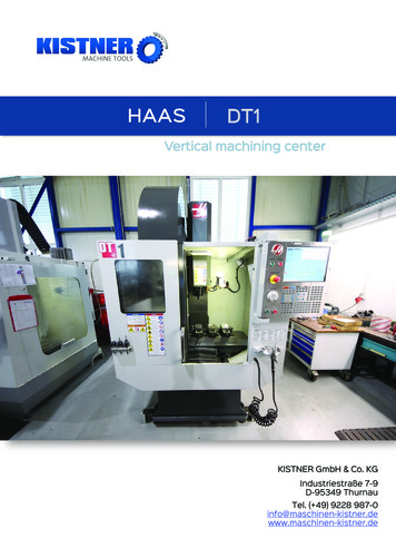
A. CALIBRATING THE X AXIS (O9201)Call up format: G65 P9201 [X] [S] [D] [K] [C] [M]This cycle is used for calibrating the probe in the X axis. The calibration may be performed in onedirection only (Radius) or in both directions (Diameter). Either a ring (O.D.) or a cylinder (I.D.)may be used as a calibration master, provided its dimensions are known.Start position:- SINGLE TOUCH:The probe must be positioned in the X axis so that spherical feeler touches the calibration masteron the correct side (X or X–). The probe must be positioned in the Z axis so that the sphericalfeeler is at the desired touch depth. Alternatively, the cycle positions the probe automatically atthe depth programmed at the input "K".- ID:The probe must be positioned at the center of the calibration master X axis. The probe must bepositioned in the Z axis so that the spherical feeler is at the desired touch depth. Alternatively,the cycle positions the probe automatically at the depth programmed at the input "K".- OD:The probe must be positioned at the center of the calibration master X axis. The touch depthmust be programmed via the input "K".FINAL POSITION:The X and Z axes are returned to the start position.REQUIRED INPUTS:[X] nominal X dimension. (single touch only)[S] select the master type: S 1. for ID, S 2. for OD. If this input is omitted,SINGLE TOUCH calibration is selected automatically.[D] Calibration master diameter, required only if "S" 1 or 2, do not enter this value "S" isomitted.OPTIONAL INPUTS:[K] (optional, used for OD calibration) Z touch depth. If this input is omitted it is assumed that theprobe is already in the correct position.[C] calibration data location [default: 1.-- from 1. to 3.][M] measurement area (centered on the nominal position). MUST BE A POSITIVE VALUE.HAAS CNC AND HAAS COMPATIBLE CONTROL11
BEFORE USING THIS MACRO:The tool compensation for the probe must be active. The tool geometry should be defined withfrom the center of the sphere for the X axis, and from the center or the edge for the Z axis.EXAMPLE 1: Single X Axis CalibrationG28 U0W0T0101G98G31 X2.75 Z - 0.25 F100G65 P9201 X 2.25G28 U0 W0G99M30(Call the turret probe - activate offset)(Feed Per Minute)(Position the probe for single axis touch)(Probe Single Axis Calibration Routine)(Feed Per Revolution)This example call to the X Axis Calibration Cycle probes the X2.25 axis dimension of the calibrationtarget. A single axis touch is made, the direction of the measurement depends on the startingposition of the probe.TIPSEXAMPLE 2: Diameter X axis ID CalibrationIf you don’thave aG28 U0W0T0101(Call the turret probe - activate offset)calibrationG98(Feed Per Minute)gauge,G65 P9211 X0. Z1. F100(Position the probe for diameter touch)machine aG65 P9201 D1.15 S1. K-0.23 (Probe Diameter ID Calibration Routine)piece andG28 U0W0measure theG99(Feed Per Revolution)exact diameterM30within 0.0001”.This example calls to the X Axis Calibration Cycle probe’s a true internal diameter of theDo not removecalibration target at a depth of 0.23" from the surface. The given calibration target diameter is the machined1.15"and the ball diameter of the stylus is 0.236".piece from thechuck. Usethismeasurementfor calibrationpurposes.OUTPUT:C1.C2.C3.#561 X #567 X #573 X #562 X-#568 X-#574 X-#563 Y #569 Y #575 Y #564 Y-#570 Y-#576 Y-#565 Z #571 Z #577 Z #566 Z-#572 Z-#578 Z-HAAS CNC AND HAAS COMPATIBLE CONTROL11
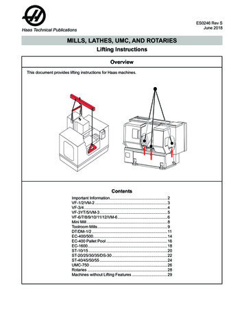
OD Calibration MovementID Calibration MovementHAAS CNC AND HAAS COMPATIBLE CONTROL11
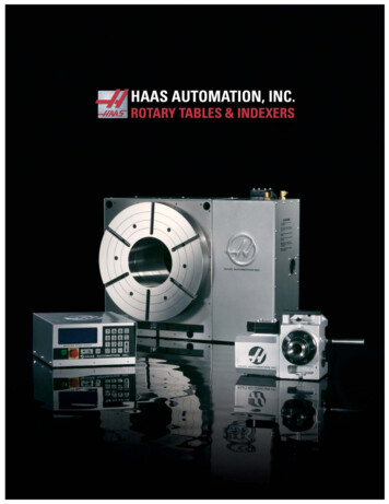
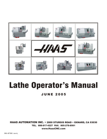
B. CALIBRATING THE Z AXIS (O9202)Call up format: G65 P9202 [Z] [S] [D] [K] [C] [M]This cycle is used for calibrating the probe in the Z axis. The calibration may be performed in onedirection only (Z or Z-) or in both directions (Z and Z-). Tool compensation must be active.Important:The workpiece approach direction depends on the relationship between starting point and the "Z"input corresponding to the calibration master. If the start position on the Z axis is less than thetouch position programmed in "Z", the Z side of the spherical contact is calibrated; otherwise theZ– side is calibrated. The X axis must be aligned with the touch point before calling up thecalibration macro.If it is necessary to calibrate bother sides of the feeler Z and Z– (calibration on a groove) the "Z"input must correspond to the nominal position of the groove Z surface while the diameter of thegroove is defined by the "D" input. If the probe is not already in the touch position, it is positionedautomatically in accordance with the "K" input.Final Position:The X and Z axes are returned to the start positionREQUIRED INPUTS:[Z] nominal master Z dimension.[S] select the master type: S 1. for ID, S 2. for OD. If this input is omitted,SINGLE TOUCH calibration is selected automatically.[D] (calibration on groove/rib only) dimension of the groove (or rib).OPTIONAL INPUTS:[K] touch depth in X. If omitted, it is assumed that the probe is already at the correct touchdepth.[M] measurement area (centered on the nominalposition). MUST BE A POSITIVE VALUE.[C] calibration data location [default: 1.-- from 1. to 3.]HAAS CNC AND HAAS COMPATIBLE CONTROL11
BEFORE USING THIS MACRO:The tool compensation for the probe must be active. The tool geometry should be defined withfrom the center of the sphere for the X axis, and from the center or the edge for the Z axis. Thecalibration master must be mounted on the spindleEXAMPLE 1: Z axis calibrationG28 U0W0T0101G98G65 P9211 X1. Z.5 F100.G65 P9202 Z-0.5G28 U0W0G99M30(Call the probe and activate offset)(Feed Per Minute)(Safe position the probe for single axis touch)(Z axis calibration Routine)(Feed Per Revolution)This example call to the Z Axis Calibration Cycle probes the Z-0.5 nominal, the directionof travel depends on the Z axis starting point.EXAMPLE 2: Z axis groove calibration (double touch)G28 U0W0T0101G98G65 P9211 X1.5 Z.-5 F100.G65 P9211 X1.1 F25.G65 P9202 S1. D.75G98 U0W0G99M30(Call the probe and activate offset)(Feed Per Minute)(Safe positioning)(Safe positioning)(Z axis groove calibration)(Feed Per Revolution)This example uses the Z axis calibration cycle on a groove master (OD) with a between groovedimension of .75 inches. The cycle calibrates both Z and Z- axes.OUTPUTS:C1.C2.C3.#561 X #567 X #573 X #562 X-#568 X-#574 X-#563 Y #569 Y #575 Y #564 Y-#570 Y-#576 Y-#565 Z #571 Z #577 Z #566 Z-#572 Z-#578 Z-HAAS CNC AND HAAS COMPATIBLE CONTROL11
HAAS CNC AND HAAS COMPATIBLE CONTROL11
C. PROTECTED POSITIONING CYCLE (O9211)Call up format: G65 P9211 [X] [Y] [Z] [C] [F]This cycle is designed to position the probe close to the workpiece to be measured beforeexecuting a measurement or calibration macro. Both "Z" and "X" can be programmed (they mayeven be programmed simultaneously). All movements are "protected": if an unexpected collisionoccurs the movement is interrupted and the appropriate error messages appear on the machinedisplay.REQUIRED INPUTS:[X] Absolute position in X.[Y] Absolute position in Y.[Z] Absolute position in Z.[F] Feed rate (default: 1500 mm/min)[C] calibration data location [default: 1.-- from 1. to 3.]Important: C axis cannot be programmedEXAMPLE:G65 P9211 X28.25 Z.8This example uses the protected positioning cycle to move the probe to the programmed point; itis monitored for unexpected collisions throughout the movement.OUTPUTS:Alarms in the event of a collision:PREMATURE X TOUCH DETECTEDPREMATURE Y TOUCH DETECTEDPREMATURE Z TOUCH DETECTEDHAAS CNC AND HAAS COMPATIBLE CONTROL11
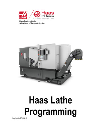
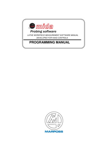
D. SINGLE TOUCH IN X (O9212)Call up format: G65 P9212 [X] [M] [K] [T] [U] [Q] [C] This cycle is used to measure an outside or inside diameter in X with a single touch.At the end of the measurement cycle, the X and Z positions coincide with the start positions.It is possible to modify the tool geometry in X.It is possible to print the data on an outside device.The tolerance control is available.REQUIRED INPUTS:X nominal workpiece dimension in XOPTIONAL INPUTS:[M] measurement area (centered on the nominal position). MUST BE A POSITIVEVALUE.[K] touch depth in Z if omitted it is assumed that the probe is already in position.[T] tool offset to be compensated, X axis.[U] /– workpiece tolerance.[W] work origin to be set, W54-W59 (G54-G59), W54.001-W54.099 (G54.001G54.099) for extended work offsets, W110-W129[Q] print resultsQ if omitted no results are printedQ 1. Print with heading.Q 2. Print without heading.[C] calibration data location [default: 1.-- from 1. to 3.]BEFORE USING THIS MACRO:1) The probe must be in the measurement position.2) Tool compensation must be active.EXAMPLE:G65 P9212 X50. T12. U.025This example uses the single touch cycle in X to measure the workpiece with a nominaldimension of 50mm. The workpiece must be within /– 2mm of the nominal position (50); thetolerance is /– 0.025mm. The offset applied to tool number 12 (X axis), which corresponds to thetool used to process the measured workpiece, is updated according to the measurement. Thecycle is not programmed to print the resultsOUTPUTS:Variable #174 measurement in X.Error with respect to the nominal dimension in variable #175.Alarm message: OUT OF TOLERANCE.Print results (if programmed)HAAS CNC AND HAAS COMPATIBLE CONTROL11
orHAAS CNC AND HAAS COMPATIBLE CONTROL11
E. SINGLE TOUCH IN Z (O9214)Call up format: G65 P9214 [Z] [M] [T] [U] [W] [Q] [C] This cycle is used to measure in Z or Z– with a single touch.The cycle measures the position in Z.It is possible to program the origin shift in Z.It is possible to modify the tool offset in Z.REQUIRED INPUTS:Z nominal workpiece position in Z.OPTIONAL INPUTS:[M] measurement area (centered on the nominal position). MUST BE A POSITIVE VALUE.[T] tool offset to be compensated, Z axis.[U] /– workpiece tolerance.[W] work origin to be set, W54-W59 (G54-G59), W54.001-W54.099 (G54.001-G54.099) forextended work offsets, W110-W129[Q] print resultsQ if omitted no results are printedQ 1. Print with heading.Q 2. Print without heading.[C] calibration data location [default: 1.-- from 1. to 3.]BEFORE USING THIS MACRO:1) The probe must be in the measurement position.2) Tool compensation must be active.3) If the tool start position is less than the nominal position ("Z" input) the measurement isperformed in direction Z . Otherwise it is performed in Z–. The position in X must be such thatit permits contact with the workpiece during the movement in Z.HAAS CNC AND HAAS COMPATIBLE CONTROL11
EXAMPLE:G65 P9214 Z-30.25 T12. U.025This example uses the single touch cycle in Z to measure the workpiece with a nominal dimensionof -30.25mm. The workpiece must be within /– 2mm of the nominal position; the tolerance is /–0.025mm. The offset applied to tool number 12 (Z axis), which corresponds to the tool used toprocess the measured workpiece, is updated according to the measurement. The cycle is notprogrammed to print the results.OUTPUTS:Variable #174 measurement in Z.Error with respect to the nominal dimension in variable #175.Alarm message: OUT OF TOLERANCE.Print results (if programmed)HAAS CNC AND HAAS COMPATIBLE CONTROL11
F. DIAMETER IN X (O9216)Call format: G65 P9216 [D] [S] [B] [M] [K] [T] [U] [Q] [C] [W] [A] This cycle measures an inside or outside diameter with a "touch" in the X axis, aspindle rotation (B), and another “touch” in X axis.It is possible to modify the tool offset in X.At the end of the measurement cycle, the X and Z positions of the axes coincide with the startpositions.REQUIRED INPUTS:D nominal workpiece diameter in X.S select ID – OD.S 1. Inside diameter (ID)S 2. Outside diameter (OD)S 3. Obstructed Inside diameter (ID)S 4. Cylinder Outside diameter (D) for semiOPTIONAL INPUTS:[B] spindle rotation (180-degree default, range of 45-315)[M] measurement area (centered on the nominal position). MUST BE A POSITIVE VALUE[K] touch depth in Z if omitted it is assumed that the probe is already in position[T] tool offset to be compensated, X axis[U] /– workpiece tolerance[Q] print resultsQ if omitted no results are printed.Q 1. Print with heading.Q 2. Print without heading.[C] calibration data location [default: 1.-- from 1. to 3.][W] work origin to be set in X with reference to the center of the measured diameter, W54-W59(G54-G59), W54.001-W54.099 (G54.001-G54.099) for extended work offsets, W110-W129[A] angleBEFORE USING THIS MACRO:1) The probe must be in the measurement position.2) Tool compensation must be active.3) Position the probe at the starting point.4) The X axis must be positioned at the nominal center of the workpiece. The touch depth isdetermined by the "K" input. If this input is omitted it is assumed that the probe is already in themeasurement position.HAAS CNC AND HAAS COMPATIBLE CONTROL11
EXAMPLE:G65 P9216 D63.10 S1. T12. U.025This example measures the nominal inside diameter of 63.10 mm with two touches in X. Themeasurement area is /– 2mm; the tolerance on the diameter is 0.025mm. The offset applied totool number 12 is modified by a value equivalent to the measured error.OUTPUTS:Diameter in X in variable #174.Error with respect to the nominal dimension in variable #175.Center of the workpiece in X in variable #173.Alarm message: OUT OF TOLERANCEPrint results (if programmed)HAAS CNC AND HAAS COMPATIBLE CONTROL11
G. MEASURING GROOVES AND RIBS IN Z (O9218)Call format: G65 P9218 [D] [S] [M] [K] [U] [Q] [C] [W] [R] [A] This cycle is used to measure grooves or ribsREQUIRED INPUTS:D nominal workpiece diameter in X.S select ID – OD.S 1. Inside diameter (ID)S 2. Outside diameter (OD)S 3. Obstructed Inside diameter (ID)S 4. Cylinder Outside diameter (D) for semiOPTIONAL INPUTS:[M] measurement area (centered on the nominal position). MUST BE A POSITIVE VALUE.[K] touch position in X. If omitted it is assumed that the probe is already positioned correctly.[R] shift height distance in X for rib measurements.[U] /– workpiece tolerance.[Q] print resultsQ if omitted no results are printedQ 1. Print with heading.Q 2. Print without heading.[C] calibration data location [default: 1.-- from 1. to 3.][W] work origin to be set in Z and C, with reference to the center of the measured groove/rib, W54W59 (G54-G59), W54.001-W54.099 (G54.001-G54.099) for extended work offsets, W110-W129[A] angleBEFORE USING THIS MACRO:1) The probe must be in the measurement position.2) Tool compensation must be active.3) Position the probe at the start point.4) The probe must be positioned in Z so that it corresponds with the nominal center of the grooveor rib. The touch position in X is determined by the "I" input. If this input is omitted it is assumedthat the probe is already in the measurement position.HAAS CNC AND HAAS COMPATIBLE CONTROL11
EXAMPLE:G65 P9218 D30.25 S1. U.025This example measures a groove (ID) having a nominal dimension of 30.25 mm with two touchesin X. The measurement area is /– 2mm; the tolerance on the diameter is /– 0.025mm. The offsetapplied to tool number 12 is modified by a value equivalent to the measured error.OUTPUTS:Measurement result variable #174.Error with respect to the nominal dimension in variable #175.Center of the workpiece in Z in variable #173.Alarm message: OUT OF TOLERANCEPrint results (if programmed)HAAS CNC AND HAAS COMPATIBLE CONTROL11
H. MEASURING GROOVES AND RIBS IN X (O9226)Call format: G65 P9226 [D] [S] [M] [K] [U] [Q] [C] [W] [R] [A] This cycle is used to measure grooves or ribsREQUIRED INPUTS:D nominal workpiece diameter in X.S select ID – OD.S 1. Inside diameter (ID)S 2. Outside diameter (OD)S 3. Obstructed Inside diameter (ID)S 4. Cylinder Outside diameter (D) for semiOPTIONAL INPUTS:[M] measurement area (centered on the nominal position). MUST BE A POSITIVE VALUE.[K] touch position in X. If omitted it is assumed that the probe is already positioned correctly.[R] shift height distance in X for rib measurements.[U] /– workpiece tolerance.[Q] print resultsQ if omitted no results are printedQ 1. Print with heading.Q 2. Print without heading.[C] calibration data location [default: 1.-- from 1. to 3.][W] work origin to be set in Z and C, with reference to the center of the measured groove/rib, W54W59 (G54-G59), W54.001-W54.099 (G54.001-G54.099) for extended work offsets, W110W129[A] angleBEFORE USING THIS MACRO:5) The probe must be in the measurement position.6) Tool compensation must be active.7) Position the probe at the start point.8) The probe must be positioned in Z so that it corresponds with the nominal center of the grooveor rib. The touch position in X is determined by the "I" input. If this input is omitted it is assumedthat the probe is already in the measurement position.HAAS CNC AND HAAS COMPATIBLE CONTROL11
EXAMPLE:G65 P9226 D30.25 S1. U.025This example measures a groove (ID) having a nominal dimension of 30.25 mm with two touchesin X. The measurement area is /– 2mm; the tolerance on the diameter is /– 0.025mm. The offsetapplied to tool number 12 is modified by a value equivalent to the measured error.OUTPUTS:Measurement result variable #174.Error with respect to the nominal dimension in variable #175.Alarm message: OUT OF TOLERANCEPrint results (if programmed)HAAS CNC AND HAAS COMPATIBLE CONTROL11
Chapter 3 – X, Z, C Machine Configuration ProgramsHAAS CNC AND HAAS COMPATIBLE CONTROL11
I.DIAMETER IN X WITH CENTER SEARCH IN C (O9221)G65 P9221 [D] [S] [M] [K] [U] [Q] [C] [R] [T] [A] [F] [W] This cycle measures an inside and outside diameter calculating them along the rotation axis Cfirst, then using a "double touch" on the X axis (X– and X ).It is possible to modify the tool offset in X.It is possible to set up a working offset in X and C with respect to the determined center.At the end of the measurement cycle, the X and Y positions of the axes coincide with the startpositions.REQUIRED INPUTS:D nominal workpiece dimension in Z.S select ID – OD.S 1. Inside diameter (ID)S 2. Outside diameter (OD)OPTIONAL INPUTS:[M] measurement area (centered on the nominal position). MUST BE A POSITIVE VALUE[K] touch depth in Z if omitted it is assumed that the probe is already in position[T] tool offset to be compensated, X axis[U] /– workpiece tolerance[R] home position in Z [default: start position in Z][Q] print resultsQ if omitted no results are printed.Q 1. Print with heading.Q 2. Print without heading.[C] calibration data location [default: 1.-- from 1. to 3.][A] Angle for C axis [default:30][F] feed rate for C axis[W] work origin to be set, W54-W59 (G54-G59), W54.001-W54.099 (G54.001G54.099) for extended work offsets, W110-W129BEFORE USING THIS MACRO:1) The probe must be in the measurement position.2) Tool compensation must be active.3) Position the probe at the start point.4) The X axis must be positioned in the nominal center of the workpiece. The touch depth isdetermined by the "K" input. If this input is omitted it is assumed that the probe is already in themeasurement position.HAAS CNC AND HAAS COMPATIBLE CONTROL11
EXAMPLE:G65 P9221 D63.10 S1. T12. U.025This example measures the nominal inside diameter of 63.10 mm with two touches in X. Themeasurement area is /– 2mm; the tolerance on the diameter is 0.025mm. The offset applied totool number 12 is modified by a value equivalent to the measured error.OUTPUTS:Diameter in X in variable #174.Error with respect to the nominal dimension in variable #175.Center of the workpiece in X in variable #173.Center of the workpiece in C in variable #172.Alarm message: OUT OF TOLERANCEPrint results (if programmed)HAAS CNC AND HAAS COMPATIBLE CONTROL11
J. MEASURING WIDTH IN Z WITH CENTER SEARCH IN C (O9222)G65 P9222 [D] [S] [M] [K] [U] [Q] [C] [R] [T] [W] [A] [F] This cycle measures a groove or a rib, calculating them along the rotation axis C first, thenusing a "double touch" on the Z axis (Z– and Z ).It is possible to set up a working offset in Z and C with respect to the determined center.At the end of the measurement cycle, the X and Y positions of the axes coincide with the startpositions.REQUIRED INPUTS:D nominal workpiece dimension in Z.S select ID – OD.S 1. Inside diameter (ID)S 2. Outside diameter (OD)OPTIONAL INPUTS:[M] measurement area (centered on the nominal position). MUST BE A POSITIVE VALUE.[K] touch position in X. If omitted it is assumed that the probe is already positioned correctly.[T] tool offset to be compensated, X axis.[U] /– workpiece tolerance.[R] shift height in X for rib measurements. [default: start position in X][Q] print resultsQ if omitted no results are printedQ 1. Print with heading.Q 2. Print without heading.[W] work origin to be set, W54-W59 (G54-G59), W54.001-W54.099 (G54.001G54.099) for extended work offsets, W110-W129[C] calibration data location [default: 1.-- from 1. to 3.][A] Angle for C axis [default:30][F] feed rate for C axisBEFORE USING THIS MACRO:1) Tool compensation must be active.2) Position the probe at the start point.3) The probe must be positioned in Z so that it corresponds with the nominal center of the grooveor rib. The touch position in X is determined by the "I" input. If this input is omitted it is assumedthat the probe is already in the measurement position.HAAS CNC AND HAAS COMPATIBLE CONTROL11
EXAMPLE: G65 P9222 D30.25 S1. U.025This example measures a groove (ID) having a nominal dimension of 30.25 mm with two touchesin Z, after having determined the position of the center along the C rotary axis (using two touches).The default measurement area is /– 3mm; the tolerance on the diameter is /– 0.025mm.OUTPUTS:Dimension measured in Z in variable #174.Error with respect to the nominal dimension in variable #175.Center of the workpiece in Z in variable #173Center of the workpiece in C in variable #172.Alarm message: GROOVE/RIB IN OUT OF TOLERANCEPrint results (if programmed)HAAS CNC AND HAAS COMPATIBLE CONTROL11
K. CENTER SEARCH WITH C AXIS MOVEMENT (O9223)G65 P9223 [S] [C] [A] [F] [J] [K] [R] [W] This cycle determines the position of the center of a diameter in X or Y or a groove/rib in Zalong the C rotary axisIt is possible to set up a working offset in C with respect to the determined center.At the end of the measurement cycle, the X and Y positions of the axes coincide with the startpositions.REQUIRED INPUTS:S select ID – OD.S 1. Inside diameter (ID)S 2. Outside diameter (OD)OPTIONAL INPUTS:[C] calibra
DEVELOPED FOR HAAS CONTROLS PROGRAMMING MANUAL . 2 IDENTIFICATION DATA Manufactured by MARPOSS U.S.A. Address 3300 Cross Creek Parkway, Auburn Hills. MI Software Type Mida Probing: Lathes . For 3 axis (X, Z, C) lathe upload 9201, 9202, 9211, 9212, 9214, 9216, 9218, 9221, 9222,