Transcription
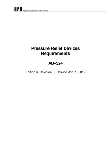
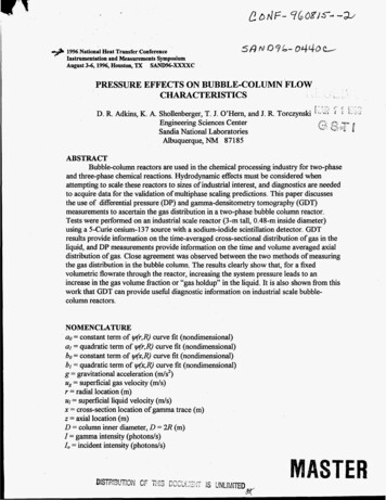
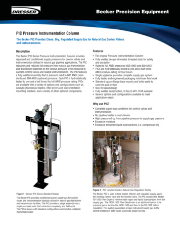
Becker Precision EquipmentPIC Pressure Instrumentation ColumnThe Becker PIC Provides Clean, Dry, Regulated Supply Gas for Natural Gas Control Valvesand InstrumentationDescriptionFeaturesThe Becker PIC Series Pressure Instrumentation Column providesregulated and conditioned supply pressures for control valves andinstrumentation utilized in natural gas pipeline applications. The PICregulates and reduces full pressure from natural gas transmissionand distribution pipelines to the various pressure levels required tooperate control valves and related instrumentation. The PIC featuresa fully-welded assembly that is pressure rated to 600 ANSI (standard) and 900 ANSI (optional) pressure. Each PIC is hydrostaticallytested to one and a half times the full ANSI pressure rating. PICsare available with a variety of options and configurations such ascatalytic (flameless) heaters, filter-dryers and instrumentationmounting brackets, and a variety of other optional components. The original Pressure Instrumentation Column Fully welded design eliminates threaded body for safetyand durability Rated to full ANSI pressures (600 ANSI and 900 ANSI) PICs are hydrostatically tested to one and a half timesANSI pressure rating for four hours Single appliance provides complete supply gas system Fully tested and engineered packaging minimizes field work Standard square flange base mounts and bolts easily toconcrete pad or floor Non-threaded design Fully welded construction, X-Ray to API-1104 available Several options and configurations available to meetapplication needsWhy use PIC? Complete supply gas conditions for control valves andinstrumentation No pipeline heater in cold climate High pressure drop from pipeline pressure to supply gas pressure. Excessive moisture Excessive entrained liquid hydrocarbons (i.e. compressor oil)Figure 2 - PIC Installed Inside a Natural Gas Regulation FacilityFigure 1 - Becker PIC Series Standard DesignThe Becker PIC provides conditioned power supply gas for controlvalves and instrumentation typically utilized in natural gas distributionand transmission facilities. The PIC provides a single assembly via asingle purchase order that minimizes complexity and field work.The PIC is shown with standard configuration and includes a catalytic(flameless) heater.The Becker PIC is used to feed heated, filtered, and regulated supply gas tothe working control valve and the monitor valve. The PIC includes the BeckerFD-1500 Filter-Dryer to remove water vapor and liquid hydrocarbons from thesupply gas. The FACD-1500 Filter-Deodorizer is an additional option. Linepressure gas is fed into the FACD-1500 and then to the FD-1500 beforeregulation. This system guarantees proper instrument supply gas to thecontrol systems of both valves to provide longer service.
The Becker PIC Pressure Instrumentation Column is a High Performance, High QualityPower Supply Gas System Packaged in a Single System with Guaranteed PerformanceFlameless Heater Supply Gas RegulatorThe Flameless Heater Supply Gas Regulator regulatespressure to 7.0 inches water column in order toprovide fuel gas for the catalytic (flameless) heater.Low Pressure RegulatorThe Low Pressure Regulator regulates medium pressureto low pressure of approximately 20 - 60 psig(138 - 414 kPa). The Low Pressure Regulatorincorporates an integral filter and pressurerelief system.* Catalytic (flameless) heater is an optional accessory.Model FD-1500 Filter DryerThe optional Becker Model FD-1500 FilterDryer is available for added security. TheFD-1500 provides superior filtration capabilitiesto 10µ and dehydration capabilities of 3.0 lbs.(1.36 kg) of entrained water. Note that aModel FACD-1500 is also available to removeentrained hydrocarbons (compressor oil)from instrument supply gas.Instrumentation Mounting BracketThe Instrumentation Mounting Bracket providesa convenient location for installation of optionalinstrumentation or accessories on the PIC.Commonly mounted items include FD-1500Filter-Dryers, FACD-1500 Filter-Deodorizers,I/P Transducers, and VRP Valve Regulator Pilots(Pressure Control).Low Pressure ReservoirThe Low Pressure Reservoir serves as aholding chamber for low pressure supply gas.The chamber enhances the PICs ability tomaintain a capacity of heated, filtered regulatedgas. Low pressure supply gas is typicallyutilized for control instrumentation, controlinstrumentation accessories, I/P Transducers,and low pressure actuators (LD Series).Low Pressure Relief ValveThe Low Pressure Relief Valve providesoverpressure protection to minimize potentialfor damage to components supplied at lowpressure. The Low Pressure Relief Valve istypically set at 20-60 psig (138-414 kPa)above customer specified Low PressureRegulator setpoint.Medium Pressure RegulatorThe Medium Pressure Regulator regulates HighPressure (Pipeline) to Medium Pressure ofapproximately 100 - 350 psig (689 -2,413 kPa).The Medium Pressure Regulator incorporatedis capable of accepting in excess of ANSI ratedpressure.Medium Pressure Relief ValveThe Medium Pressure Relief Valve providesoverpressure protection to minimize potentialfor damage to components supplied at mediumpressure. The Medium Pressure Relief Valve istypically set at 100-350 psig (689-2,413 kPa)above customer specified Medium PressureRegulator setpoint.Medium Pressure ReservoirThe Medium Pressure Reservoir serves as aholding chamber for medium pressure supplygas. The chamber enhances the PICs ability tomaintain a capacity of heated, filtered regulatedgas. Medium pressure supply gas is typicallyutilized for control instrumentation and highpressure actuators.High Pressure ReservoirThe High Pressure Reservoir serves as a holdingchamber for high pressure supply gas takendirectly from the natural gas pipeline. PICs areavailable to accept pipeline pressure rated to 600ANSI (standard) and 900 ANSI (optional). Thechamber enhances the PICs ability to maintain acapacity of heated, filtered regulated gas.PIC Mounting FlangeThe PIC is available with three different mountingflanges. The most common mounting flangeis the Square Base Surface Mount flange. Thesquare base flange allows for easy mounting tosolid surfaces such as concrete via a four boltarrangement. See Page 3 for further informationregarding alternate mounting configurations.2Catalytic (Flameless) HeaterThe Catalytic (Flameless) Heater providesradiative heat source to minimize JoulesThompson refrigeration effect inherent topressure reduction of a gas. Catalytic (Flameless) Heaters provide a self-sustaining heatsource (6,000 BTU) via flameless combustionof natural gas at 700 F ( 371 C). The Catalytic(Flameless) Heater requires electrical activationat startup and provides self-sustaining sourceof heat. The Catalytic (Flameless) Heater israted for use in hazardous areas where naturalgas is constantly present.
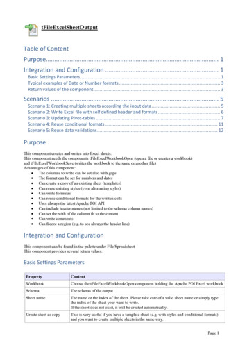
9.5 in.(241 mm)PIC Pressure Instrumentation Column Overall Dimensions20.25 in.(514 mm)3.5 in.(89 mm)45.5 in.(1156 mm)6 in.(152 mm)6 in.(152 mm)Figure 3.1 - PIC Front ViewFigure 3.2 - PIC Side ViewNotes*PIC Shown with Catalytic (Flameless) Heater Mounting Brackets*PIC Shown with Instrumentation Mounting BracketPIC Pressure Instrumentation Column Mounting Configurations6 in.(152 mm)4.625 in.(115 mm)8.25 in.(210 mm)8.25 in.(210 mm)Figure 4.1 - PIC Square Base Mount(Standard)Figure 4.2 - PIC 600 ANSI Weld Neck Flange Mount(Optional)Figure 4.3 - PIC 600 ANSI Lap Joint Flange Mount(Optional)The Square Base Mount is the standard PICmounting arrangement. The PIC is mounted toa solid surface, such as concrete, through fourbolts. The Square Base Mount allows surfacemount of PIC on solid surface (concrete) viafour (4) bolts. This is the standard PIC mounting arrangement. The high pressure connectionfrom pipeline is a 1/2” FNPT port at bottom ofthe PIC. Square Base Mount is available in600 ANSI (standard) and 900 ANSI (optional)pressure ratings. Mounting dimensions for600 ANSI and 900 ANSI Square Base Mountare identical.The Weld Neck Flange incorporates a high capacity3.0 in. (75 mm) Weld Neck Flange connection. TheWeld Neck Flange option provides flange-to-flangeconnection and allows finite rotational position of thePIC in 45 increments. PIC Weld Neck Flange Mountis available in 600 ANSI (standard) and 900 ANSI(optional) pressure ratings. 600 ANSI Weld NeckFlange is shown above.The Lap Joint Flange incorporates a high capacity3.0 in. (75 mm) Lap Joint Flange connection. TheLap Joint Flange option provides flange-to-flangeconnection and allows infinite rotational position.PIC Lap Joint Flange Mount is available in 600 ANSI(standard) and 900 ANSI (optional) pressure ratings.600 ANSI Lap Joint Flange is shown above.3
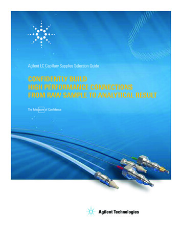
Figure 5 - PIC Port Identification Square Base Mount (standard)*Top view cross sections are shown for each block to facilitate explanation of PIC port configuration.Figure 5.1 - Top BlockLow Pressure(To Heater Fuel)1112Low Pressure(Plug)Low Pressure(Regulated)10Low Pressure8Figure 5.2 - Upper Middle BlockLow Pressure(Plug)Low Pressure(Output)1314Low Pressure(Drain)76Medium Pressure(Input)4Low Pressure(Relief)159Figure 5.3 - Lower Middle BlockMedium Pressure(Plug)Medium Pressure(Output)3Medium Pressure Drain(Plug)Line Pressure(Output)Medium Pressure(Relief)516Figure 5.4 - Bottom BlockLine Pressure(Drain)Line Pressure(Input)21Legend17Supply Regulatorw/ Integral ReliefRelief ValveGageSupplyRegulatorNeedle ValveCustomerConnectionPlugFilter-DryerTable 1 - PIC Pressure Instrumentation Column ComponentsItem123456789DescriptionItem DescriptionPressure Instrument Column (Body) 10 Low Pressure Supply Regulatorw/Integral ReliefHigh Pressure Connection (In)FD-1500 Filter Dryer (Optional)11 Low Pressure Supply GageMedium Pressure Relief Valve12 Heater (1st Stage) Supply RegulatorMedium Pressure Connection (Out)13 Heater (2nd Stage) Supply RegulatorMedium Pressure Supply Regulator14 Heater Fuel Supply ThermocoupleMedium Pressure Supply Gage15 Catalytic (Flameless) HeaterLow Pressure Relief Valve16 Starting Voltage Connection (In)Low Pressure Connection (Out)17 Mounting Flange4Thermo Couple
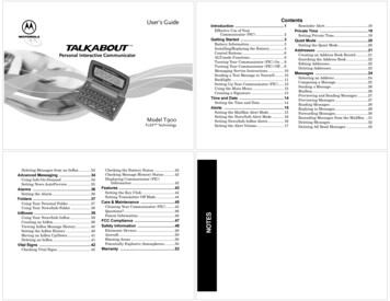
Figure 6 - Typical Installation Schematic for PIC Pressure Instrumentation ColumnThe PIC is shown in a typical installation with a Becker Control Valve and relevant instrumentation components.The PIC provides all necessary pressure levels of instrument supply gas necessary to operate all components.4-20 mA AnalogCommand SignalRPDA RotaryPiston DoubleActing ActuatorHPP-5 HighPressurePositionerT-Ball RotaryControl ValvePIC PressureInstrumentation ColumnP1P2FlowSchematic LegendLow Pressure Power GasLegendPlugSupply RegulatorMedium Pressure Power GasSupply Regulatorw/ Integral ReliefLine PressureGageThermo CoupleCustomer ConnectionNeedle ValveRelief ValveFilter-DryerSignal Pressure5
Figure 7 - Dual PICs Installed in Becker CAB Series Fiberglass EnclosureFigure 8 - Single PIC Installed in Becker CAB Series Fiberglass EnclosureTwo Becker PIC are installed inside a Becker CAB Fiberglass Cabinet. EachPIC provides conditioned and regulated supply gas to a Becker control valve,one PIC for the working control valve and one PIC for the monitor controlvalve. Each PIC also includes the Becker FD-1500 Filter-Dryer to removemoisture from the supply gas. The fiberglass enclosure is required toprevent the catalytic heaters from extinguishing during inclement weather.Each catalytic face heater is hard wired with 120 V A.C. starting voltage andeach disconnect is also located inside the fiberglass enclosure.A Becker PIC is installed inside a Becker CAB Fiberglass Cabinet. The PICprovides conditioned and regulated supply gas to four tube switchingvalves. The outputs to the tube switching valves are located in the upper leftcorner of the cabinet. The PIC includes dual FD-1500 Filter-Dryers completewith independent regulation systems to meet higher capacity requirements.Each FD-1500 and regulator set feeds a pair of the tube switching valves.The PIC system also includes the option of stainless steel components tocomply with no brass application specifications. The catalytic face heater ishard wired with 120 V A.C. starting voltage complete with the disconnectlocated inside the fiberglass enclosure.6
PIC Pressure Instrumentation Column AccessoriesRealize Optimum Performance of your PIC Pressure Instrumentation Column with these popular accessories!Becker Model FD-1500 Filter-DryerThe Becker Model FD-1500 Filter-Dryer filters and dehydrates supply gas for all Becker Control Instrumentation.The FD-1500 Filter-Dryer provides superior filtration and dehydration with 110 inch2 of 10 µ filtering media and2.0 lbs. of silica gel. The FD-1500 incorporates an easy-to-replace "spin on" cartridge made up of a high quality,high capacity nylon and fiberglass filter element reinforced with stainless steel mesh. All FD-1500'sare fully hydrotested to one and a half times the working pressure to ensure the integrity of the pressure vessel.Becker Model FACD-1500 Filter-DeordorizerThe Becker Model FACD-1500 Filter-Deodorizer filters and removes hydrocarbons odor from supply gas for allBecker Control Instrumentation. The FACD-1500 Filter-Deodorizerer provides superior filtration with 110 inch2 of10 µ filtering media and 2.0 lbs. of activated charcoal. The FACD-1500 incorporates an easy-to-replace-spin-oncartridge made up of a high quality, high capacity nylon and fiberglass filter element reinforced with stainless steelmesh. All FACD-1500s are fully hydrotested to one and a half times the working pressure to ensure the integrityof the pressure vessel.Becker Fiberglass Cabinet (CAB)The Becker Fiberglass Cabinet is ideal for the safe enclosure of Becker Below Ground Regulators, PICs, and otherregulating station equipment. The cabinet is particularly useful in areas of extreme weather or fluctuating eIemental conditions. When regulating components must be heated, the cabinet minimizes ambient heat loss. The fliptop cover protects operating personnel during routine maintenance.Becker Thermal Check Valve (TCV)The Becker Thermal Check Valve (TCV) is designed for use with regulated natural gas supply systems. The ThermalCheck Valve offers simple and inexpensive insurance against fire in natural gas regulating stations, compressorstations, or other areas where regulated natural gas supply systems are present. The TCV stops the flow ofcombustible natural gas into potentially hazardous areas in the event of fire or excessive heat.Catalytic (Flameless) HeaterFor PIC applications where freezing may be problematic, the Catalytic (Flameless) Heater is an ideal accessory.The Catalytic (Flameless) Heater provides continuous, flameless heat to PIC and related instrumentation withoutexternal power sources, after heater startup. The catalytic technology operates at a temperatures of 600F - 800 F,ensuring a safe, reliable source of heat. Catalytic (Flameless) Heater startup voltages are available in both 12 V D.C. and 120 V A.C. and are available with both CGA and FM approval ratings. Unit includes all necessaryregulation and components for easy operation.Other Available OptionsThe Becker PIC Pressure Instrumentation Column is available with a variety of options and accessories to suit your applications needs.For more information on these options and accessories, contact Becker. High Pressure Design (900 ANSI) High Volume Capacity Design Multiple Mounting Arrangements- PIC Square Base Mount (standard)- PIC Weld Neck Flange Mount (optional)- PIC Lap Joint Flange Mount (optional) 7Stainless Steel Component ConstructionRadiographic (X-Ray) Testing of Pressure VesselSquare Base Extension Pedestal (Elevate PIC)Custom Instrumentation Mounting BracketsCatalytic (Flameless) Heater ShroudCustom Paint/Coating
SpecificationsItemClassificationMAOPFlow CapacityInlet (Line Pressure) PortAll Other Ports:Weight:Supply Gas RegulatorTypical Pressure RangesHeater SupplyRegulator (Optional)Temperature Range:PIC Series Pressure Instrumentation ColumnSupply Gas System600 ANSI 1480 psig (10,204 kPa)900 ANSI 2175 psig (14,996 kPa)50 SCFM (1.4 std. m3 / min) - Standard PIC Design1/4” FNPT (Standard Square Base Flange Mount)3” Port (Lap Joint Flange Mount)3” Port (Weld Neck Flange Mount)1/4” FNPT20 lbs. (9.0 kg) Standard Square Base, Flange MountPIC - 600 ANSIMedium Pressure Regulator: 100-350 psig (689-2,413 kPa)Low Pressure Regulator: 20-60 psig (138-414 kPa)7.0 in water column-20ºF to 160ºF (-29ºC to 71ºC)Materials of ConstructionPIC BodyIsolation ValvesGaugesFittingsTubing FittingsTubingRelief ValvesMed. Pressure RegulatorLow Pressure RegulatorCatalytic Heater FuelSupply RegulatorAvailable MountingArrangementsHydrostatic TestingCarbon steelPlated steel needle valves (standard)2.5 in. diameter liquid-filled gauges (standard)Plated steel (standard)Dual ferrule 316 SS316 SS seamlessPlated steelPainted Cast Aluminum (standard)Brass (standard)Cast aluminum (standard)600 ANSI Square Base Flange Mount (standard)900 ANSI Square Base Flange Mount (alternate)600 ANSI Weld Neck Flange Mount (alternate)900 ANSI Weld Neck Flange Mount (alternate)600 ANSI Lap Joint Flange Mount (alternate)900 ANSI Lap Joint Flange Mount (alternate)600 ANSI Design - 2220 psig (15,306 kPa) for durationof 4.0 hours900 ANSI Design - 3263 psig (22,494 kPa) for durationof 4.0 hoursCatalytic HeaterHeater TypeFuel TypeFuel Supply PressureHeat OutputAvailable IgnitionVoltagesElectrical ClassificationOptionsSafety ShutoffSelf-sustaining catalytic (no outside power sourcerequired after initial ignition)Natural Gas7.0 in water column6,000 BTU12 V D.C. or 120 V A.C.Figure 9 - PIC Installed Inside Pressure LimitingStation BuildingA Becker PIC is located inside a pressure limitingstation building to provide complete supply gasconditioning to an adjacent Becker monitor controlvalve. This PIC includes the optional Becker FD-1500Filter-Dryer and with the option of a Becker FACD-1500Filter-Deodorizer connected in series to remove anywater vapor and liquid hydrocarbons from the supplygas before entering the regulation stages. The catalyticface heater requires 12 V D.C. or 120 V A.C. startingvoltage. Note the extension cord receptacle located atthe rear of heater. This complete PIC system eliminatescommon problems associated with instrument supplygas such as freezing, liquids, and particulate.FM Approved - Class 1-Division 2-Group D locations byCGA Approved - Class 1-Division 1- Division 2-Group DlocationsAll catalytic heaters are equipped with thermocouplesafety shutoff valvesBecker Precision EquipmentDresser, Inc.1550 Greenleaf AvenueElk Grove Village, Illinois 60007 USAPh: 847.437.5940Toll Free Phone: 800.323.8844Fax: 847.437.2549Email: becker@dresser.com 2008 Dresser, Inc.Becker and Dresser are registered trademarks of Dresser, Inc.www.dresser.comPIC6.09
Two Becker PIC are installed inside a Becker CAB Fiberglass Cabinet. Each PIC provides conditioned and regulated supply gas to a Becker control valve, one PIC for the working control valve and one PIC for the monitor control valve. Each PIC also includes the Becker FD-1500 Filter-Dryer to remove moisture from the supply gas.