Transcription
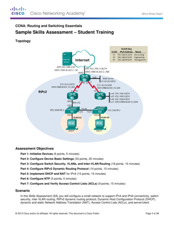
ArresterFacts 010The Lightning Surge and ArrestersArresterFacts 010The Switching Surgeand ArrestersPrepared byJonathan WoodworthConsulting EngineerArresterWorksSeptember 12, 2008Copyright ArresterWorks 2008Jonathan J. WoodworthPage1
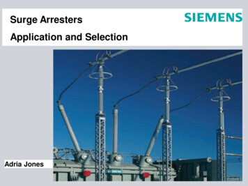
ArresterFacts 010The Switching Surge and ArrestersThe Switching Surge and Arresters4) They always involve trapped energyand its release.Unlike the lightning surge, the switching surgeis generally self induced by the operation of abreaker, switch or disconnect switch.However switching surges can be associatedwith lightning if during a lightning storm alightning surge causes a breaker to operateand a switching surge is induced.ContentsIntroductionThe Switching Surge DefinedSources of Switching SurgesTraveling WavesLocations of Switching SurgesLine Energization Energy RequirementsShunt Bank Re-strike Energy RequirementsIntroductionThis ArresterFacts is about the switchingsurge from an arrester perspective. This textdoes not try to add any new data to the vastknowledge database on switching, but is anoverview of the effect switching surges haveon the power systems and how arrestersmitigate that effect.As with lightning surges, the reasonswitching surges are a concern is that theycan produce voltage levels that can damageinsulation or cause flashover of insulation.Damage and flashovers often lead to outageminutes on a power system and this ishighly undesirable in today’s industry.Figure 1 is an example of a typical switchingsurge. The wave shape is very complex.The amplitude of this switching surge is about2.5pu which is a quite common amplitude forswitching surges. Also note the duration of3pu2pu1pu0There are only a few things one needs toknow about the switching surge to effectivelymitigate them with an arrester, and that isthe focus of this document.The Switching Surge DefinedFigure 2: Typical Switching Surge Effect on Power Systems1pu2puFigure 1 Typical Switching Surge Effect on a Power SystemThe switching surge comes in many differentthis event is not much more than one powerforms, and has many different sources. Whatfrequency cycle which again is quite commonis consistent between all switching surgein switching surge events.events are:1) They are low frequency events usuallySources of Switching Surgesunder a kilohertz and related to theThe reason switching surges exist is becausefundamental power frequency.of the inherent inductance and capacitance of2) They are always associated with apower systems. The lines and transformerschange in the operating state of theare major contributors of inductance. Thesystem.lines are also very capacitive relative to earth3) They are always associated with aand other phases. Cables in undergroundswitching event on the power system.Copyright ArresterWorks 2008 Jonathan J. WoodworthPage22pu
ArresterFacts 010The Switching Surge and Arresters2pusystems offer significant capacitance tosystems. Capacitor banks and reactors alsoadd reactance to the circuits. Wheneverthese inductive and capacitive componentsare added or removed, they require thesystem to find a new steady state voltagelevel and current flow. In the process ofmaking the transition from one systemconfiguration to the next, voltages rise and fallrapidly seeking a new balance. The currentsflow accordingly and often cause currentsurges simultaneously with the voltage surge.In the circuit shown in Figure 2 several typesof switching surges can be created when S1,Figure 2: Typical Double Shunt Banks on a TransmissionLineS2 or S3 are operated.If S1 is closed to energize the line, a 1pusurge travels down the line toward thetransformer and is reflected back toward S1.This reflection can cause a 2pu switchingsurge that will appear on the system and putall insulation in a higher stress situation.Another scenario is if upon closing or openingS2 and S3 either pre-strikes or restrikes of theswitch can lead to switching surges 2pu to3pu as shown in Figure 3.Copyright ArresterWorks 20081pu01pu2puFigure 3: Typical Transient due to closing a switch toenergize a lineTraveling WavesFor as long as there have been transmissionlines, there has been the phenomenon oftraveling waves. All transients on powersystems are influenced by the fact that theireffect is transferred throughout the systemone meter or one unit at a time. This transferof charge and energy is known as a travelingwave. The speed of the wave approachesthe speed of light on transmission lines butdue to the higher capacitance of undergroundcable it is only about half the speed of light.It is this traveling wave characteristic oftransients that lead to reflections andrefractions on the system. These reflectionsof the wave at points on the system where thesystem characteristics change are the mostsignificant reason for transients above 1pu.When there is a termination of a line, theeffect of traveling waves is most pronounced.In this case, the wave is fully reflected and thetransient effect at the source can be a full2pu.Because switching surges are generally lowin magnitude when compared to lightning andslow in frequency as compared to lightning,they act quite differently on the system. Dueto the traveling wave phenomena, the samesource of a surge can affect the system forhundreds and hundreds of miles in eachdirection. In the US, if a circuit breaker isJonathan J. WoodworthPage3
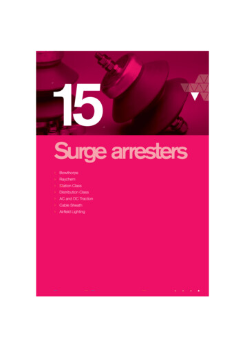
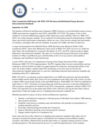
ArresterFacts 010The Switching Surge and Arrestersoperated on a line in California, its affect canbe felt in Montana 500 miles away.too short and the impedances too low for anysignificant switching surge activity.Geographic Locations of theSwitching SurgeLine Energization and ArresterEnergy RequirementsFigure 4 shows where switching surges arefound in the US. Wherever there is atransmission line, there is a possibility ofhaving switching surges. Sometimes thesurges are irrelevant on lower voltage lines( 230kV) but they will be there. Switchingsurges can occur on distribution systemswhere capacitance and URD cable areprominent. Overhead distribution lines areSince arresters are voltage limiting devices,any time a switching voltage exceeds its turnon level, the arrester will conduct andsuppress the surge. Arresters are generallychosen to provide the most protectionpossible for equipment thus their turn onvoltage is normally 1.6 to 1.9 pu of the line toground voltage so any switching surge above2pu will have an effecton the arrester. Whenthe arrester is inconduction, it isdissipating energy andheating. If the switchingsurge is high enough inmagnitude and longenough in duration, itcan stress the arresterbeyond its limits.Fortunately this theenergy related toswitching surges iseasily calculated and thearresters chosen for thistype of protection can beappropriately sized.Figure 5 shows energyvs switching surge level for different systemvoltages using an arrester with a standardturn-on voltage In section 5.3 of IEEEstandard C62.22 and in section 3.2.3.3 of IECstandard 60099-5 the algorithms are given forcalculating the energy a system would imparton an arrester in a line energization event of aswitching surge of different magnitudes.Figure 4: Locations of Switching Surges in US(The map is available at www.researchandmarkets.com)Copyright ArresterWorks 2008Jonathan J. WoodworthPage4
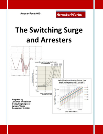
ArresterFacts 010The Switching Surge and ArrestersShunt Bank Re-strikesand Arrester EnergyRequirements.As stated earlier, if a cap bankexperiences a prestrike or restrike,stored energy in the caps canresult in a switching surge. It isestimated that from this type ofswitching surge, a 3pu surge is themaximum possible amplitude.Figure 6 is derived using equationsgiven in 60099-5 section 3.2.3.3.Also for the curve derivation theminimum MCOV arrester for eachsystem is used.Figure 5 Energy Injected into the arrester from a switching surge (100mile line, minimum MCOV)The fundamental purpose ofarresters on transmission systemsare to mitigate the effects ofswitching surges. They will alsomitigate the effects of lightning and ifdimensioned properly for one, they willmitigate properly for the other.Other ArresterFacts AvailableArrester Lead LengthField Testing ArrestersInfrared ThermometerGuide for Selecting an Arrester FieldTest MethodVI CharacteristicsThe Externally Gapped Arrester (EGLA)The DisconnectorUnderstanding Mechanical Tests ofArrestersWhat is a Lightning Arrester?The Lightning SurgeArresterFacts UsageArrester Facts are Copy right ed documents intend edfor the education of arrester us ers andstakehold ers. If you choose to copy any part of thisdocument for t eachin g purposes you hav e mypermission, ho wev er please give Arrest erWorksproper credit.Thank you for usin g www.ArresterWorks.com asyour source of information on high voltage surgearresters.Figure 6 Shunt Bank Energy Discharge LevelsCopyright ArresterWorks 2008Jonathan J. WoodworthPage5
suppress the surge. Arresters are generally chosen to provide the most protection possible for equipment thus their turn on voltage is normally 1.6 to 1.9 pu of the line to ground voltage so any switching surge above 2pu will have an effect on the arrester. When the arrester is in conduction, it is dissipating energy and heating. If the switching surge is high enough in magnitude and long .File Size: 533KBPage Count: 5