Transcription
U SER INS T RU C TION SFlowserve Valtek Control Products f Mark One and Mark Two Control Valves fExperience In Motion
ValtekMarkOneand Mark TwoValtek Mark One and Mark Two ControlValvesFCDVLENIM001-03AQ Control- 12/17 ValvesContents1 General Information2 Unpacking3 Installation4 Quick Check5 Valve Maintenance6 Disassembly and Inspection7 Assembly and Installation8 Severe Service Trim Options8.1 CavControl8.2 ChannelStream8.3 Diamondback8.4 MegaStream8.5 Stealth8.6 TigerTooth8.7 Sidewinder34556791212121314141414FiguresFigure 1 – Mark One Control Valve Body Assembly(optional angle body)Figure 2 – Pressure Balanced Mark One ControlValve Body AssemblyFigure 3 – Exploded View Mark One Body AssemblyFigure 4 – Soft Seat AssemblyFigure 5 – Actuator Stem / Stem Clamp AlignmentFigure 6 – Mark One with CavControl Trim Body AssemblyFigure 7 – Mark One with ChannelStream Trim Body AssemblyFigure 8 – Diamondback Trim Body AssemblyFigure 9 – Mark One with MegaStream Trim Body AssemblyFigure 10 – Mark One with Stealth Trim Body AssemblyFigure 11 – Mark One with TigerTooth Trim Body AssemblyFigure 12 – Sidewinder Trim Assembly468101012121213131314TablesTable I – Common LubricantsTable II – Suggested Bonnet Bolting Torque ValuesTable III – Troubleshooting Chart79152VLENIM0001-04-A4-3/192
Valtek Mark One and Mark Two Control Valves FCD VLENIM001-03 AQ - 12/171 General Information1.3.21.1 UsingThe following instructions are designed to assist in unpacking,installing and performing maintenance as required on Flowserveproducts. Product users and maintenance personnel should thoroughlyreview this bulletin prior to unpacking, installing, operating, orperforming any maintenance. In most cases, Flowserve valves,actuators and accessories are designed for specific applications (e.g.with regard to medium, pressure, and temperature). For this reason,they should not be used in other applications without first contactingthe manufacturer. The product Installation, Operation, and MaintenanceInstructions provides important additional safety information.1.2 ApplicabilityThe following instructions are applicable to the maintenance andinstallation of Flowserve Valtek Mark One and Mark Two globe andangle body design control valves. These instructions cannot claim tocover all details of all possible product variations, nor can they provideinformation for every possible example of installation, operation ormaintenance. This means that the instructions normally include onlythe directions to be followed by qualified personal using the product forits defined purpose. If there are any uncertainties in this respect,particularly in the event of missing product-related information,clarification must be obtained via the appropriate Flowserve sales office.All Flowserve User Manuals are available at www.flowserve.com.1.3 Terms Concerning Safety1.3.1cThe safety terms DANGER, WARNING, CAUTION and NOTEare used in these instructions to highlight particular dangersand/or to provide additional information on aspects that maynot be readily apparent.DANGER: Indicates that death, severe personal injury and/orsubstantial property damage will occur if proper precautionsare not taken.aWARNING: Indicates that death, severe personal injury and/orsubstantial property damage can occur if proper precautionsare not taken.aCAUTION: Indicates that minor personal injury and/orproperty damage can occur if proper precautions arenot taken.NOTE: Indicates and provides additional technical information,which may not be obvious, even to qualified personnel.Compliance with other notes, which may not be particularlyemphasized, with regard to transport, assembly, operationand maintenance and with regard to technical documentation(e.g. in the operating instructions, product documentation,or on the product itself) is essential, in order to avoid faults,which can directly or indirectly cause severe personal injuryor property damage.1.4 Protective ClothingcDANGER: Flowserve products are often used in problematicapplications (e.g. under extremely high pressures with dangerous,toxic or corrosive mediums). When performing service, inspection,or repair operations, always ensure that the valve and actuator aredepressurized and that the valve has been cleaned and is free fromharmful substances. In such cases, pay particular attention topersonal protection (e.g. protective clothing, gloves, glasses etc.).1.5 Qualified PersonnelQualified personnel are people who, on account of their training,experience and instruction and their knowledge of relevant standards,specifications, accident prevention regulations and operating conditions,have been authorized by those responsible for the safety of the plant toperform the necessary work and who can recognize and avoid possibledangers. Contact your local Flowserve representation for a schedule oftraining schools.1.6 Spare PartsUse only Flowserve original spare parts. Flowserve cannot acceptresponsibility for any damages that occur from using spare parts orfastening materials from other manufactures. If Flowserve products(especially sealing materials) have been on store for long periods of timecheck them for corrosion or deterioration before putting them into use.1.7 Service / RepairTo avoid possible injury to personnel or damage to products, safetyterms must be strictly adhered to. Modifying this product, substitutingnon-factory parts, or using maintenance procedures other than thoseoutlined in these Installation, Operation, and Maintenance Instructionscould drastically affect performance, be hazardous to personnel andequipment, and may void existing warranties. Between the actuator andthe valve there are moving parts. To avoid injury, Flowserve providespinch-point-protection in the form of cover plates, especially whereside-mounted positioners are fitted. If these plates are removed forinspection, service or repair special attention is required. Aftercompleting work the cover plates must be refitted. Apart from theoperating instructions and the obligatory accident prevention directivesvalid in the country of use, all recognized regulations for safety andgood engineering practices must be followed.3VLENIM0001-04-A4-3/19flowserve.com 3
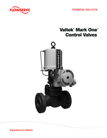
Valtek Mark One and Mark Two Control Valves FCD VLENIM001-03 AQ - 12/17Upper GuidePlug(Item # 87)(Item # 50)Upper Packing(Item # 88)Packing SpacersBody Bolting(Item # 94-99)(Item # 108/114)Lower PackingBonnet Flange(Item # 83)(Item # 70)Lower GuideBonnet(Item # 83)(Item # 40)Bonnet Gasket(Item # 58)Body *(Item # 1)Seat RingSeatRetainer(Item # 20)Seat Gasket(Item # 30)(Item # 55)*Optional angle bodyFigure 1: Mark One Control Valve Body AssemblyaWARNING: Before products are returned to Flowserve for repairor service, Flowserve must be provided with a certificate thatconfirms that the product has been decontaminated and is clean.Flowserve will not accept deliveries if a cleaning certificate has notbeen provided. Return authorization is also required before partsare returned. Contact your local Flowserve representative to obtainreturn authorization.2 Unpacking2.1While unpacking the valve, check the packing list against thematerials received. Lists describing the valve and accessories are included in each shipping container.2.2When lifting the valve from shipping container, use strapsthrough the yoke legs, or the lifting lugs attached to thebody bolting for valves over four inch, or the adjusting screwfor valves four inch and under. Take care to position liftingstraps to avoid damage to the tubing, mounted accessories,or stroke plate.1.8 StorageIn many cases, Flowserve products are manufactured from stainlesssteel. Products not manufactured from stainless steel are provided withan epoxy resin coating. This means that Flowserve products are wellprotected from corrosion. Nevertheless, Flowserve products must bestored adequately in a clean, dry environment. Plastic caps or plywoodprotectors are fitted to help protect the flange faces and prevent theingress of foreign materials. These caps should not be removed untilthe valve is actually mounted into the system.aWARNING: When lifting a valve be aware that the centre ofgravity may be above the lifting point. Therefore, supportmust be given to prevent the valve from rotating. Failure todo so can cause serious injury to personnel and damage tothe valve and nearby equipment.2.3Contact your shipper immediately if there is shipping damage.2.4Should any problem arise, call your Flowserve representative.4VLENIM0001-04-A4-3/194
Valtek Mark One and Mark Two Control Valves FCD VLENIM001-03 AQ - 12/173 InstallationcDANGER: Before installation check the purchase ordernumber, serial number, and/or the tag number to ensurethat the valve and actuator being installed are correct for theintended application.aWARNING: The maximum air supply for most Valtek cylinderactuators is 150 psi (10.3 bar). In some cases, the air supplymust be limited to less than 150 psi (10.3 bar). This isindicated on a sticker found near the upper air port on theactuator cylinder. An air regulator should be installed toensure the supply pressure does not exceed the actuatordesign pressure indicated on the sticker.aCAUTION: Do not insulate extensions that are provided forhot or cold services.aCAUTION: On valves equipped with air filters, the air filtermust point down to perform properly.NOTE: Selecting the proper fastener material is theresponsibility of the customer. Typically, the supplier doesnot know what the valve service conditions or environmentmay be. Flowserve‘s standard body bolting material is B7/2H.B8/8 (stainless steel) is optional for applications more than800 F / 425 C and with stainless steel or alloy body valves.The customer therefore must consider the material‘s resistanceto stress corrosion cracking in addition to general corrosion.As with any mechanical equipment, periodic inspection andmaintenance is required. For more information about fastenermaterials, contact your Flowserve representative.3.1Pipelines must be correctly aligned to ensure that the valve isnot fitted under tension.3.2Fire protection must be provided by the user.3.3Before installing the valve, clean the line of dirt, welding chips,scale and other foreign material.3.4Whenever possible, the valve should be installed in an uprightposition. Vertical installation permits easier valve maintenance.This is also important for cryogenic applications to keep thepacking isolated from the flowing medium, permitting thepacking temperature to remain close to ambient temperature.Contact factory for any valve requiring horizontal mounting.3.5Be sure to provide proper overhead clearance for the actuatorto allow for disassembly of the plug from the valve body. Referto the appropriate actuator User Instructions for properclearances. Actuator User Instructions are available atwww.flowserve.com.3.6Double-check flow direction to be sure the valve is installedcorrectly. Flow direction is indicated by the arrow attached tothe body.VLENIM0001-04-A4-3/193.7If welding the valve into the line, use extreme care to avoidexcess heat buildup in the valve.3.8If the valve has separable end flanges, verify that the halfrings are installed on the valve body before bolting the valveinto the line.a3.9WARNING: Failure to install half rings on the valve body cancause serious personal injury.Connect the air supply and instrument signal lines. Throttlingcontrol valves are equipped with a valve positioner. Refer tothe appropriate positioner bulletin for connections, maximum air supplies, and maintenance instructions. An air filtershould be installed before the positioner. All connectionsmust be free of leaks.aCAUTION: On valves equipped with air filters, the air filtermust point down to perform properly.4 Quick-checkPrior to start-up, check the control valve by following these steps:4.1Stroke the valve and observe the plug position indicator onthe stem clamp compared to the stroke indicator plate. Theplug should change position in a smooth, linear fashion.aWARNING: Keep hands, hair and clothing away from allmoving parts when operating the valve. Failure to do so cancause serious injury.4.2Check for full stroke by making appropriate instrument signalchanges.4.3Check all air connections for leaks.4.4Check packing box bolting for the correct adjustment. Referto the packing installation manual for specific details onmaintaining the style of packing supplied.a4.5CAUTION: Do not overtighten packing. This can cause excessive packing wear, high stem friction that may impede plugmovement and can damage the packing. Over-tightening packing will not improve the stem seal unless the packing has beenpreviously damaged. Damaged packing should be replaced.Make sure the valve fails in the correct direction in case of airfailure. This is done by turning off the air supply andobserving the failure direction.5flowserve.com5
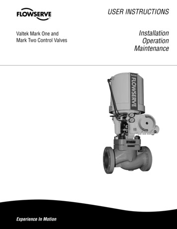
Valtek Mark One and Mark Two Control Valves FCD VLENIM001-03 AQ - 12/17*Optional angle bodyFigure 2: Pressure Balanced Mark One Control Valve Body Assembly5 Valve MaintenanceAt least once every six months, check for proper operation by followingthe preventative maintenance steps outlined below. These steps canbe performed while the valve is in-line and, in some cases, withoutinterrupting service. If an internal problem is suspected, refer to Section6, Valve Disassembly and Inspection.5.15.2Look for signs of gasket leakage through the end flanges andbonnet. Re-torque flange and bonnet bolting (if required).Refer to Table II for bonnet bolt torque values.Examine the valve for damage caused by corrosive fumes orprocess drippings.5.3Clean valve and repaint areas of severe oxidation.5.4Check packing box bolting for proper tightness and packingleakage. If packing leakage is noticed, packing maintenanceis required. Refer to the packing installation manual(document number VLAIM040) for specific details onmaintaining the style of packing supplied.aCAUTION: Do not overtighten packing. This ca
which may not be obvious, even to qualified personnel. 1.3.2 Compliance with other notes, which may not be particularly emphasized, with regard to transport, assembly, operation and maintenance and with regard to technical documentation (e.g. in the operating instructions, product documentation, or on the product itself) is essential, in order to avoid faults, which can directly or indirectly .