Transcription
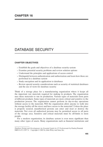
SplinesG Splines can be thought of asa series of axial keywayswith mating keys machinedonto a shaft.G There are two major types ofsplines used in industry: 1)straight-sided splines, and 2)involute splines.G Splines provide a moreuniform circumferentialtransfer of torque to theshaft than a key.Mott, Fig. 11-6
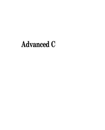
Splined Shaft and HubExternal SplineInternal Splinewww.advanceadapters.com
Spline StandardsG ANSI B92.1-1970 (R1982), Involute Splines,American National Standards Institute.G ANSI B92.2-1980, Metric Module InvoluteSplines, American National Standards Institute.G SAE Straight Tooth Splines
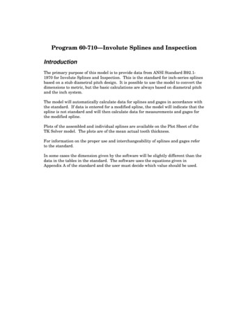
Straight-Tooth SplineGeometryG SAE straight-toothsplines usually contain4,6,10, or 16 splines.G Parameter dimensionsare controlled by the fitneeded for a particularapplication.Mott, Fig. 11-4
Straight-Tooth Spline StrengthG The torque capacity per unitlength of an SAE spline isbased on a 1,000 psi bearingstress on the sides.G Depending on the class of fit, aspline is able to accommodateaxial movement along theshaft and still transmit torque.Splines have the samefailure mechanisms as keys:1) shear or 2) bearing.
Straight-Tooth Spline Strength(Continued)T 1,000 N R h1æD dö D dR ç 2è 2 2ø41h (D d )2D d 1T 1,000 N (D d )4 2T Torque per unit lengthN Number of teethD Major spline diameterd Minor spine diameterd f (D)æ D2 d 2 ö T 1,000 N ççè 8 ø
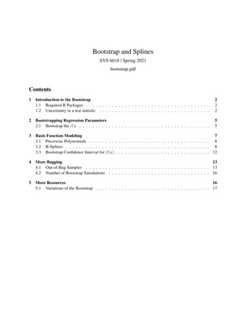
Torque Capacity Curves(SAE Straight-Tooth Splines)Note that an involute spline has a higher torquecapacity than does a straight-tooth spline of the samemajor diameter.Mott, Fig. 11-7
Involute SplinesInvolute splines generallyhave a 30o pressure angle.Mott, Fig. 11-8
Standard Diametral Pitchesand LengthsDiametral PitchesThere are seventeen diametral pitches in common use:2.53456810121620243240486480128Standard LengthsCommon designs use spline lengths of 0.75 D to 1.25 D,where D is the pitch diameter of the spline. When thesestandard lengths are used, the shear strength of the splineswill exceed that of the shaft from which they are made.
Spline Manufacturing MethodsSplines are either “cut” (machined) or rolled. Rolledsplines are stronger than cut splines due to the coldworking of the metal. Nitriding is common to achievevery hard surfaces which reduce wear.Rolled Spline ProcessForged blank is rolled under tonsof pressure prior to heat treating.The finished spline is more accurateand stronger (35%) than cut spines.www.drivetraindirect.com
Spline Failure ExampleNote the yielding of the shaft outside of the engagement areadue to a torsional load. The mating internal spline forced theexternal slines to remain parallel. In this case the spline isstronger than the shaft.www.4wdonline.com
Splined Linear BearingCircular shaped splineshave been combined withball bearings to create linearbearings that can resist atorsional load.www.tsubaki.com
PolygonsAn alternative to splines that has significantlylower stress concentration is the polygon. Fourand three lobed polygons are shown.Design information on polygons isavailable from General Polygon.www.generalpolygon.com
Retaining RingsG Retaining rings are used on shafts tomaintain the axial position ofcomponents.G There are many types of retaining rings.In general, they may be classified as: 1)Externalinternal and 2) external.Internalwww.rotorclip.com
Different Types of RetainingRingswww.mdmetric.com
Spring Loaded Retaining RingsG“Bowed” retaining rings provide restoringforces to the components being held.GFlat retaining rings allow small amounts ofaxial motion of the held component.Bowed InternalRetaining RingBowed ExternalRetaining Ringwww.rotorclip.com
Smalley Compression SpringRetaining SystemHigher restoring forces can be obtainedusing compression rings manufactured bySmalley.www.smalley.com
Retaining Ring StressConcentrationsG External retaining rings usedon shafts require that groovesbe cut into the shaft.G The grooves generally havesharp corners or very smallfillet radii which result insignificant stress concentrationfactors.Mott, Fig. 11-5
Retaining Ring StressConcentration FactorsG The high stresses at the root ofthe retaining ring groove will behighly localized and will notsignificantly effect the staticstrength of a shaft made from aductile material.G The stress concentration factorswill be important in determiningthe life of the shaft and must beincluded in life calculations.Shigley, Fig. A15-14 & 15
Retaining Ring DesignDimensions and design guidelines for retaining ringsare contained in catalogs and literature published byretaining ring manufacturers.Rotoclip, Inc.SmalleyWaldes Truarc, Inc.Designs that use retaining rings must take into accounthow the rings will be installed and make sure thatsufficient assembly clearance is provided.
Integral ShaftsG An alternative to attachingcomponents to shafts is tomachine the componentsdirectly onto the shaft.G This higher priced approach isoften the only approachavailable when tight spaceconstraints exist.G Complex combinations ofcomponents can be obtainedusing modern CNC turningcenters.www.astas.co.za/shafts.html
Assignment1) Make a drawing of an SAE straight-tooth- 4-splineconnection having a major diameter of 1.5000 inand a class A fit. Show all critical dimensions.What is the torque capacity of the spline?2) Identify two applications of retaining rings usedin mechanical equipment. Describe theapplications and discuss why you think retainingrings of the type used were chosen by thedesigner.
ANSI B92.1-1970 (R1982), Involute Splines, American National Standards Institute. ANSI B92.2-1980, Metric Module Involute Splines, American National Standards Institute. SAE Straight Tooth SplinesFile Size: 427KBPage Count: 22People also search fortypes of tripod photographygenetic engineering moviessplines geometrytypes of digital evidence definitiontypes of rhyme oppositesplines