Transcription
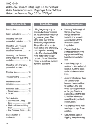
Bulletin 71.1D103087X012Type HSRDecember 2017Type HSR Pressure Reducing Regulator forResidential, Commercial or Industrial Applications High Capacity Compact Design High CapacityInternal ReliefP1524 1Type HSR Angle Body Globe Bodies Angle Bodies Fixed Factor /PFM AccuracyP1275 1 Meets or ExceedsANSI B109.4 / CSA 6.18 RequirementsType HSR GLOBE BODY
Type HSRSpecificationsThe Specifications section lists specifications for Type HSR Pressure Reducing Regulators. Specifications for a given regulator as itoriginally comes from the factory are stamped on the spring case nameplate.Body Sizes (Inlet x Outlet) and End Connection StylesGlobe Body: 3/4, 3/4 x 1, 1 and 1-1/4 NPTAngle Body: 3/4, 3/4 x 1 and 1 NPTAllowable Inlet Pressures(1)Emergency: 150 psig / 10.3 barMaximum Operating Pressure: See Table 1Allowable Outlet Pressures(1)Emergency (Casing): 25 psig / 1.7 barMaximum Operating Pressure to Avoid InternalParts Damage: 3 psi / 0.21 bar differential above outletpressure settingOutlet Pressure RangesSee Table 2Orifice SizesSee Table 1Typical Regulating Capacities3/4 NPT Globe: See Table 83/4 x 1 NPT Globe: See Table 91 NPT Globe: See Table 101-1/4 NPT Globe: See Table 113/4 NPT Angle: See Table 123/4 x 1 NPT Angle: See Table 131 NPT Angle: See Table 141% Pressure Factor Accuracy: See Tables 6 and 7Flow and Sizing CoefficientsSee Table 4Internal Relief PerformanceApproximate Internal Relief Start-To-Discharge Point:6 to 12 in. w.c. / 15 to 30 mbar above outlet pressure setting(Applies to 6 to 8 in. w.c. / 15 to 20 mbar and 8 to 10 in. w.c. /20 to 25 mbar springs only)Relief Performance: See Figures 3 and 4 and Table 14Temperature Capabilities-20 to 160 F / -29 to 71 CPressure Setting AdjustmentAdjusting ScrewPressure RegistrationInternalLockup Performance During Normal OperationORIFICE SIZELOCKUP ABOVESETPOINTLOCKUP ABOVESETPOINTIn.mmIn. ing Case Vent ConnectionStandard: 1 NPT with removable screenOptional: 3/4 NPT with removable screenConstruction MaterialsBody: Cast ironBody Gasket: Nitrile (NBR)Closing Cap: ASA thermoplastic (provides UV-ray protection)Adjusting Screw: Delrin Diaphragm Case, Spring Case, Diaphragm Plate, Orificeand Valve Stem: AluminumPusher Post or Relief Valve Seat: Delrin Diaphragm and Disk: Nitrile (NBR)Control Spring: Zinc-plated steelRelief Valve Spring: Stainless steelRelief Valve Spring Retainer: Stainless steelVent Screen: Stainless steelLever Pin: Stainless steelSpring Seat, Lever and Other Metal Parts: Plated steelBody Vent Mounting PositionsSee Figure 5Approximate Weight4 lbs / 2 kgDesigned, Tested and Evaluated Consistent With:ANSI B109.4 / CSA 6.181. The pressure/temperature limits in this Bulletin and any applicable standard or code limitation should not be exceeded.IntroductionThe Type HSR direct-operated, spring-loaded regulators provideeconomical pressure reducing control in a variety of residential,commercial and industrial applications. These regulators can beused with natural, manufactured or liquefied petroleum gases andhave the same inlet and outlet pressure capabilities.Delrin is a mark owned by E.I. du Pont de Nemours and Co.2In addition, the Type HSR regulators have internal relief acrossthe diaphragm to help minimize overpressure. Any outlet pressureabove the start-to-discharge point of the nonadjustable reliefvalve spring moves the diaphragm off the relief valve seat,allowing excess pressure to bleed out through the screenedspring case vent.
Type HSRControl (main) springStemRelief valve springValve diskPusher postOrificeE0908 08/2007LeverInlet PressureOutlet PressureAtmospheric PressureFigure 2. Type HSR Pressure Regulator Operational SchematicTable 1. Maximum Operating Inlet PressureORIFICE SIZEIn.mmWIDE-OPEN CgFOR RELIEF 5185MAXIMUM OPERATING INLET PRESSURE TO OBTAIN GOOD REGULATING PERFORMANCEpsigbar1251006030208.66.94.12.11.2Table 2. Outlet Pressure RangesOutlet pressure rangeSpringcolorStandardClosingCap ColorBlackIn. w.c.mbarSpring partnumber4 to 610 to 15T14398T0012OrangeSPRING WIRE DIAMETERSPRING FREE LENGTHIn.mmIn.mm0.0621.573.4086.46 to 815 to 20T14399T0012YellowBlack0.0671.703.6191.48 to 1020 to 25T14405T0012BlackBlack0.0671.703.7194.010 to 12.525 to 31T14400T0012SilverBlack0.0721.834.1010412.5 to 2031 to 50T14401T0012GrayBlack0.0802.033.6091.420 to 3550 to 87T14402T0012PinkBlack0.0932.363.5288.91.25 to 2.2 psig0.09 to 0.15 barT14403T0012Light BlueRed0.1052.673.6694.0Table 3. Standard Outlet Pressures and Set FlowsOutlet pressure rangeIn. w.c.Standard outlet set pressurembarIn. w.c.STANDARD SET GAS FLOW, Scfh / Nm3/hmbar4 to 610 to 155126 to 815 to 207178 to 1020 to 2592210 to 12.525 to 31112712.5 to 2031 to 50143520 to 3550 to 871 psi0.07 bar1.25 to 2.2 psig0.09 to 0.15 bar2 psi0.14 bar50 / 1.3Table 4. Flow and Sizing CoefficientsOrifice sizeIn.1/83/161/43/81/2mm3.24.86.49.513Wide-open resizing relief iec sizing coefficientsxt0.78fd0.820.820.820.790.79Fl0.893
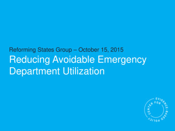
Type HSRTable 5. Standard Inlet Pressures for Set FlowsIn.1/83/161/43/81/2Orifice sizeINLET PRESSURE FOR SET 513For each orifice size, the outlet pressure setting is made with the same inlet pressure regardless of outlet pressure. Example: 3/16 in. / 4.8 mm orifice uses 50 psi / 3.5 bar inlet for 5 in. w.c.through 2 psi / 12 mbar through 0.14 bar outlet settings.Principle of OperationCapacity InformationRefer to Figure 2. When downstream demand decreases, the pressureunder the diaphragm increases. This pressure overcomes the regulatorsetting (which is set by a spring). Through the action of the pusher postassembly, lever and stem the valve disk moves closer to the orifice andreduces gas flow. If demand downstream increases, pressure under thediaphragm decreases. Spring force pushes the pusher post assemblydownward and the valve disk moves away from the orifice. Type HSRregulators include an internal relief valve for overpressure protection. Ifthe downstream pressure exceeds the regulator setting by 7 in. w.c. to1.25 psig / 17 mbar to 0.09 bar, depending on the main spring used, therelief valve opens and excess gas escapes through the vent in the upperspring case.The high efficiency flow-through design provides maximum capacityfor a given orifice size. Tables 6 through 14 give the HSR Seriesflow capacities at selected inlet pressures and outlet pressuresettings. Flows are in scfh (at 60 F and 14.7 psia) and Nm3/h(at 0 C and 1.01325 bar) of 0.6 specific gravity natural gas. Todetermine equivalent capacities for air, propane, butane or nitrogen,multiply the listed scfh capacity by the following appropriateconversion factor: air–0.775 for air, propane–0.628, butane–0.548,nitrogen–0.789. For gases of other specific gravities, multiply thegiven SCFH capacity by 0.775 and divide by the square root of theappropriate specific gravity. If capacity is desired in Nm3/h, multiplySCFH by 0.0268.InstallationFor Critical Pressure DropsThe HSR Series regulators may be installed in any position.However, the spring case vent should be pointed downward. Ifgas escaping through the Type HSR internal relief valve couldconstitute a hazard, the spring case vent must be piped to alocation where escaping gas will not be hazardous. If the ventedgas will be piped to another location, obstruction-free tubing orpiping at least equal to the vent and the end of the vent pipe mustbe protected from anything that might clog it. Dimensions areshown in Figure 6.Use this equation for critical pressure drops (absolute outlet pressureequal to one-half or less than one-half the absolute inlet pressure).Type HSR Flow Capacity for PressureFactor MeasurementFor Non-Critical Pressure DropsTables 6 and 7 contain the flow capacities for the Type HSR ataccuracies of /- 1% of absolute pressure. This data can be usedin applying the regulator in Pressure Factor Measurement (alsocalled Fixed Factor Measurement) or other applications requiringbetter accuracy. Normally pilot operated regulators with highaccuracy are required for these applications. However, as shown inthe table, by flow testing and by limiting the droop on flow capacity, /- 1% of absolute pressure is obtained.Overpressure ProtectionThe wide-open Cg for relief sizing (see Table 1) along with thecapacity information should be used in choosing appropriateoverpressure protection devices to ensure that none of the limits inthe Specifications section are exceeded.Overpressuring any portion of a regulator or associated equipmentmay cause leakage, parts damage or personal injury due tobursting of pressure-containing parts or explosion of accumulatedgas. Regulator operation within ratings does not prevent thepossibility of damage from external sources or from debris in thepipeline. A regulator should be inspected for damage after anyoverpressure condition.4Q P1(abs)Cg(1.29)where,QCgP1 gas flow rate, scfh gas sizing coefficient absolute inlet pressure, psiaFor pressure drops lower than critical (absolute outlet pressure greaterthan one-half of absolute inlet pressure), use the following formula:Q 520GTCgP1SIN3417C1PP1DEGwhere,QGTCgP1C1P gas flow rate, scfhspecific gravity of the gasabsolute temperature of gas at inlet, Rankinegas sizing coefficientabsolute inlet pressure, psiaflow coefficientpressure drop across the regulator, psiThen, if capacity is desired in normal cubic meters per hour at 0 Cand 1.01325 bar, multiply SCFH by 0.0268.Ordering InformationCarefully review each specification and complete the Ordering Guideon page 23. Send the Ordering Guide to your local Sales Office.
Type HSRTable 6. Typical HSR Regulating Capacities for a 3/4 NPT Outlet Body Size with 1% Pressure Factor AccuracyOutlet PressureSettingSpring RangeDroop/Boost1 psig /0.07 barSpring T14402T0012Color: Pink /- 1% ABS2 psig /0.14 barSpring T14403T0012Color: Light Blue /- 1% ABSInlet cities in SCFH / nm3/h OF 0.6 Specific Gravity GasOrifice Size, In. / mm1/8 / 3.2(1)200 / 5.4330 / 8.8410 / 11.0510 / 13.7660 / 17.7830 / 22.2970 / 26.01130 / 30.31440 / 38.61760 / 47.22150 / 57.6250 / 6.7380 / 10.2480 / 12.9650 / 17.4800 / 21.4920 / 24.71100 / 29.51450 / 39.51750 / 46.92000 / 53.63/16 / 4.8(1)220 / 5.9380 / 10.2600 / 16.1810 / 21.71050 / 28.11500 / 40.21850 / 49.62120 / 56.82400 / 64.32600 / 69.72700 / 72.4250 / 6.7450 / 12.1620 / 16.6780 / 20.91150 / 30.81500 / 40.22020 / 54.12250 / 60.32500 / 67.02750 / 73.71/4 / 6.4(1)3/8 / 9.5(2)1/2 / 13(2)220 / 5.9350 / 9.4520 / 13.9890 / 23.91250 / 33.51520 / 40.72020 / 54.12320 / 62.22580 / 69.12850 / 76.4390 / 10.5570 / 15.3830 / 22.21400 / 37.51750 / 46.92050 / 54.92400 / 64.3570 / 15.3770 / 20.61040 / 27.91710 / 45.82150 / 57.62380 / 63.8200 / 5.4350 / 9.4650 / 17.4950 / 25.51210 / 32.41680 / 45.01950 / 52.32300 / 61.62550 / 68.3300 / 8.0510 / 13.71020 / 27.31350 / 36.21680 / 45.02220 / 59.5400 / 10.7750 / 20.11340 / 35.91820 / 48.82120 / 56.8– Gray areas show where indicated droop/boost would be exceeded regardless of capacity.– Blank areas indicate where maximum operating inlet pressure is exceeded for a given orifice.1. Setpoint was established with an inlet of 10 psig / 0.69 bar. The regulators were not reset as inlet pressure was increased or decreased.2. Setpoint was established with an inlet of 5 psig / 0.34 bar. The regulators were not reset as inlet pressure was increased or decreased.Table 7. Typical HSR Regulating Capacities for a 1 NPT Outlet Body Size with 1% Pressure Factor AccuracyOutlet PressureSettingSpring RangeDroop/Boost1 psig /0.07 barSpring T14402T0012Color: Pink /- 1% ABS2 psig /0.14 barSpring T14403T0012Color: Light Blue /- 1% ABSCapacities in SCFH / nm3/h OF 0.6 Specific Gravity GasInlet ice Size, In. / mm1/8 / 3.2(1)200 / 5.4330 / 8.8410 / 11.0510 / 13.7660 / 17.7830 / 22.2970 / 26.01130 / 30.31440 / 38.61760 / 47.22150 / 57.6250 / 6.7380 / 10.2480 / 12.9650 / 17.4800 / 21.4920 / 24.71100 / 29.51450 / 38.91750 / 46.92000 / 53.63/16 / 4.8(1)220 / 5.9380 / 10.2600 / 16.1810 / 21.71050 / 28.11500 / 40.21850 / 49.62120 / 56.82500 / 67.03250 / 87.13950 / 106250 / 6.7450 / 12.1620 / 16.6780 / 20.91150 / 30.81500 / 40.22020 / 54.12250 / 60.32800 / 75.03500 / 93.81/4 / 6.4(1)3/8 / 9.5(2)1/2 / 13(2)220 / 5.9350 / 9.4520 / 13.9890 / 23.91250 / 33.51520 / 40.72020 / 54.12500 / 67.02900 / 77.73400 / 91.1390 / 10.5570 / 15.3830 / 22.21400 / 37.52050 / 54.92600 / 69.73450 / 92.5570 / 15.3770 / 20.61150 / 30.81980 / 53.12550 / 68.33000 / 80.4200 / 5.4350 / 9.4650 / 17.4950 / 25.51210 / 32.41780 / 47.72080 / 55.72550 / 68.33000 / 80.4300 / 8.0510 / 13.71020 / 27.31510 / 40.51900 / 50.92800 / 75.0400 / 10.7750 / 20.11450 / 38.9198 / 53.12350 / 63.0– Gray areas show where indicated droop/boost would be exceeded regardless of capacity.– Blank areas indicate where maximum operating inlet pressure is exceeded for a given orifice.1. Setpoint was established with an inlet of 10 psig / 0.69 bar. The regulators were not reset as inlet pressure was increased or decreased.2. Setpoint was established with an inlet of 5 psig / 0.34 bar. The regulators were not reset as inlet pressure was increased or decreased.5
Type HSRTable 8. 3/4 NPT Globe Body CapacitiesOUTLET PRESSURESETTING, SPRINGRANGE, DROOPAND BOOSt5 in. w.c. /12 mbar4 to 6 in. w.c. /10 to 15 mbar1 in. w.c. droop2 in. w.c. boost7 in. w.c. /17 mbar6 to 8 in. w.c. /15 to 20 mbar1 in. w.c. droop2 in. w.c. boostCAPACITIES IN SCFH / Nm³/h OF 0.6 SPECIFIC GRAVITY NATURAL GAsINLET PRESSUREpsigbarOrifice Size, In. / mm1/8 / 3.23/16 / 4.83/8 / 9.51/2 / 130.50.03--------19
ANSI B109.4 / CSA 6.18 Introduction The Type HSR direct-operated, spring-loaded regulators provide economical pressure reducing control in a variety of residential, commercial and industrial applications. These regulators can be used with natural, manufactured or liquefied petroleum gases and have the same inlet and outlet pressure capabilities.