Transcription
ëTriCore ArchitectureOverview HandbookAbout this DocumentThis document was created with Adobe FrameMaker 5.5.3 at Siemens Microelectronics, Inc.,2480 North First Street, #220, San Jose, California 95131, USA. Revision number and date areshown on each page. This document is not controlled, meaning that no distribution list is maintainedand the reader is responsible for ensuring that he/she is not using an obsolete version.Revision HistoryRelease VersionRelease Date1.006/01/97CommentsBeta release1.109/17/97Preliminary release1.2.001/29/99Instruction set updated, other changes to content.1.2.102/22/99Reformatted for PDF creation, no changes to contentCopyright 1999 Siemens AG.All Rights Reserved.0 2 / 2 2 / 9 9 , v. 1 . 2 . 1
ëAttention please!As far as patents or other rights of third parties are concerned, liability is only assumed for components, not forapplications, processes, and circuits implemented within components or assemblies.This information describes the type of component and shall not be considered as assured characteristics.Terms of delivery and rights to change design reserved.For questions on technology, delivery, and prices, please contact the Semiconductor Group offices in Germanyor the Siemens Companies and Representatives worldwide.Due to technical requirements, components may contain dangerous substances. For information on the types inquestion, please contact your nearest Siemens Semiconductor Group.Siemens, AG is an approved CECC manufacturer.PackingPlease use the recycling operators known to you. We can also help you get in touch with your nearest salesoffice. By agreement, we will take packing material back, if it is sorted. You must bear the cost of transport.For packing material that is returned to us unsorted or which we are not obligated to accept, we shall have theright to invoice you for any costs incurred.Components used in life-support devices or systems must be expressly authorized for such purpose!Critical components1 of the Semiconductor Group of Siemens AG may only be used in life-support devices orsystems2 with the express written approval of the Semiconductor Group of Siemens AG.1. A critical component is a component used in a life-support device whose failure can reasonably be expected tocause the failure of that life-support device or system, and/or to affect the safety or effectiveness of that deviceor system.2. Life-support devices or systems are intended: (a) to be implemented in the human body, or (b) to support and/or maintain human life. If they fail, it is reasonable to assume that the health of the user may be endangered.iiSemiconductor Group02/22/99,v. 1.2.1
ëContents1Chapter 1About this Document .Revision History .iiC ONTENTS .iiivPreface .1INTRODUCING THE TRICORE FAMILY ARCHITECTURE .1.11.21.32TriCore Instruction Categories .Target Applications .TriCore Roadmap .TRICORE PROGRAMMING MODEL .1344Architectural Registers .Data Types and Formats .Memory Model .Addressing Modes .555673TASKS AND CONTEXTS .84INTERRUPT SYSTEM .95TRAP SYSTEM .116PROTECTION SYSTEM .127INSTRUCTION SET HIGHLIGHTS 6Instruction Set Summary .Load and Store Instructions .Arithmetic Instructions .7.3.1Integer Arithmetic .7.3.2DSP and Packed Arithmetic .7.3.3Packed Arithmetic .Comparison Instructions .Bit Operations .Address Arithmetic and Address Comparison .TriCore Architecture Overviewiii02/22/99, v. 1.2.1
ëContents7.77.87.98Branch Instructions .System Instructions .16-bit Instructions .252525TRICORE-1 CORE AND MODULES .26272728298.18.28.38.4TriCore-1 Core .FPI Bus Overview .Peripheral Control Processor Module .Debug/Emulation Module .9TRICORE SOFTWARE DEVELOPMENT TOOLS .3110TRICORE-1 IMPLEMENTATION EXAMPLE .3311DSP EXAMPLE .35GLOBAL PARTNERCHIP FOR SYSTEMS ON SILICON .37TOTAL QUALITY MANAGEMENT .39ivTriCore Architecture Overview02/22/99, v. 1.2.1
ëPrefaceThis document provides an overview of the TriCore Instruction Set Architecture (ISA). This documentis written for engineering managers, hardware engineers, and software engineers.Additional information about the TriCore product line can be found in the following publications.Please call your regional sales office to request these publications. TriCore Architecture Manual TriCore Instruction Set Simulator User’s Guide Introducing TriCore (Brochure) TriCore Development Tools (Brochure)TriCore Architecture Overviewv02/22/99, v. 1.2.1
ëviTriCore Architecture Overview02/22/99, v. 1.2.1
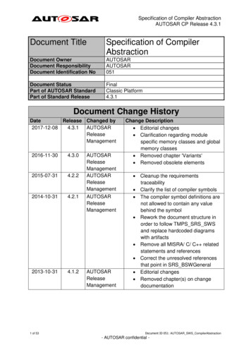
ë1 Introducing the TriCore Family ArchitectureFuture trends for embedded systems include a convergence of microcontroller and DSP architectures, as well as superintegration of memory and logic. Embedded applications are evolving towardsa single system-on-a-chip. This chip of the future will be comprised of a unified microcontroller-DSPcore (32 bits), data and program memory (RAM, ROM, OTP, etc.), and custom application-specificlogic (ASIC), as shown in Figure 1. The single core will provide virtual multiprocessing, which eliminates the need for multiple controllers and DSPs. On-chip memories enhance performance and reduce system power dissipation. The integration of system peripherals and customer-specific logicwill increase overall system performance at a reduced cost. The resident (off-the-shelf) real-time operating system will have a compact kernel with appropriate plug-ins for debug, communications, etc.The application layer on top of the RTOS will be automatically generated with the help of app-builderprograms that draw on rich library routines like DSP, floating-point, and peripheral management.DRAM/SRAMµC DSPROM/OTPFLASHPeripheral / ASICFigure 1: System-on-a-Chip for Embedded ApplicationsThe scenario described above is imperative for the embedded systems of tomorrow. More and moreapplications demand higher system performance at a reasonable cost. System manufacturers are onTriCore Architecture Overview102/22/99, v. 1.2.1
ëIntroducing the TriCore Family Architecturethe classic electronics “treadmill”—faster speeds and increased functionality/features for the same oreven lower price. For example, cellular phones have migrated from analog to digital. Many cellphones incorporate features like paging and voice mail; some even provide internet access and PDA(personal digital assistant) functionality. Form factors have evolved from hand-held to matchbox size.Availability of low power dissipation components allow for increased talk and standby times. And, ofcourse, market prices have dropped dramatically.With cost-effective processor performance, more work can be off-loaded from hardware to softwaretasks running on these powerful multi-tasking CPUs. Combined microcontroller-DSP cores can eliminate the need for dual processors and dual development tool sets. On-chip Flash memory easesfield programmability concerns.The elements for tomorrow’s embedded systems exist today. The TriCore Instruction Set Architecture (ISA) from Siemens Semiconductor combines the real-time capability of a microcontroller, thecomputational power of a DSP, and the high-performance/price features of a RISC load/store architecture onto a compact, reprogrammable core. TriCore is the first single-core 32-bit microcontrollerDSP architecture optimized for real-time embedded systems. You can select peripheral functions(DMA, debug, etc.) from Siemens Semiconductors’ library of peripheral modules. You also canchoose the type and size of on-chip memory: SRAM, DRAM, ROM, Flash, and OTP. The core andperipherals are easily connected to yield a high-performance, cost-effective system-on-a-chip, tailored to your application.Key benefits to using the TriCore for your next real-time embedded system are: The single architecture merges both DSP and microcontroller features without sacrificing the per-formance of either Fast task switching (via an internal wide bus to on-chip memory) allows TriCore to be used effec-tively as a virtual multiprocessor. For example, it can switch from a DSP to a microcontroller taskin two cycles. Large on-chip memory blocks (RAM, ROM, DRAM, OTP, FLASH) result in higher performance,more reliable operation, and reduced system power consumption The architecture allows direct control of on-chip peripherals without additional glue logic. TriCoresupports a lean but powerful memory protection and on-chip debug support scheme. A freely intermixed 16-bit and 32-bit instruction format reduces code size for your application byapproximately 30 to 40%. Interrupts are processed as injected calls and are handled by the same mechanism.The architecture uses a RISC-like register model and load/store architecture to support HLL (HighLevel Language) Compilers and their optimization strategies. Fast context switching and low interrupt latencies enable a flexible distribution of processor performance between concurrent tasks andeffective control of peripheral events. Integrated debug hardware eases the software developmentcycle.The TriCore architecture can save or store half the register context upon an interrupt within two cycles automatically. The architecture thus provides fast interrupt response without having to do a lot ofhousekeeping before entering the real interrupt service routine.2TriCore Architecture Overview02/22/99, v. 1.2.1
ëIntroducing the TriCore Family ArchitectureThe architecture allows for a wide range of implementations, ranging from simple scalar to superscalar. Furthermore, the ISA is capable of interacting with different system architectures, including multiprocessing. This flexibility at the implementation and system levels allows for different trade-offsbetween performance and cost at any point in time.The native microcontroller-DSP capabilities of the architecture allow you to tune through software,the microcontroller and DSP performance of each TriCore core. For instance, the performance of a100-MHz TriCore-1 core with a sustained 130 MIPS rating is 80 microcontroller MIPS 50 DSP MIPS, or 40 microcontroller MIPS 90 DSP MIPS, depending on how the system designer implementsload-sharing in software.The key features of the TriCore instruction set architecture are: 4-GB unified data, program, and I/O space 16- and 32-bit instructions for reduced code size Low interrupt latency Fast context switch using wide pathway to on-chip memory Dual single-clock-cycle 16x16 multiply-accumulate unit Saturating integer arithmetic Extensive bit handling capabilities SIMD packed data operations1.1 TriCore Instruction CategoriesTo optimize code space, the TriCore architecture offers a flexible set of instruction formats. Althoughthe architecture is 32 bits, there are 16-bit instruction formats available to code the most needed instructions in a smaller amount of memory space. This reduces the instruction code space by an average of one third or more, over conventional RISC architectures.The TriCore instructions are subdivided into the following categories. Branch Arithmetic (Integer, DSP, and SIMD Packed Arithmetic) Load/Store Comparison System Bit Manipulation 16-Bit Subset Address Arithmetic and Address ComparisonSee “Instruction Set Highlights” on page 13.3TriCore Architecture Overview02/22/99, v. 1.2.1
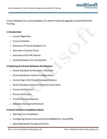
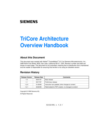
ëIntroducing the TriCore Family Architecture1.2 Target ApplicationsTriCore has been optimized to meet the requirements of embedded applications like computer peripherals, automotive power-train controllers, vehicle dynamics systems, cellular communications,and networking equipment. An increasing number of embedded designs employ both a microcontroller or microprocessor and a DSP or hard-wired ASIC. A TriCore device can replace both these components due to its inherent microcontroller-DSP capabilities and its ability to switch between thosetasks at breakneck speed.1.3 TriCore RoadmapThe TriCore architecture is implemented as a family of cores. A core is a silicon implementation ofthe architecture. Figure 2 shows the future of the TriCore family architecture. The base group ofcores is the TriCore-1 subgroup. TriCore-2 will be a true 64-bit microcontroller with higher degrees ofsuperscalar execution, higher DSP performance, and fast clock speeds. TriCore-3 will perform multithreading, have increased DSP performance over the TriCore-2, and execute at clock speeds in excess of 300 MHz.750TC3TC2 FamilyEnhanced DSP600MIPS450300TC1 FamilyMCU/DSP350 MIPS @ 0.18 500 MIPS @ 0.15 105 MIPS @ 0.25 130 MIPS @ 0.18 150200 MIPS @ 0.15 01999200020012002Figure 2: TriCore Roadmap4TriCore Architecture Overview02/22/99, v. 1.2.1
ëTriCore Programming Model2 TriCore Programming ModelThis section discusses the aspects of the TriCore architecture that are visible to software: the supported data types and formats, the various addressing modes that the architecture provides, and thememory model.2.1 Architectural RegistersThe TriCore architectural registers consist of 32 general-purpose registers (GPRs), two 32-bit registers with program status information (PCXI and PSW), and a program counter (PC). Four GPRs havespecial functions: D15 is used as an implicit data register, A10 is the stack pointer (SP), A11 is the return address register, and A15 is the implicit base address register. PCXI, PSW, and PC are corespecial function registers (CSFRs). The PCXI and PSW registers contain status flags, previous execution information, and protection information.310310310A15 (Implicit Base Addr)A14D15 (Implicit Data)D14PCXIPSWA13A12D13D12PCA11 (Return Address)A10 (Stack Return)D11D10A9 (Global Address reg.)A8 (Global Address reg.)D9D8A7A6D7D6A5A4D5D4A3A2D3D2A1 (Global Address reg.)A0 (Global Address reg.)D1D0AddressDataSystemFigure 3: Architectural Registers (GPRs)2.2 Data Types and FormatsThe TriCore instruction set supports operations on booleans, bit strings, characters, signed fractions,addresses, signed and unsigned integers, and single-precision floating-point numbers. Most instructions work on a specific data type, while others are useful for manipulating several data types. Boolean Bit String Character Address Signed/Unsigned Integer Signed Fraction IEEE-754 single-precisionfloating-point5TriCore Architecture Overview02/22/99, v. 1.2.1
ëTriCore Programming ModelThe general-purpose registers are all 32 bits wide, and most instructions operate on word (32-bit)values. Thus when data with fewer bits than a word is loaded from memory, it must be sign or zeroextended before operations can be applied to the full word. The sign or zero extension is done concurrently as part of the load operation.The data memory and CPU registers store data in little-endian byte order (the least-significant bytesare at lower addresses). Little-endian memory referencing is used consistently for data and instructions. When the TriCore system is connected to an external big-endian device, translation betweenbig- and little-endian format is performed by the bus interface.Alignment requirements differ for addresses and data. Addresses (32 bits) must be aligned on a wordboundary to permit transfers between address registers and memory. For transfers between dataregisters and memory, data may be aligned on any halfword boundary, regardless of size; bytes maybe accessed an any valid byte address, with no alignment restrictions.2.3 Memory ModelThe TriCore architecture can access up to 4 Gbytes of unified program and I/O memory. The addresswidth is 32 bits. The address space is divided into 16 regions or segments (0 through 15). Each segment is 256 Mbytes. The upper four bits of an address select the specific segment. The first 16Kbytes of each segment can be accessed using either absolute addressing or absolute bit addressing with the bit set and bit clear instructions.Figure 4 shows the TriCore architecture’s address space mapping.Segment0Local Static Data1Local Dynamic Data2Local Code3System Bus Memory& Peripherals14External Peripherals15Internal PeripheralsFigure 4: Address Map and Memory Model6TriCore Architecture Overview02/22/99, v. 1.2.1
ëTriCore Programming Model2.4 Addressing ModesAddressing modes allow load and store instructions to efficiently access simple data elements withindata structures such as records, randomly and sequentially accessed arrays, stacks, and circularbuffers. Simple data elements are 8, 16, 32, or 64 bits wide.The TriCore architecture supports seven addressing modes, as listed in Table 1. These addressingmodes support efficient compilation of C, easy access to peripheral registers, and efficient implementation of typical DSP data structures (circular buffers for filters and bit-reversed indexing forFFTs).Table 1: Addressing Modes of the TriCore ArchitectureAddressing ModeAddress Register UseOffset Size(bits)AbsoluteNone18Base Short OffsetAddress Register10Base Long OffsetAddress Register16Pre-incrementAddress Register10Post-incrementAddress Register10CircularAddress Register Pair10Bit-reverseAddress Register Pair—Addressing modes not supported directly in the hardware can be synthesized through short instruction sequences using indexed addressing, PC-relative addressing, or extended absolute addressing.7TriCore Architecture Overview02/22/99, v. 1.2.1
ëTasks and Contexts3 Tasks and ContextsIn this document, the term TASK refers to an independent thread of control. There are two types oftasks: SOFTWARE-MANAGED TASKS (SMTs) and INTERRUPT SERVICE ROUTINES (ISRs). Software-managedtasks are created through the services of a real-time kernel or OS, and are dispatched under the control of scheduling software.Each task is allocated its own permission level, depending on the task’s function. Individual permissions are enabled/disabled primarily through the IO mode bits in the Processor Status Word (PSW).Associated with any task is a set of state elements known collectively as the task’s CONTEXT. The context is everything the processor needs in order to define the state of the associated task and enableits continued execution. It includes the CPU general registers that the task uses, the task’s programcounter (PC), and its Program Status Information (PCXI and PSW). The TriCore architecture efficiently manages and maintains the tasks’ contexts through hardware.The context is subdivided into the UPPER CONTEXT and the LOWER CONTEXT. The upper context consists of the upper address registers, A10 - A15, and the upper data registers, D8 - D15. These registers are designated as non-volatile, for purposes of function calling. The upper context also includesPCXI and PSW. The lower context consists of the lower address registers, A2 through A7, and thelower data registers, D0 through D7, plus the PC. Registers A0 and A1 in the lower address registersand A8 and A9 in the upper address registers are defined as SYSTEM GLOBAL REGISTERS. These registers are not included in either context partition, and are not saved and restored across calls or interrupts. The operating system normally uses them to reduce system overhead.The TriCore architecture uses linked lists of fixed-size CONTEXT SAVE AREAS (CSAs). A CSA is 16words of on-chip memory storage, aligned on a 16-word boundary. Each CSA can hold exactly oneupper or one lower context. CSAs are linked together through a LINK WORD.The TriCore architecture saves and restores context much more quickly than conventional microprocessors and microcontrollers. Its unique memory subsystem design with a wide data path allows theTriCore architecture to perform rapid data transfers between processor registers and on-chip memory.Context switching occurs when an event or instruction causes a break in program execution, resulting in the CPU needing to resolve this event before continuing with the program. These events andinstructions consist of the following:1. interrupt or service requests,2. traps, or3. function calls.8TriCore Architecture Overview02/22/99, v. 1.2.1
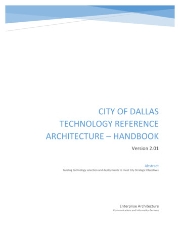
ëInterrupt System4 Interrupt SystemOne key feature of the TriCore architecture is its powerful and flexible interrupt system. The interruptsystem is built around programmable Service Request Nodes (SRNs). A SERVICE REQUEST is definedas an interrupt request or a DMA request. A service request may come from an on-chip peripheral,external hardware, or software.Conventional architectures handle service requests by loading a new Program Status from a vectortable in data memory. With the TriCore architecture, service requests jump to vectors in code memory. This procedure reduces response time for service requests. The first instructions of the interruptservice routine (ISR) execute at least three cycles earlier than they would otherwise.Service requests are prioritized, which enables nested interrupts. A service request can interrupt theservicing of a lower priority interrupt. Interrupt sources with the same priority cannot interrupt eachother. The Interrupt Control Unit (ICU) determines which source will win arbitration based on the priority number.All service requests are assigned priority numbers (SRPNs). Even the CPU has its own priority number. Different service requests must be assigned different priority numbers. The maximum number ofinterrupt sources is 255. Programmable options range from one priority level with 255 sources up to255 priority levels with one source each.Interrupt numbers are assumed to be assigned in linear order of interrupt priority. This is feasible, because interrupt numbers are not hardwired to individual sources. They are assigned by software executed during the power-on boot sequence.Figure 5 shows several examples where Task 1 is interrupted. For a simple interrupt, the TriCore automatically saves the upper context upon entering the Interrupt Service Routine (ISR). Then the upper context registers can be used within the ISR. When the Return from Execution instruction isissued, the upper context from the time of the interrupt is automatically restored.In the general interrupt, the upper context is automatically stored. The ISR explicitly saves the lowercontext using the SVLCX instruction. Both upper and lower context registers can be used within therest of the ISR. Before returning to Task 1, the restore lower context instruction is issued followed bya return from exception, which automatically restores the upper context.In the ISR in the persistent context example, explicit upper and lower context values are loaded frommemory using the LDUCX and LDLCX instructions. These values were saved from a previous call orinterrupt for explicit use in the ISR. At the end of the ISR, new values to be used in a subsequent ISRcall are stored explicitly using the STUCX and STLCX instructions.9TriCore Architecture Overview02/22/99, v. 1.2.1
ëInterrupt SystemInterruptSimple InterruptTask AInterrupt Service RoutineTask ATimeRestoreUpper Context ASaveUpper Context AInterruptGeneral InterruptTask AInterrupt Service RoutineTask ATimeSaveUpper Context ALower Context ARestoreUpper Context ALower Context ALoadUpper Context BLower Context BSimple Interruptwith Context SwitchStoreUpper Context BLower Context BInterruptTask AInterrupt Service RoutineTask ATimeSaveUpper Context ALower Context ARestoreUpper Context ALower Context AFigure 5: Interrupt Examples10TriCore Architecture Overview02/22/99, v. 1.2.1
ëTrap System5 Trap SystemA trap occurs as a result of an event such as a non-maskable interrupt, an instruction exception, orillegal access. The TriCore architecture contains eight trap classes. These traps are further classifiedas synchronous or asynchronous, and hardware or software. Each trap is assigned a Trap Identification Number (TIN) that identifies the cause of the trap within its class.The eight trap classes are: Reset Internal Protection Instruction Errors Context Management Assertion System Bus & Peripheral System Call Non-Maskable InterruptErrors11TriCore Architecture Overview02/22/99, v. 1.2.1
ëProtection System6 Protection SystemThe protection system allows you to assign access permissions to memory regions for data andcode. Protection capabilities are useful for protecting core system functionality from bugs that mayhave slipped through testing. They are also important aids to testing and debugging.The TriCore’s protection system provides the essential features to isolate errors and facilitate debugging. It protects critical system functions against both software and transient hardware errors.The TriCore’s embedded architecture allows each task to be allocated the specific permission level itneeds to perform its function. The three permission levels are: USER-0 MODE is used for tasks that do not access peripheral devices. USER-1 MODE is used for tasks that access common, unprotected peripherals. Interrupts can bedisabled at this level for a short period. SUPERVISOR MODE permits read/write access to system registers and protected peripheral devices.The memory protection model for the TriCore architecture is based on address ranges, where eachaddress range has an associated permission setting. Address ranges and their associated permissions are specified in two to four identical sets of tables residing in Core SFR (CSFR) space. Eachset is referred to as a PROTECTION REGISTER SET (PRS).When the protection system is enabled, the TriCore checks every load/store or instruction fetch address for legality before performing the access. To be legal, the address must fall within one of theranges specified in the currently selected PRS, and permission for that type of access (read, write,execute) must be present in the matching range.12TriCore Architecture Overview02/22/99, v. 1.2.1
ëInstruction Set Highlights7 Instruction Set HighlightsThis section provides high-level details on the TriCore instruction set. Complete information on all instructions can be found in Siemens Semiconductor’s TriCore Architecture Manual.7.1 Instruction Set SummaryThe following table summarizes the TriCore instruction set. Shaded entries indicate 16-bit instructions.13TriCore Architecture Overview02/22/99, v. 1.2.1
ëInstruction Set bsolute valueDVADJDivide adjustABSDIFAbsolute value of differenceDVINITDivide initialization wordABSDIFSAbsolute value of difference with saturationDVSTEPDivide stepABSSAbsolute value with saturationENABLEEnable interruptADDAddEQEqualADDCAdd carryEQANYMultiple compareADDIAdd immediateEQZEqual zero addressADDIHAdd immediate high wordEXTRExtr
between performance and cost at any point in time. The native microcontroller-DSP capabilities of the architecture allow you to tune through software, the microcontroller and DSP performance of each TriCore core. For instance, the performance of a 100-MHz TriCore-1 core with a sustained 130 MIPS rating is 80 microcontroller MIPS 50 DSP MI-