Transcription
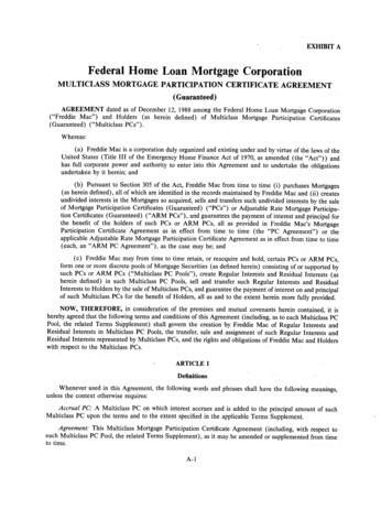
INTRODUCTION TO SERIAL ARMA robot manipulator consists of links connected by joints. The links of the manipulator can be considered to forma kinematic chain. The business end of the kinematic chain of the manipulator is called the end effector and it isanalogous to the human hand. The end effector can be a gripper or can be designed to perform any desired tasksuch as welding, painting, assembly, etc.MECHANICAL DESIGNIn constructing the arm, we made use of five servo motors (including gripper) since our structure allowsmovement in all three dimensions. There is a servo motor at the base, which allows for angular movement of thewhole structure; other two at the shoulder and elbow to allow the upward and downward movement of the arm;one for the movement of the wrist while the last servo motor at the end effector allows for the gripping of objects.The serial arm is a four degree of freedom system. Three DOF control the position of the arm in the Cartesianspace, one for wrist orientation and one additional servo for actuating gripper.The robot features in the control GUI or teach pendant are base rotation, shoulder, elbow, wrist rotate, and afunctional gripper. The base of the robotic arm is made up of Perspex while the links are made up of Aluminium.The serial manipulator uses 1 x HS-485 in the base, 1 x HS-485 in the shoulder, 1 x HS-485 HB in the elbow, 1 xHS-225 in the wrist, and 1 x HS-81 in the gripper.
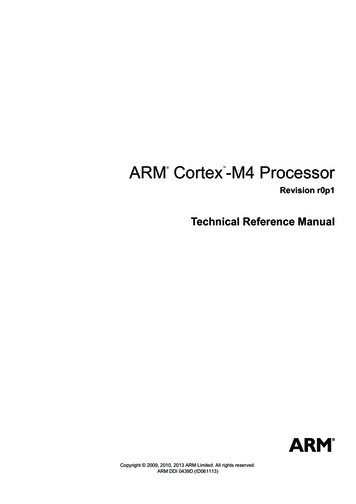
Servo motors serve as the actuators at various joint. These motors feature 180 degree rotation in clockwisedirection. The motors are controlled by Arduino mega microcontroller board upon receiving commands from ahost computer via USB cable.ASSEMBLY DETAILS OF ARMBaseServo Motor(HS485-HB)
MotorHolderDiscServo Motor(HS485-HBLink 1NOTE: Before fixing the links to servomotor’s shaft, the motor shaft be broughtto center position (90 degree) and thenthe links are to be fixed in uprightposition.Servo Motor(HS485-HB)
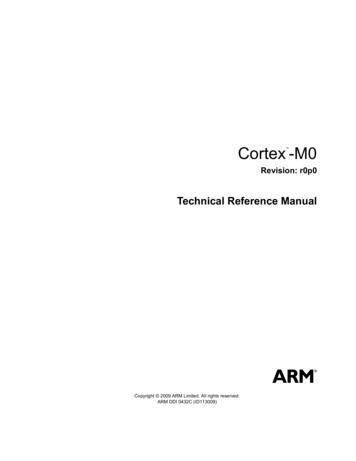
Servo MotorHS225-BBLink-2GripperNOTE: Before fixing the gripper towrist servo, the motor shaft bebrought to center position and thenthe gripper is to be fixed in amanner shown in the figure above.Fully Assembled Serial Arm
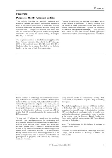
ROBOT WORKSPACEDegrees of Freedom (DOF)A degree of freedom is a joint on the arm, a place where it can bend or rotate or translate. We cantypically identify the number of degrees of freedom by the number of actuators on the robot arm(in case of serial arms). The gripper is often complex with multiple DOF or can be a toll forwelding etc., so for simplicity it is treated as separate subsystem in basic robot arm design.Robot Workspace (Work Volume)The robot workspace (sometimes known as reachable space) is a collection of points that the endeffector (gripper) can reach. The workspace is dependent on the DOF angle/translationlimitations, the arm link lengths, the angle at which something must be picked up at, etc. Theworkspace is highly dependent on the robot configuration. The figure given below describes theworkspace for our serial arm. It should be noted that it does not include the DOF which controlsthe wrist orientation as the workspace is independent of orientation variable.The shoulder and elbow joints rotate a maximum of 180 degrees. To determine the workspace,trace all locations that the end effector (gripper) can reach as in the image below.
Now rotating that by the base joints another 180 degrees to get 3D work volume. This creates aworkspace of a shelled quarter sphere as shown below.
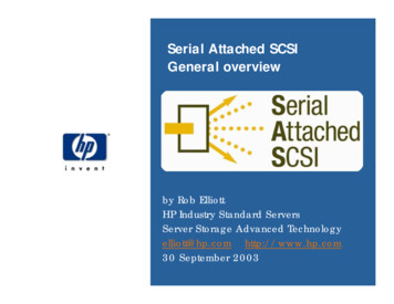
If you change the link lengths you can get very different sizes of workspaces, but this would bethe general shape. Any location outside of this space is a location the arm can’t reach. If there areobjects in the way of the arm, the workspace can get even more complicated.Here are a few more robot workspace examples:Cartesian Gantry Robot ArmCylindrical Robot ArmSpherical Robot Arm
The workspace for our serial arm can be mathematically described in polar coordinates as:, where L1 and L2 represent the lengths of link 1 and link 2respectively and r denotes the polar distanceSimilarly,L1 9.2cmL2 11.5cmINVERSE KINEMATICSForward kinematics is the method for determining the orientation and position of the end effector, giventhe joint angles and link lengths of the robot arm. Inverse kinematics is the opposite of forwardkinematics. It is required when we have a desired end effector position, but need to know thejoint angles in order to achieve it.Suppose we have a planar 2 DOF robotic arm. We are required to find the joint angles in order toplace the end effector at a particular position in Cartesian space. Coordinates of end effectors aretaken as input variables x and y while the base is taken as origin.
, Where d is the polar distance of the end effectors in Cartesian coordinates.Given length of link 1 and link 2 as L1 and L2 we can findSimilarly,&using cosine formula.can also be calculated using the cosine formula.Total angular displacement of motor shaft at joint 1 isTotal angular displacement of motor shaft at joint 2 isELECTRONICS AND CONTROLServo motorServos are a special type of DC motors with built in gearing and feedback control loop circuitryand they don’t require motor controllers. These motors are mainly developed for making robots,toys, etc. that are mainly used for education and not for industrial applications.Servos are becoming extremely popular with robot, RC plane, and RC boat builders. Most servomotors can rotate about 90 to 180 degrees. Some rotate through a full 360 degrees or more.However, servos are unable to continually rotate, meaning they can't be used for driving wheels(unless modified), but their precision positioning makes them ideal for robot arms and legs, rackand pinion steering, and sensor scanners to name a few. Since servos are fully self contained, thevelocity and angle control loops are very easy to implement. To use a servo, we connect theblack wire to ground, the red to a 4.8-6V source, and the yellow/white wire to a signal source(such as from your microcontroller). Vary the square wave pulse width from 1-2ms and the servois now position/velocity controlled.Servo Wiring:All servos have three wires:Black or Brown is for ground.Red is for power ( 4.8-6V).Yellow, Orange, or White is the signal wire (3-5V).Servo Voltage (Red and Black/Brown wires):
Servos can operate under a range of voltages. Typical operation is from 4.8V to 6V. There are afew micro sized servos that can operate at less, and now a few Hitec servos that operate at muchmore.Signal Wire (Yellow/Orange/White wire):While the black and red wires provide power to the motor, the signal wire is what we use tocommand the servo. The general concept is to simply send an ordinary logic square wave to yourservo at a specific wave length (50Hz), and the servo goes to a particular angle. The wavelengthdirectly maps to servo angle. In our case Arduino Mega takes input from the PC and generatesthe corresponding square wave, which in turn controls the angular position of the servo motor.The standard time vs. angle is represented in this chart:BASIC CONCEPT OF ARDUINOOverviewAn Arduino is a single-board microcontroller and a software suite for programming. It isdesigned for an Atmel AVR processor and features on-board I/O support. The software consistsof a standard programming language and the boot loader that runs on the board.We are using Arduino Mega microcontroller board based on the ATmega1280.It has 54 digital input/output pins (of which 14 can be used as PWM outputs), 16 analog inputs,4 UARTs (hardware serial ports), a 16 MHz crystal oscillator, a USB connection, a power jack,an ICSP header, and a reset button.
It contains everything needed to support the microcontroller; simply connect it to a computerwith a USB cable or power it with an AC-to-DC adapter or battery to get started.POWER: The Arduino Mega can be powered via the USB connection or with an externalpower supply. The power source is selected automatically.The power pins are as follows:VIN: The input voltage to the Arduino board when it's using an external power source.5V: The regulated power supply used to power the microcontroller and other components on theboard.3V3: 3.3 volt supply generated by the on-board FTDI chip. Maximum current draw is 50 mA.GND: Ground pins.MEMORY: The ATMEGA 1280 has 128 KB of flash memory for storing code.COMMUNICATION: The Arduino software includes a serial monitor which allows simpletextual data to be sent to and from the Arduino board. The RX and TX LEDs on the board willflash when data is being transmitted via the FTDI chip and USB connection to the computer (butnot for serial communication on pins 0 and 1. It has a number of facilities for communicatingwith a computer, another Arduino, or other microcontrollers.How To Get Arduino Running on WindowsThese are the steps that we'll go through:1. Get an Arduino board and cable
2.3.4.5.6.7.8.Download the Arduino environmentInstall the USB driversConnect the boardRun the Arduino environmentUpload a programLook for the blinking LEDLearn to use Arduino1 Get an Arduino board and cableIn this tutorial, we assume you're using an Arduino Mega.The Arduino is a simple board that contains everything you need to start working withelectronics and microcontroller programming. This diagram illustrates the major components ofan Arduino Mega.You also need a standard USB cable (A plug to B plug): the kind you would connect to a USBprinter, for example.2 Download the Arduino environment
To program the Arduino board you need the Arduino environment.When the download finishes, unzip the downloaded file. Make sure to preserve the folderstructure. Double-click the folder to open it. There should be a few files and sub-folders inside.3 Locate the USB driversIf you are using a USB Arduino, you will need to install the drivers for the FTDI chip on theboard. These can be found in the drivers/FTDI USB Drivers directory of the Arduinodistribution. In the next step ("Connect the board"), you will point Window's Add New Hardwarewizard to these drivers.4 Connect the boardOn Arduino, the power source is selected by the jumper between the USB and power plugs. Topower the board from the USB port (good for controlling low power devices like LEDs), placethe jumper on the two pins closest to the USB plug. To power the board from an external powersupply (6-12V), place the jumper on the two pins closest to the power plug. On the ArduinoMega, the power source is selected automatically (there is no power selection jumper). In anycase, connect the board to a USB port on your computer.The green power LED (labeled PWR) should go on.The Add New Hardware wizard will open. Tell it not to connect to Windows update and clicknext.
Then select "Install from a list or specified location (Advanced)" and click next.
Make sure that "Search for the best driver in these locations is checked"; uncheck "Searchremovable media"; check "Include this location in the search" and browse to the location youunzipped the USB drivers to in the previous step. Click next.
The wizard will search for the driver and then tell you that a "USB Serial Converter" was found.Click finish.The new hardware wizard will appear again. Go through the same steps. This time, a "USBSerial Port" will be found.5 Run the Arduino environmentOpen the Arduino folder and double-click the Arduino application.6 InitializeYou'll need to select the entry in the Tools Board menu that corresponds to your ArduinoMega.
Select the serial device of the Arduino board from the Tools Serial Port menu. On Windows,this should be COM3, COM4, COM5 or a higher COM address for a USB board.
To find out which COM port it is, open the Windows Device Manager (in the Hardware tab ofSystem control panel). Look for a "USB Serial Port" in the Ports section; that's the Arduinoboard.
GETTING STARTEDA) Install Software for ARDUINO MEGA:Download the Arduino IDE from the following link, http://arduino.cc/en/Main/SoftwareComplete installation as per the instructions given in the previous section.B) Install DEV C : Download and install DEV C from the following linkhttp://www.brothersoft.com/dev-c -65296.html.C) Make the Electrical Connections from SERIAL ARM to the ARDUINO MEGA.Ø Connect the red and black wires of all the servo motors to 5V power supply andground respectively.Ø Connect the yellow wires (control signal) of the base, shoulder, elbow, wrist andgripper servo motors to PWM pin 3, 7, 8, 10 and 12 respectively on the ArduinoMega.Ø Connect a common ground wire from the 5V power supply to the “gnd” pin onArduino Mega.D) Connect the ARDUINO MEGA to the System using USB CABLE.E) Copy the CONTROL SOFTWARE to the PC.Ø code.cØ serial.hØ code.exe
An Arduino is a single-board microcontroller and a software suite for programming. It is designed for an Atmel AVR processor and features on-board I/O support. The software consists of a standard programming language and the boot loader that runs on the board. We are using Arduino Mega microcontroller board based on the ATmega1280. .