Transcription
Telecom m unications InfrastructureStandard for Data Centers802.3 TutorialPrepared by: Jonathan Jew - J&M Consultants andChris DiMinico - MC Communications - Co-chairs TR42.1.1
TR42: Data Center StandardPN-3-0092Telecommunications Infrastructure Standardfor Data CentersDraft 2.0July 9, 2003
Telecommunication SP Local LoopInternet DataCenterHomeSOHO-serviceprovidedServiceprovider- DistributionNode-Central OfficeServiceProviderBackbone CustomerleaseServiceproviderLocal Loop- Distribution-serviceNodeprovided-Central OfficeDATA/Voice Infrastructure Data Center EFM- Access NetworksCustomerPremiseISPInternet DataCenterHomeSOHO
Campus Network: California State University Data Center -80’s
Cornell Campus Network, -87
Internet Data CentersnNetwork infrastructure required to drive web hosted Internet applications.
Service Provider Distribution Node- Central Office
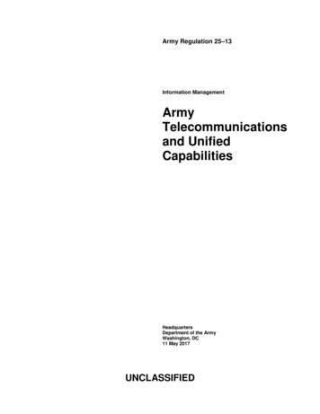
Ethernet Networking -LAN/WAN/SAN10 Gb/sDWDM InfrastructureInternet10 Gb/sRemote EnterpriseWANWAN RouterSwitchEquipment Room10 Gb/sFirewallBackboneSwitch / Router1 mailServers1 Gb/s10 Gb/sApplicationServers10 Gb/s -Internet DataCenter -ComputerRoom
Cabling Topologies and DistancesCable mer PremisesISO/IEC 11801-TIA 100 metersData Center 100 metersCentralOffice 100 metersEquipmentRoomNA 100 meters 100 meters30 meter
Who is Developing the StandardnnThe standard is being developed by the TIA/TR42Engineering Committee - subcommittee-TR-42.1.1Network Distribution Nodes - Project No. 3-0092Participants include:uuuunnArchitecture & Engineering FirmsConsultantsEnd UsersManufacturersThe standard will become TIA-942To be submitted for approval by ANSI and CSA
Status of the Standardnnnnnnn2nd draft released for industry ballot July 2003.Draft posted to IEEE websiteBallot comments to be resolved October 2003.Liaison with other standards organizations (IEEE,CENELEC, BICSI, ISO,ASHRE)Liaison with data center industry organizations(7X24 Exchange,Uptime Institute)Liaison with network and computer equipmentmanufacturersFinal approval expected sometime in 2004
Purpose of the StandardEnabling planning for data centers to occurearlier in the building development process(architectural, facilities, and IT).n Fill a void by providing standards forplanning of data centers, computer rooms,server rooms, and similar spaces.n The standard encompasses much more thanjust telecommunications infrastructure.n Close to half of the technical content dealswith facility specifications.n
Purpose of the standardnnnSpecifications for data center telecommunicationscabling, pathways and spacesRecommendations on media and distance andrestrictions for data center applications overstructured cabling system (TIA 232, TIA 561, T1,E1, T3, E3, 1 & 10 Gigabit Ethernet, FibreChannel)Establish a standard for data center tiers to replaceseveral proprietary standards. The TIA data centertier standard is: A tool to evaluate existing data centers A tool to communicate design requirements
TR42.1 Study Group: Telecommunications CablingInfrastructure for Network Distribution NodesScope: Develop cabling topology, recognized mediatypes, cabling requirements, and requirements forpathways & spaces for data centersnCabling DesignNetwork DesignFacility DesignnInformative annex: Provide best practicesnn
Design Elements:Cabling Design:n Copper and fiber cabling performancen Connectors, cables, distribution hardwaren Cabling distancesn Space managementFacility Design:nData center sizingnPower distribution methodologiesnPathways and spacesnHVAC, security, operations, and administration.nFlexibility, scalability, reliability and space management
Design Elements:Network Design:nSupport legacy systemsnEnable rapid deployment of new technologies suchas the emerging 10 Gb/s applications.
Overview of key elements - NormativeNormative:nClause 5. cabling spaces - definitionsnClause 6. Data center cabling–definitions–topology–recognized media–redundancynClause 7. Data Center Cabling Pathways
Overview of key elements - InformativeInformative:nClause 8: RedundancynAnnex:–application distances–administration–carrier information–site selection–infrastructure tiering–design examples
Distribution Areas - Spaces for cabling elementsCabling elementsnCross-connectnInterconnectDistribution AreasnMain Distribution Area -MDAnHorizontal Distribution Area -HDAnZone Distribution Area - ZDAnEquipment Distribution Area -EDAnEntrance Room
Purpose of the standardnnnnnDefine a standard telecommunicationsinfrastructure for data centersStructured cabling system for data centers usingstandardized architecture and mediaAccommodates a wide range of applications(LAN, WAN, SAN, channels, consoles)Accommodates current and known futureprotocols (10 Gigabit Ethernet)Replaces unstructured point-to-point cabling thatuses different cabling for different applications
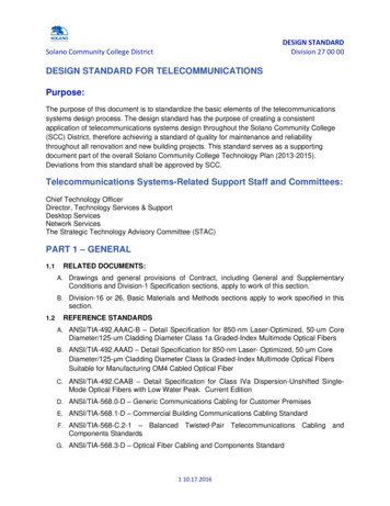
Relationship of SpacesBUILDING SITEBUILDING SHELLGENERAL OFFICESPACETELECOM ROOMS &EQUIPMENT ROOMSfor spaces outside datacenterOFFICE BUILDINGSUPPORT SPACEDATA OOM(S)TELECOM ROOM(S)for data centersupport spacesCOMPUTER ROOMDATA CENTERELECTRICAL &MECHANICAL ROOMSSTORAGE ROOMS& LOADING DOCKS
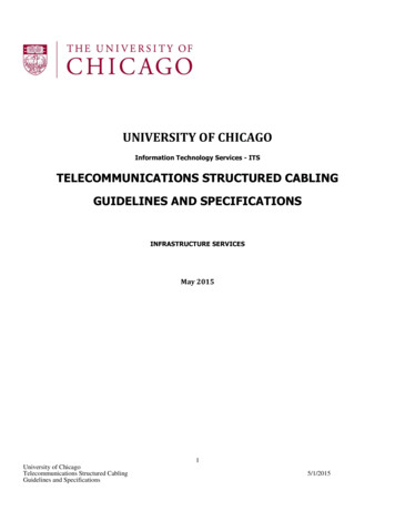
Data Center Telecommunications SpacesCarriersOffices,Operations Center,Support RoomsTelecom Room(Office & OperationsCenter LAN switches)Entrance RoomCarriers(Carrier Equip &Demarcation)Main Dist AreaComputerRoom(Routers, BackboneLAN/SAN Switches,PBX, M13 Muxes)OptionalBackbone CablingHoriz Dist Area(LAN/SAN/KVMSwitches )Zone Dist AreaHoriz Dist Area(LAN/SAN/KVMSwitches )Horiz Dist Area(LAN/SAN/KVMSwitches )Equip Dist Area(Rack/Cabinet)Equip Dist Area(Rack/Cabinet)Equip Dist Area(Rack/Cabinet)
TIA-942 SpacesEntrance Room (ER) - location of interfacewith campus and carrier entrance facilitiesn Main Distribution Area (MDA) – locationof main cross-connect (MC)n Horizontal Distribution Area (HDA) –location of horizontal cross-connect (HC)n Zone Distribution Area (ZDA) – location ofzone outlet (ZO) or consolidation point (CP)n Equipment Distribution Area (EDA) –location of equipment cabinets and racksn
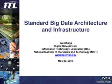
Data Center Cabling TopologyCarriersEntrance Room(Carrier Equip &Demarcation)Offices,Operations Center,Support RoomsBackbone cablingHorizontal cablingTelecom Room(Office & OperationsCenter LAN switches)Horiz Dist Area(LAN/SAN/KVMSwitches )Horizontal cablingZone Dist AreaHorizontal cablingEquip Dist Area(Rack/Cabinet)CarriersMain Dist AreaBackbonecablingComputerRoom(Routers, BackboneLAN/SAN Switches,PBX, M13 Muxes)Backbone cablingHoriz Dist Area(LAN/SAN/KVMSwitches )Horizontal cablingEquip Dist Area(Rack/Cabinet)Horiz Dist Area(LAN/SAN/KVMSwitches )Horizontal cablingEquip Dist Area(Rack/Cabinet)
Distributed Topology with Multiple ERsPrimary EntranceRoomCarriers(Carrier Equip &Demarcation)Horizontal cablingMain Dist AreaHorizontal cablingEquip Dist Area(Rack/Cabinet)CarriersHoriz Dist Area(LAN/SAN/KVMSwitches )Horizontal cablingEquip Dist Area(Rack/Cabinet)BackbonecablingBaca ckbbl onin egHoriz Dist Area(LAN/SAN/KVMSwitches )Horizontal cablingEquip Dist Area(Rack/Cabinet)SecondaryEntrance Room(Carrier Equip &Demarcation)Backbone cablingnecablinggbli ne caBackboBbona cklingne cabBackboZone Dist Area(Routers, BackboneLAN/SAN Switches,PBX, M13 Muxes)Backbonecabling(Office & OperationsCenter LAN switches)Bacca kbobl nin egTelecom s,Operations Center,Support RoomsHoriz Dist Area(LAN/SAN/KVMSwitches )CarriersComputer RoomHoriz Dist Area(LAN/SAN/KVMSwitches )Horizontal cablingEquip Dist Area(Rack/Cabinet)
Backbone TopologynnnnnnIncludes cabling from MDA to ER, HDA, TROptional cabling between HDAs allowedMaximum backbone cable lengths based onapplications distancesCentralized optical fiber cabling supported withinterconnect, splice, or pull-through at the HDAStar topology with no intermediate cross-connectsVarious topologies permit redundancy andflexibility to support various data center sizes
Horizontal TopologyDefined as cabling from horizontal crossconnect (HC) to the equipment distributionarea (EDA)n Star topology with termination on HC inHDA or MDAn Max of one consolidation point in a ZDAn
Horizontal and Backbone CablingnRecognized Cables:Fa) 100-ohm twisted-pair cable (ANSI/TIA/EIA568-B.2), category 6 recommended(ANSI/TIA/EIA-568-B.2-1)Fb) multimode optical fiber cable, 50/125 micron(ANSI/TIA/EIA-568-B.3) and 62.5/125 micron or50/125 micron (ANSI/TIA/EIA-568-B.3)Fc) singlemode optical fiber cable (ANSI/TIA/EIA568-B.3)Fd) 75-ohm (734 and 735 type) coaxial cable(Telcordia Technologies GR-139-CORE)
Carrier Circuit Lengths in Data CentersMaximum cable lengths for common circuits:n E-1’s over 24 AWG Cat 5/5e/6 UTP:532 ft (152 m) - 16.4 ft (5 m) per patch panelnT-1’s over 24 AWG Cat 5/5e/6 UTP:731 ft (223 m) - 16.4 ft (5 m) per patch panelnE-3’s over 734 coax:618 ft (188m) – 19.8 ft (6 m) per patch panelnT-3’s over 734 coax:513 ft (156m) – 15.4 ft (4.7 m) per patch panelDistances are from carrier demarcation point toend equipment and assume no customer DSX.
Carrier Circuit Lengths in Data CentersnnnnCommon data center configurations include 6patch panels: 1 in ER, 2 in MDA, 2 in HDA, and 1in the EDACat 3 instead of Cat 5 reduces circuit lengths forT-1s and E-1s significantly735 coax (mini-coax) reduces circuit lengths forT-3s, E-1s, and E-3s significantlyCircuit length restrictions may :uuurequire additional ERs,limit location of telecom equipment,limit the size of the computer room
Computer Room RequirementsnnnnnnnnnSimilar to Equipment Room reqts from TIA-569Min clear height of 2.6m/8.5 ftMin door size 1m/3ft wide 2.13/7ft highMin dist floor loading 7.2 kPA/150lbf/ft2,recommended min 12 kPA/250 lbf/ft2Dedicated HVAC system preferred20oC to 25oC40% to 55% relative humidity (reduces ESD)Signal reference grid –equipotential groundreference and reduces stray high frequency signalsAny sprinkler systems must be pre-action system
Entrance RoomnnnDemarcation to carriersTelecom Entrance & Campus ConduitsCarrier Racksu Coordinate power and space requirements witheach carrieru Provide either AC or DC power to carriers.u If ER only has AC power, carriers install DCpower from rectifiers to their racks & cabinetsnPlywood for protectorsu Not required if no copper entrance cables or ifcarrier will install protectors on frames or racks
Entrance RoomER may be inside data center but, locationoutside data center provides best securityn ER may be consolidated with MDAn ER requires the same redundancy for powerand cooling as the computer room spacen Locate ER to avoid exceeding maximumcable lengths for circuitsn Cabling distances for carrier circuits maydictate multiple ERs in large data centersn
Main Distribution AreaLocation of Main Cross-Connect (MC), thecentral point of distribution for data centerstructured cabling systemn Centrally located to avoid exceedingmaximum distance restrictions (typically forE-1s, E-3s, T-1s and T-3s)n Install separate racks for Fiber, UTP, andcoaxial cable distributionn
Main Distribution AreannnnData center size may dictate use of Cat 5e or 6UTP for Fractional T-1, E-1, T-1, ISDN PRICopper-pair cabling for LAN backbone cabling (insmaller data centers) and out-of-band managementusing Cat 5e or 6 UTPAT&T 734-type 75 ohm coaxial cable for E-1,E-3, T-3 cabling (two coax per circuit)Multimode and Single-mode fiber cabling for OC3, OC-12, OC-48, MAN, LAN & SAN backbone.
Horizontal Distribution AreaLocation of Horizontal Cross-Connect(HC), the distribution point for cabling toequipment distribution arean Distribution LAN, SAN, KVM switchesand console servers located in HDAn MDA may also include an HC for nearbyequipment distribution arean Number of HDAs depends on the density ofcabling and the size of the data centern
Horizontal Distribution AreannnThe capacity of the cable tray system and the sizeof the cross-connect creates practical limits on thesize of the HCGuideline is maximum of 2,000 4-pair UTP orcoax cable terminations per HDAArrange patch bays to minimize patch cablelengths and to simplify cable managementu Separate racks for fiber, UTP, and coaxu Locate switches and patch panels to minimizepatch cord lengths
Zone Distribution AreannnnnnnRack, cabinet, or under floor enclosure that housesa zone outlet (ZO) or consolidation point (CP)ZO - structured cabling termination for floorstanding equipment that cannot accept patchpanels (e.g. mainframes and large servers).CP - intermediate termination point (e.g. cablingto areas where floor plan is uncertain or dynamic)No cross-connects within the ZDANo active equipment shall be located in the ZDAMaximum of 144 connections in a ZDAMaximum of one ZDA within a horizontal cablerun
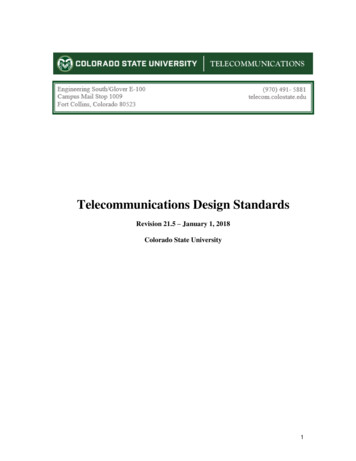
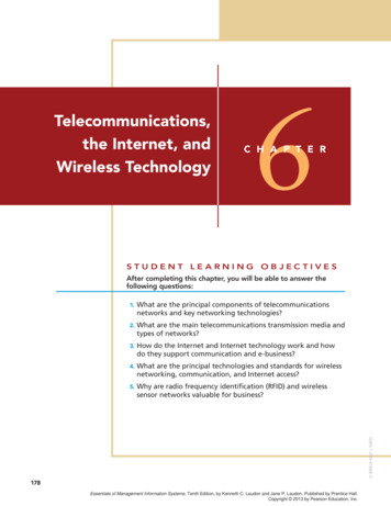
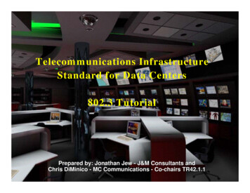
Equipment Racks & CabinetsnnnnCabinets and racks should be arranged in analternating pattern (with fronts of rows ofcabinets/racks facing each other) to create hot andcold aislesCold aisles are front of racks/cabinets – if there isa raised floor, PDU cables are run here on the slab.Hot aisles are rear of racks/cabinets – cable traysfor telecom cabling are typically placed here.Perforated tiles should be placed in cold aisles.
E TRAYSPOWER CABLESFRONTREARREARFRONTFRONTREARHOT AND COLD EQUIPMENT AISLESPREFORATEDTILESTELECOMCABLE TRAYSPOWER CABLES
Equipment Racks & CabinetsnnnnEquipment is mounted in racks & cabinets fromthe front – provide adequate clearance forinstallation of equipment (minimum of 3 feet, 4feet is recommended).Cabinets should be aligned with one edge alongthe edge of the floor tile.Arrange cabinets and racks on raised floor topermit tiles along the front and rear of the cabinetsto be liftedFloor tile cuts should be no
09.07.2003 · n The standard will become TIA-942 n To be submitted for approval by ANSI and CSA. Status of the Standard n 2nd draft released for industry ballot July 2003. draft released for industry ballot July 2003. n Draft posted to IEEE website n Ballot comments to be resolved October 2003. n Liaison with other standards organizations (IEEE, CENELEC, BICSI, ISO,ASHRE) n Liaison with data center