Transcription
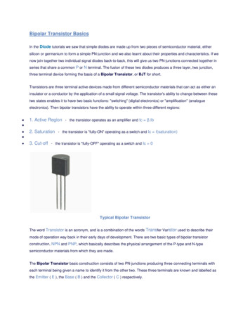
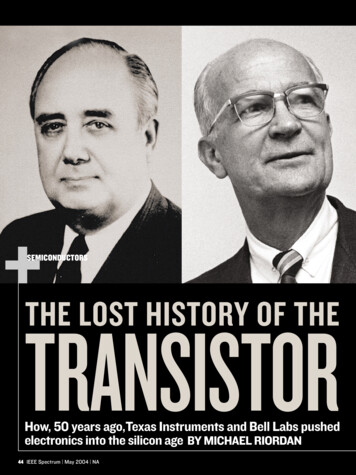
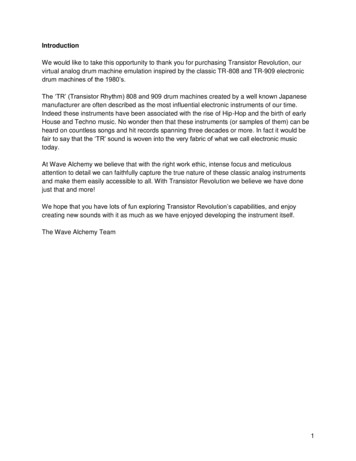
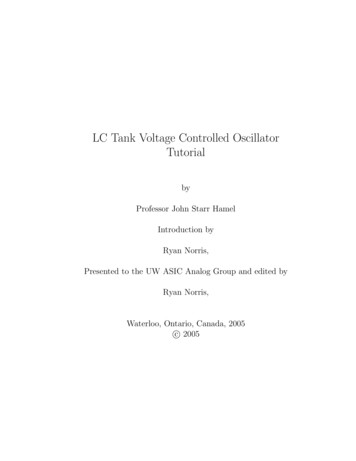
Transistor Measurements With The HF-VHF BridgeGEORGE P. McCASLAND, S a l e s E n g i n e e rparameters of transistors over a widerange of bias and frequency conditions.The RX Meter is well suited to transistor measurements because its bridgeelements will pass, directly, a current ofup to approximately 50 milliamperes,and its two-terminal measurements canfurnish the parameters for radio-frequency transistor circuit design. Contributing to the ease with which transistor measurements can be made arethe self-contained design of the instrument, with the signal generator, bridge,and detector in a single, compact package, and the fact that the “unknown”terminals are located on the flat, tQpsurface of the instrument, where attachment of the measuring jig may be conveniently made.cAFigure 1 . The author is shown measuring a transistor, using the R X Meter, a battery power supply,and a specially made transistor measuring jig.IntroductionThe very high-power efficiency atlow-power levels together with the reliability and low-cost potentials of thetransistor have led to increased usage ofthis device by circuit designers in boththe commercial and military fields ofelectronics. Hearing aids, portabledios, phonographs, dictating machines,porta& cameras, machine-tool controls,clocks, and watches are but a few examples of the commercial applicationsof transistors. A with many otherYOU WILL FIND.Transistor Measurements with. . . .the HF-VHF Bridge . . . . . . . . . 1Meet Our Representatives . . . . . . . . . . . . .6Editor’s Note . . . . . . . . . . . . . . . . . . . . . . . . 8applications, the military have employedthe transistor in the “Explorer” and“Vanguard’ satellites now circling theearth.As the usage Of the transistor increases it is apparent that there is a needtomeasuring techniques.The transistor circuit designer can nolonger get by with specifications published by transistor manufacturers alone;(Normally, the manufacturers will specify transistor parameters for a given setof bias conditions and a single frequencyonly.) he is now often faced with theproblem of determining parameters for.a wide range of bias and frequency conditions. This article describes a transismeasuring technique, using the RXMeter and certain hybrid equations,which will yield information about theThe idea of using the RX Meter fortransistor measurements is not a newone; a number of research, development,and production groups have been engaged in this type measurement forsome time. For example, Messrs. Earhart and Brower of Texas Instrumentsrecently used the RX Meter to measurea new VHF silicon transistor.4 Becauseof the lack of published information onthe theory an2 Practice of transistorFigure 2. Jig hila, shown, includes binding poststo which the 103-A series coil or other componenfs may be connected for extending the RXMeter capacitance, inductance, or resistancerange.
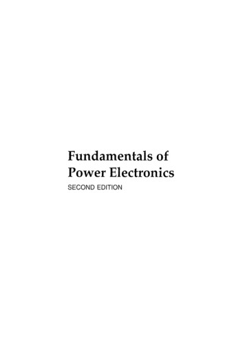
BOONTONT H E BRC NOTEBOOK is publishedfour times a year by the Boonton RadioCorporation. It is mailed free o f charget o scientists, engineers and other interested persons in the communicationsand electronics fields. T h e contents maybe reprinted only with written permission f r o m the editor. Your commentsa n d suggestions are w e l c o m e , andshould be addressed to: Editor, T H EBRC N O T E B O O K , Boonton RadioCorporation, Boonton, N . J.measurements with the RX Meter, however, it has been found that few of thesegroups are using the RX Meter to thelimit of its capabilities, This article isintended to fill the gap in the literature,and at the same time, promote a morecomplete understanding of the use ofthe RX Meter for measuring transistorsby persons currently using the instrument for this purpose, and by those persons unaware of its transistor-measuringapplication.TABLE ICOMMON-BASE tly shown in Table 111.To obtain common-emitter or common-collector h parameters a set ofsimple conversion formulas can be used.As an example, we can convert h 2 2 b tohZzewith the formulahibh i IbhobThe above formula and other conversion formulas are given by Scher6. Theseformulas yield approximate values.Determining the Hybrid ( h )ParametersThe h parameters can be determinedby solving the hybrid equations. Byarbitrarily open- and short-circuitingpairs of terminals in ( 1) , a current ora voltage can be made zero to aid inthe solution. Parameters hll, h22, h21,and h12,are numerically evaluated withthe help of RX Meter measurements.The method of evaluation is outlined inTable I1 below.RX Meter JigsThe RX Meter measurements indicated in configurations A through D inTable I11 require the use of four jigswhich attach the transistor to the R XMeter and supply proper dc bias. Thesejigs can all be operated from a commonpower supply. A schematic diagram ofthe jigs with a transistor in the socketis shown in Figure 3. Each diagramTransistor ParametersTABLE IIConsider the following networkequivalent of the transistor.SOLUTION OF THE HYBRID EQUATION(Assuming Common-bare iona -e2 0Input impedance with output short-circuited,h a -i, 0Reverie voltage transfer ratio with input open-circuited.ez 0i, 0hi/INPUTLinear ,equations can be written usinga set of independent variables to relateel, ez, il and i z ; the independent variables being the input, output, and transfer characteristics of the transistor commonly known as the transistor parameters. These transistor parameters areconstants for a given set of bias andfrequency conditions. One of the mostpopular and most widely used sets oftransistor parameters is the hybrid or hset of parameters. The linear equationsfor the transistor, represented by network ( l ) , in terms of hybrid parameters are:where the h parameters are h l l , hzz,,512, and hzl. The choice of number subscripts here is based on personal preference. IRE Standards3 suggest the useof either number or letter subscripts, asconvenient. Table I is a. cross-referenceof number and letter subscripts assuming a common-base transistor configura-tion.*/Ihtlb hub3- ccI -IForward short-circuit current transfer ratio with output short-circuited.IOutput adminonce with input open-circuited.e*The various circuit conditions foreach h parameter refer to the ac circuitonly. DC bias voltages are not disturbedwhen the ac circuit conditions arechanged. From Table I1 it should beobvious that an input measurement onthe RX Meter provides hllb directly. Byconverting an output RX Meter measurement to an admittance, hzza is alsoobtained directly.Parameters h2lb and h 1 2 b relate voltages and currents on both inpdt andoutput sides of the network providingthe network transfer characteristics. Theh z l b parameter is found numericallyfrom the ratio of two input impedancemeasurements. Parameter hlZb is foundfrom the product of the difference oftwo output admittances and the ratioof hllb over -hZlb. The derivation ofhzlb and h 1 2 b is given in the appendix.In summary, the method of obtainingthe common-base h parameters fromRX Meter measurements is simply and2represents one of the configurationscorrespondingly marked A through Din Table 111.The specific jigs described in thisarticle were designed for a RaytheonType 2N417 PNP transistor for measurements in the 20-mc range. The0.01 pf ceramic by-pass capacitors, powersupply, and jig socket selections all reflect the transistor to be measured andthe approximate frequency range. Theby-pass capacitors have good by-passingaction in the 20-mc range and the jigsperform well in this range. For frequencies appreciably different from 20mc, different capacitors may have to beselected. At frequencies approaching250-mc the jig series inductance mayrequire evaluation. However, no seriousproblems are anticipated in using similar jigs over the entire 500-kc to 250-mcrange of the RX Meter.Since the power supply (Figure 4 )has high resistance in the emitter bias,I
THENOTEBOOKkl,LlTypical Measurementsand CalculationsRX M E T E RTo illustrate transistor measurementsthe common-base h. parameters of aRaytheon Type 2N417 transistor havebeen determined for the following conditions using the RX Meter and the jigs.H1o-yTiPOWER SUPPLY'"Figure 4. Power Supply Schematic-6 voltsi, 5 ma.VcnWhen converting from the parallelequivalents to the rectangular form ofimpedance, a series-parallel conversionchart such as is found in the RX MeterInstruction Manual is of help. In working with the data in Table IV, it wasconvenient to divide the parallel equivalents by 20 to enter them into the chartand to multiply the series equivalentanswers by 20 after removing the valuesfrom the chart. To use the chart properly, a given combination of R, and C,must both be divided by and the answersmultiplied by the same number. Anordinary reactance chart was used inconverting C, readings to reactance.Using jig B of Figure 3 to make theRX Meter measurement necessary toobtain h z z b , the input circuit of thetransistor is effectively open-circuitedf 20mcRX METERR X METER(C)dH1---vlThe four necessary RX Meter measurements (one measurement in each ofthe four jigs) and necessary conversionsto rectangular and polar impedance andadmittance coordinates are shown inTable IV.RX Meter readings are the parallelRp and C, equivalent of the unknownand can be readily converted to rectangular and polar impedance forms.Readings are converted to rectangularadmittance by taking the reciprocal ofthe RX Meter parallel equivalents expressed in ohms. The reciprocal of R,is the conductance G and the reciprocalof XC, in ohms is the susceptance B,where G and B are in ohms.TABLE 111RX METERParameterRequiredFormulaRX Meter MeasurementsUnits(RP) (XCp)Ro 4XCo111hmRDFigure 3. Jig SchematicsXCDhiibcircuit, the power supply resistance LAtermines the emitter bias current andbias will be a constant as different transistors are plugged into the jigs. Use ofthe 90-volt bias battery permits sufficient bias to be developed even withthe hZzb jig which has a fixed 10kresistor in the emitter circuit.The socket used in our jigs accommodates the transistor type with four pinsmounted on a 0.200-inch diameter circle.However, the jigs can be modifiedslightly to accommodate sockets for different type transistors, including thenew universal transistors sockets.As a special feature, the h l l e andhllb- jigs utilize Q Meter binding postsin parallel with the RX Meter terminalsfor use in extending the RX Meterranges.A drawing showing construction details of the jigs is being prepared. Interested persons may obtain a copy bycalling or writing Boonton Radio Corporation, or one of our representatives.Configuration A belowOhmshllb-hrla - cc- 1h,,-h,,a(YZZ - h m )hiib - htibIOhmsConfiguration 6 belowMognitude andphose angleConfiguration A & C belowMagnitude andphose angleConfigurotians A, B, C, 8 D belowrnRX M E T E RYields h, ,b (See formula above)(A)1mRX METERYields hzlb(See formula above)(&I3
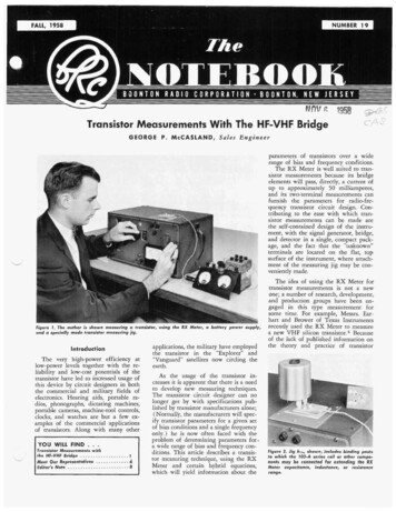
BOONTON1.21 xhlzbiop3 / -32"h22b (0.505 jl.80) xFrom Table 111:hzlb -a -In preparation for a measurement,the RX Meter is balanced as usual witha jig attached to the terminals but without a transistor in the socket. The useof the jigs does not in any way interferewith normal operation of the RX Meter.With normal bridge operating conditions, the voltage appearing a t the RXMeter terminals may be 100 to 500mhos(2 1)--jApplication of the h ParametersThe maximum power gain for the2N417 in the common-base configuration can be readily calculated assumingconjugate input and output impedancematching and lossless neutralization7.A summary of the h parameters measured and calculated for the 2N417 transistor are given in Table V.RX Meter Operating Techniques 65 - j66 ohmsCORPORATIONcapacitance, inductance, and resistanceranges. RX Meter range extension isexplained in detail in the InstructionManual and in a previous Notebookarticlez.with a 10k resistor. To test the effectiveness of this open circuit, 7.5k and 4.7kresistors were substituted for the 10kresistor, while constant emitter bias wasmaintained, without materially changing the RX Meter's indication of output admittance.The target of this example is the fourcommon-base h parameters. From TableI v hllb and h22b are directly availablein rectangular impedance form.hllbRADIO(h21b)P. G. 4hllbrh22br-2Re(h12b h21b)In this equation, h l l b r and h22br arereal p a r t s of hllb a n d h22b a n dRe ( h l z b h 2 1 b ) is the real part of theproduct of h21b and hzlb. The valuesTABLE IVRX Meter ReadingsJig -(-j- 60.7130 9.0 14.3620198093 / - 4 5 " ') - j.56 - - ( .74 - j.56)- - (0.93 / -37") - a 0.93 / 143"Again from Table 111:-hzibInserting values from Table IV, thefollowing calculations are performed. [( 1.61 j 1.31)- ( S O 5 j 1.80fl( 10-3)293 / - 4 5 "93 / -37"Rectangular ZRectangular Yohmsohms13193 /--4501.610.5051- 10-3 mhos1 21x13110-3132"-x 10-3 - 2 (.403 x 10-3).864 / 286"-66 ohms093/1430x 10-3 - ,806 x 10-33 6 4 / 286"130.194 X 10⁻³Power Gain 6.62 [ 286" 6.62ments to obtain the data presented inTable V, good operation of the RXMeter was obtained at actual measuredterminal voltages of 5 to 25 millivolts.The RX Meter measurements did notvary over this voltage range, indicatinglinear operation of the transistor for thisrange of signal level.The author wishes to express hisappreciation to Mr. D. E. Thomas ofthe Bell Telephone Laboratories for hisvaluable assistance in connection withthis work.The Q Meter binding posts on theand hlla jigs provide for easy connection of Type 103-A Inductors and1) Mennie, John, H., "A Wide RangeVHF Impedance Meter", The Note.hllegood commercially available capacitorsand resistors to extend the RX Meter4LJ,864 / 286"131(0.505 XI 1 80) j 1.80(.93/ 143")2P. G. 4 x 65 X ,505 X 10W3 - 2 Re(1.21X 1 0 - 3 / - 3 1 " X . 9 3 / 1 4 3 " )Numerical Value65 - 1 i1.13ftom Table V are substituted in theformula for power gain and the necessary calculations are performed.TABLE VParameterohms65-i66 i885 i556MEASURED AND CALCULATED h PARAMETERSPolar 2153*/-l44-i52millivolts or more. This is sufficient, inmany cases, to drive a transistor beyondits linear range of operation. The terminal voltage, however, may be reducedto 20 millivolts or, in some cases lessthan 20 millivolts, by reducing the levelof the oscillator output with a seriesresistor in the oscillator B lead. (Seepage 16 of the Instruction Manual andNotebook #62.) During the measure-153 [ 200"- - (-.26hlzb i454130- - (.61 /-245"hlzb1686201980Values of polar coordinates from TableIV are substituted in this equation andthe following calculations are performed.-aCp (ohms) 17.5A(hd(hndRp (ohms)168C (hiidD( m fParallel EquivalentCP (Wf)Rp (ohms)BIBLIOGRAPHYbook, Summer 1954, No. 2 .2 ) Riemenschneider, Norman L., "Some\'r
THENOTEBOOKVHF Bridge Applications”, T h eNotebook, Summer 1955, NO. 6.“IRE Standards on Letter Symbolsfor Semi-Conductor Devices”, Proceedings of IRE, July 1956, Page 934.Earhart, Charles and Brower, William, “70MC Silicon Transistor”,Semi-Conductor Products, MarchApril 1958, Page 14.R i e m e n s c h n e i d e r , N o r m a n L.,“Transmission Line Measurementswith the RX Meter”, T h e Notebook, Fall 1954, No. 3.Scher, Sol, “Rapid Conversion of’Hybrid Parameters”, Electronics,March 28, 1958, Page 75.7 ) Linvill, J. G. and Schimpf, L. G.,“The Design of Tetrode TransistorAmplifiers”, Bell System TechlzicalJournal, Volume 35, July 1956,Pages 813-840, equation 1.(4)hllb ?I-:el-7when e2 0 by definition.Substituting i, for il in ( 5 ) , sinceil i, from ( 4 )el 7(6)fieThe transistor is now redrawn schematically in the common-emitter configuration.THE AUTHORGeorge P. McCa3and joined the BRCstaff as Sales Engineer in January, 1958.From 1954 to 1957 he was associatedwith the Esso Standard Oil Co., holdingposts with Electrical Engineering andBudget Groups of that company’s BatonRouge Refinery.Mr. McCasland received a BEE degreewith a Communications Option fromthe University of Virginia in 1952 anda masters degree in Industrial Management from M.I.T. in 1954.APPENDIXDerivation of hzland h,, Formulash2ibThe elementary current relationshipsof the junction transistor are shown inthe following schematic diagram:where: i, i, (7)where: il -ib -( 1-Now, by definition, hll, a )-ie (1-el-.whenile2 0.(8)Substituting the equalityil - (1--cc) i, shown in(7).;elhll, y ( 1 - a ) ie ( 9 )elhllb -, repeating ( 6 )ieBy examination of ( 6 ) and ( 9 ) , wesee that if hll, of ( 9 ) is multiplied by-( 1- a ), the product will be equalto hllb of ( 6 ) as expressed in (10) a ze fib i,(3)The transistor is redrawn substitutingfor i, from equation (1) and i,(1-a ) for ib from equation ( 3 )and short-circuiting the output circuitin ( 4 ) . The dotted box symbolizes the-networkfor which network currentil i, and i 2 -a i,.cc i,Now the transistor is drawn asnetwork, ( 1 7 ) , and by definition:a 2h22a - -, where il 0(16)e2The negative sign in (16) stems fromnetwork convention, where i 2 is shownflowing toward the network but actuallyflows in the opposite direction (outward from the network) for the common-basetransistor circuit configuration.Referring to ( 1 7 ) , the input to thenetwork can be shorted reducing el tozero. By definition:ibE )The open circuit input voltage, el,can be assumed to be caused by a v01tage generated within the network,which in this case is a voltage transferred back from the output circuit.2 is the short-circuit input impedance,a part of Thevenin’s concept. Sincehllb is the short-circuit input impedanceof (13), it can be substituted for 2.The input can then be short-circuitedand the result shown in ( 1 5 ) , where:el hllbili,.by Kirchoff‘s law (1)i, a i, by definition.(2)Substituting ( 2 ) in ( 1) :i, a ie. .i b9(13)INPUTilhllbBy ‘Thevenin’s Theorem, the input tothe network can be represented asshown below.h 1%For the transistor network shown below, representing a transistor in thecommon-base configuration, the reversevoltage transfer ratio by definition is:5y22b - -,when el 0. (18)e2In equation ( IS), Y22b is one of theadmittance family of parameters. If the
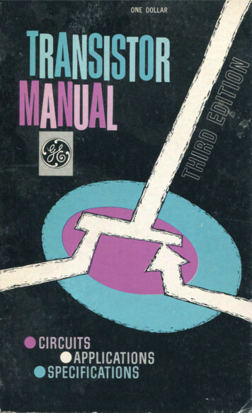
BOONTONi2- h22bZZ---e2short-circuited input admittanceappearing in the outputNow:h21b -ECORPORATIONwhen il flows and e l is the generatedfeedback voltage which does not appear dat the input terminals for the shortcircuited case.In measuring h parameters it is assumed that all measurements are performed at signal levels for which thetransistor is a linear network.If the short-circuit of (14) is removed, el will appear across the inputterminals and at the same time il willgo to zero. Therefore, equation (23)holds when il is zero as well as when ilis flowing.open-circuited output admittance, h 2 2 8 ,is subtracted from the short-circuitedoutput admittance Y 2 2 b , the resultantoutput circuit admittance is that due tothe current flowing in the short-circuitedinput circuit, or in other words, to theshort-circuit input admittance. This relationship is shown in (19), where:Y22hRADIO(19)i2zil(Y22bPh22b)h110el-- -- h12b,-h210e2when il is zero.M E E T O U R REPRESENTATIVESEARL LIPSCOMB ASSOCIATESHARRY J . LANG, S a l e s M a n a g e rFounded by Earl Lipscomb in 1947,Earl Lipscomb Associates of Dallas,Texas, is the only engineering salesrepresentative organization in theSouthwest specializing exclusively inthe field of electrical and electronic instrumentation. The company maintainsoffices in Dallas, Houston, and El Paso,and offers complete technical serviceto customers in Texas, Oklahoma, Arkansas, Louisiana, and Mississippi.Radio and electronics are not newto Earl Lipscomb, the company’s President; he has been active in the fieldsince 1937 when he began as a consulting engineer. During World War11, he served in the training, production,and procurement phases of the Navy’selectronic program. His five-year tourof duty included training at the NavyRadar School at M.I.T., and service withNavy Bureau of Personnel and theNavy Materiel Division. Upon completion of Navy service in 1947, hefounded Earl Lipscomb Associates. InMay of that year, Boonton Radio Corporation, recognizing the growing needfor electronic instrumentation by customers throughout the Southwest, waso n e of t h e f i r s t c o m p a n i e s t o e n g a g e t h e s e r v i c e s of t h e n e w l yformed organization.L‘-Earl LipScombAs the needs of the electronics industry expanded, so did the facilities andservices of Earl Lipscomb Associates.The modern building, which houses theDallas headquarters, comprises over 10,000 square feet of office and shop spaceand includes a complete clerical staffengaged in the distribution of technicalinformation and processing of customer6orders. Modern, well-equipped servicelaboratories at the Dallas and Houstonlocations provide calibration and repair Lservice for all of the products manufactured by thirteen leading producers ofprecision electronic equipment. Thesefacilities are staffed by six factorytrained service engineers.A special group of five sales engineers, with specialized training in electronic measuring techniques, and twoengineering trainees devote their entireeffort to the solution of customer problems. This group is equipped to providedemonstrations of all equipment in thecustomer’s laboratory; having at its disposal a unique “laboratory on wheels”known as the Travelab’. This mobile1a b o r at o r y , w h i c h trave Is r e g u 1a r 1ythroughout the Southwest, is completelyequipped to provide operating demonstrations and serves to keep the customers abreast of the latest in instrument design and application.It is the objective’of Earl LipscombAssociates to not only provide the customer with the proper instrumentationfor his specific needs, but also to insurethat these products continue to providereliable service. For their constant effort toward this end, and for their recordof efficient and faithful service to ourcustomers, BRC extends a vote of thanks 4to Earl Lipscomb Associates.
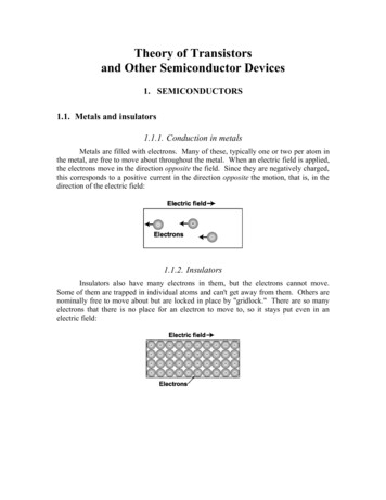
THENOTEBOOKThe T r a v e l a b " , carries a full line of instruments t o the customers' laboratory ar plant.MODIFICATION OFTYPE 202-F SIGNAL GENERATORIn order to provide equipment whichis compatible with the recent extensionof the telemetering band to 260 megacycles, BRC announces the availabilityof a modified version of the 202-FSignal Generator, on special order, withan overall frequency coverage of 195to 270 megacycles. BRC will also modifyexisting 202-F Signal Generators currently in the field. Please call or writeyour sales representative or BoontonRadio for full particulars.GENE FRENCH COMPANYAPPOINTED SALES REPRESENTATIVEW e are pleased to announce that, effective July 1, the Gene French Company has been appointed BRC sales representative in the New Mexico, Utah,and Colorado area. The company maintains offices in Albuquerque and Denverand is fully equipped to handle sales,application engineering, and service forall BRC products."Gene", who has previously handledBRC instruments in New Mexico, ishandling that area. "Hugh' Hilleary isheading the new Denver office. Pleaseti-.u d o not hesitate to call upon them forHugh Hillearyinformation or demonstrations.7
BOONTONRADIOCORPORATIONTHENOTEBOOKEDITOR’S N O T EAmateur radio has given thrills andpleasures to countless thousands of persons the world over. Few people realize,however, that this favorite pastime isalmost as old as the art itself. Therewere radio amateurs before the beginning of the present century; not toolong, in fact, after Marconi astoundedthe world with his invention of wirelesstelegraphy. But amateur radio came intoits own when private citizens discoveredthis means of personal communicationwith others and set about learningenough about “wireless” to build homemade stations. Its progress since thoseearly days has been remarkable. In thefirst years, amateurs were stuck with 200meters and could barely get out of theirbackyards. Today, with years of experimentation under the amateur belt, international DX is a reality and QSOs withcountries all over the world are commonplace.Personal communications betweenHAMS is only part of the amateur radiostory. These “home stations” have posteda brilliant record of public service.Amateur cooperation has played an important part in the success of many anexpedition and, in many cases, has beenthe only means of outside communication during several hundred storm, flood,and earthquake emergencies in this country. These public service endeavors wereso successful in fact, that in 1938 theAmerican Radio Relay League ( ARRL)inaugurated a new emergency-preparedness program, registering personnel andequipment in its Emergency Corps andputting into effect a comprehensive program of cooperation with the Red Cross.contributions to the art. During WorldWar 11, thousands of skilled amateurshelped to develop secret radio equipment for both Government and privatelaboratories. In the prewar years, technical progress by amateurs provided thekeystone for the development of modern military communications equipment.Modern radio owes a lot to theseindefatigable amateurs for their contributions to the art. W e are proud tonumber among their lot eight of BRC‘semployees.The HAM and amateur radio is constantly in the forefront of technicalprogress too. Amateur radio developments have come to represent valuableL. 0. Cookex - 8BRUK2LTHV. E. HoplerG. A. SanfordK2ARWN. L. Riemenschneider W2LKOG. P. McCaslandK2RLKN. L. Greendykex - W2KSRD. M. TerpKN2 JTNJ. P. Van DuyneW2MLX-gALBUQUERQUE, N e w MexicoGENE FRENCH COMPANY120 San Pedro Drive, S. E.Telephone: AMherst 8-2478TWX: AQ70ATLANTA, GeorgiaEIVINS a CALDWELL3133 Maple Drive, N.E.Telephone: CEdor 3-7522TWX: AT 987BINGHAMTON, N e w YorkE. A. OSSMANN 8 ASSOC., INC.147 Front StreetVestal, New YorkTelephone: ENdicott 5.0296BOONTON, N e w JerseyBOONTON RADIO CORPORATIONlntervale RoadTelephone: DEerfield 4-3200TWX: BOONTON NJ 866BOSTON, MassachusettsINSTRUMENT ASSOCIATES1315 Mossochusettr AvenueArlington 74, Moss.Telephone: Mlssion 8-2922TWX: ARL MASS. 253CHICAGO 45. IllinoisCROSSLEY ASSO‘S., INC.271 1 West Howord St.Telephgne: SHeldroke 3-8500TWX: CG 508DAYTON 19, OhioCROSSLEY ASSO’S., INC.53 Pork AvenueTeleohone: Axminster 9-3594TWX: DY 306HOUSTON 5, TexasEARL LIPSCOMB ASSOCIATESP. 0. Box 65733825 Richmond AvenueTelephone: MOhowk 7-2407DENVER 9, ColoradoGENE FRENCH COMPANY529 East Ohio AvenueTelephone: PEarl 3-2742TWX: DN 106-UHUNTSVILLE, A l a b a m aBlVlNS & CALDWELLTelephone: JEfferson 2-5733(Direct line t o Atlanta)EL PASO, TexasEARL LIPSCOMB ASSOCIATES720 North Stonton StreetKEystone 2-7281INDIANAPOLIS 20. l n d i o n aCROSSLEY ASSO’S., INC.5420 North College AvenueTelephone: CLifford 1-9255TWX: I P 545HARTFORD, ConnecticutINSTRUMENT ASSOCIATES734 Asylum AvenueTelephone: CHapel 7-1 16510s ANGELES, CaliforniaVAN CROOS COMPANY21051 Costanso StreetPost Office Box 425Woodlond Hills, CaliforniaTelephone: Dlamond 0-3131TWX: Conogo Park 7034H I G H POINT, N o r f h CarolinaBlVlNS B CALDWELL1923 North Moon StreetTelephone: Hlgh Point 2-6873TWX: HIGH POINT N C 454ORLANDO, FloridaBlVlNS B CALDWELL1226 E. Coloniol DriveTelephone: CHerry 1-1091/7B O O W O N RADIO(dOTTAWA Ontario, CanadaBAYLY ENGINEERING. LTD.48 Sparks StreetTelephone: CEntral 2-9821PITTSBURGH 36, PennsylvaniaH. E. RANSFORD COMPANY5400 Cloirton BoulevardTelephone: Tuxedo 4-3425ROCHESTER 10, N e w YorkE. A. OSSMANK B ASSOC., I N C830 Linden AvenueTelephone: LUdlow 6-4940TWX: RO 189S A N FRANCISCO, CaliforniaVAN GROSS COMPANY1178 Lor Altos AvenueLos Altos, ColifornioTelephone: WHitecliff 8-7266ST. PAUL 14; MinnesotaCROSSLEY ASSO’C., INC.842 Roymond AvenueTelephone: Mldway 6-7881TWX: ST P 1181SYRACUSE, N e w YorkE. A. OSSMANN & ASSOC., INC2363 James StreetTelephone: HEmpstead 7-8446TWX: SS 355TORONTO, Ontario, ConodaBAYLY ENGINEERING, LTD.First StreetAiox, Ontorio, ConodaTelephone: Aiox 118(Toronto) EMpire 8-6866N E W JERSEYBOONTON-Printed in U.S.A.8
hart and Brower of Texas Instruments recently used the RX Meter to measure a new VHF silicon transistor.4 Because of the lack of published information on measuring a transistor, using the RX Meter, battery power supply, measuring jig. Introduction applications, the military have employed the transistor in the "Explorer" and