Transcription
byInstallation and Maintenance Instructions1Standard and Bushing Style CouplingsIntroductionThe following document is intended for the explicit use of Lovejoy customers to aid in the installationof Lovejoy power transmission products. The information may be considered privileged and shouldonly be disseminated as an active part of conducting business with Lovejoy, Inc.Although the coupling may have been properly specified during the design and selection processbefore the coupling was ordered, operational conditions could possibly have changed prior toinstallation. Lovejoy, Inc. provides the information and technical support necessary to ensure theappropriate coupling selection was made relative to the product specifications and limitationsof Lovejoy’s power transmission products. The end user is ultimately responsible for verifying thesuitability of the final coupling selection based on the actual service conditions at the time of thecoupling installation.VIDEOS AVAILABLEInstallation videos of standard,bushing style and half spacer styleS-Flex Endurance couplings areavailable atwww.lovejoy-inc.com/resourcesCorrect installation and alignment practices will extend the coupling life, support properoperation, and establish a safer operating environment for the coupling. Please thoroughly reviewall of the following instructions prior to installing this coupling and placing it in operation. Safetyguidelines and practices should always be followed during every phase of the installation.1.0 Product InspectionPrior to installation, the coupling should be examined for signs of damage resultingfrom shipping or handling. Refer to the following chart to ensure all the ordered partsare present.Table 1 – Components(Standard S-Flex Endurance and Bushing Style)Flange SizeFlangesSleeve1BushingsCap Screws4J - 6J21n/an/a5S - 16S21n/an/a6B - 16B212 (QD )66T - 16T21Customer Supplied2Notes: 1. Split sleeves may have retaining ring.2. Taper-Lock bushings supplied by the customer.For maximum protection, the coupling and all components should be stored in theoriginal packaging. All parts should be measured prior to installation to ensurecorrectness of parts to meet the application requirements; such as the hub borediameter, shaft diameter, shaft separation, key sizes, etc. The BSE (shaft separation)dimension should be measured from the end of one shaft to the end of the other shaft,not to hub faces or pilots.WARNINGFailure to observe the following warnings could cause thepower transmission product to break and parts to be thrownwith sufficient force to cause serious injury or death.Selection. Do not exceed catalog ratings. Refer to the Lovejoy catalogfor proper selection, sizing, horsepower, torque range, and speedrange of these products.Installation. Proper maintenance, handling, and shop practices arecritical. Follow all installation instructions included with the productand provided by your equipment manufacturer, and all applicablefederal, state, and local regulations concerning the safe operation andmaintenance of manufacturing equipment.Operation. Avoid sudden shock loads during start up and operation.Do not operate a coupling assembly with improper alignment orbolt torque or with damaged or worn elastomeric elements. Inspectthe assembly for these conditions shortly after initial operation andperiodically thereafter.The coupling assembly should operate quietly and smoothly. If thecoupling assembly vibrates or makes a beating sound, shut down theequipment immediately and recheck the alignment.Lovejoy manufactures couplings based on the shaft details provided by the purchaser.Lovejoy is not responsible for inaccurate or incomplete information supplied by thepurchaser. Check all shaft dimensions.It is the responsibility of the purchaser to assure the interface connections (flanges,bolts, keys, hydraulic fits, etc.) between the coupling and connected equipment arecapable of handling the anticipated loads.www.lovejoy-inc.comCONTINUED ON NEXT PAGE
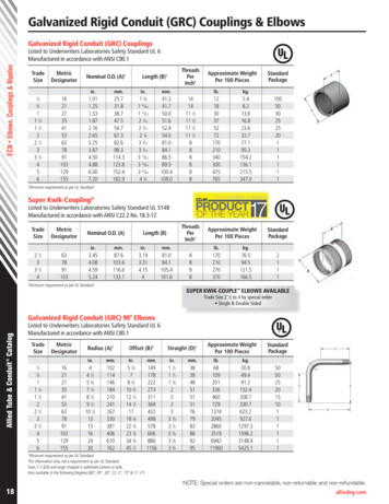
Installation and Maintenance Instructionsby2Standard and Bushing Style CouplingsBefore beginning the coupling installation, make sure the machinery ismade safe. Disconnect and lock out all power to the equipment. No part ofthe installation should be performed on moving, non secure, or unstableequipment.2.0 Required Tools Calibrated Torque Wrench and Allen sockets Alignment Equipment (Calipers and straight edge) Appropriate tooling for repositioning equipment3.0 Coupling and Component Preparation3.1 All exposed surfaces of the coupling and components, including hubs, flanges,sleeves, retaining rings, screws, and any other Lovejoy supplied parts should bethoroughly cleaned prior to installation to remove any protective coatings that may havebeen applied by Lovejoy as corrosion protection during shipping. All coupling parts,equipment components, shafts, and keyways must be clean and free of any foreignmaterials prior to attempting assembly or installation. A clean cloth dampened with anonflammable solvent should be sufficient for this cleaning.3.2 All components, flange bores, shafts, keys, and keyways must be checked for raisedmetal, nicks, burrs, dents, gouges, etc., and should be dressed or repaired accordinglyprior to installation.3.3 Prior to removing any existing coupling, establish and record the Distance BetweenShaft Ends (BSE), between the driver and driven shafts and compare this value withthe BSE dimension for Lovejoy S-Flex Endurance Couplings in Table 5 to verify fit of thecoupling.3.4 Once all necessary measurements have been taken and all components are verifiedas correct, remove any existing coupling and dress the shafts on the driver and drivenequipment.3.5 If the actual shaft BSE is the same as the specified BSE value for the Lovejoy S-FlexEndurance coupling (see Table 5), then the flanges can be mounted flush with the endsof the driver and driven shafts.3.6 If the actual shaft BSE is different than the specified BSE for the Lovejoy S-FlexEndurance coupling, then the flanges must be mounted on the driver and driven shaftsso that the dimension between the flange faces matches the ‘G’ dimension as specified inTable 5.3.7 Lovejoy machines the bore in all Lovejoy S-Flex Endurance style flanges with ‘inch’dimensioned straight bores and keyways to meet the industry accepted ANSI/AGMA9002-B04 Standards’ tolerance for common keyways and clearance fit bores unlessotherwise specified. Tapered and spline bores may require special manufacturing andinstallation consideration.3.8 Lovejoy machines the bore in all Lovejoy S-Flex Endurance style flanges with‘metric’ dimensioned straight bores and keyways to meet the industry accepted ANSI/AGMA 9112-A04 Standards’ tolerance for common keyways and clearance fit boresunless otherwise specified. Tapered and spline bores may require special manufacturingand installation consideration.3.9 Lovejoy machines the bore in all Lovejoy S-Flex Endurance style flanges with taperbores using tolerances and specifications as supplied by the customer. Taper bores willbe tested with plug gauges usually supplied by the customer or included in the cost ofthe coupling.www.lovejoy-inc.com4.0 Coupling Installation4.1 Identify which type sleeve will be used for thisinstallation. The sleeves will be one piece, single split,or two piece split with a retaining ring. The standardblack sleeves are an EPDM material, the blacksleeves with a green dot are neoprene, andthe orange sleeves are Hytrel .4.2 Prior to mounting the hubs, place thekeys in the shaft keyways. The key should fitsnuggly in the keyway with minimal side to side movement.Standard keys should be the same length or slightly longer thanthe keyway in the flange. Woodruff keys are usually shorter and may not transmit thesame amount of torque.Note: If using a standard bushing style flange for QD or Taper-Lock bushings, skip toStep 4.5.4.3 When installing standard flanges, slide the appropriate flange on each of the shaftsover the keys and align the face of the flange with the end of the shaft. Lovejoy S-FlexEndurance flanges are machined with a clearance, or slip fit and should slide onto theshaft with little or no difficulty. Using a calibrated torque wrench, tighten both setscrews in one flange to the torque value specified in Table 2. Lightly tighten the setscrews in the second flange to allow for possible axial adjustments after the equipmenthas been moved.Note: Flanges must be mounted on the driver and driven shafts with the serrationsfacing each other.4.4 If the shaft separation is not equal to the BSE dimension as specified in Table 5,the flanges may need to overhang off the end of the shafts equally on both sides. If theflanges are hanging off the shafts, the amount of shaft engagement in the flange shouldbe equal to or greater than the diameter of the shaft.Note: if NOT using bushings, skip to Step 4.7.4.5 When installing standard bushing style flange, insert the bushinginto the flange and thread the retaining screws into the tappedholes; but, do not tighten the screws until the flanges are mountedon the shafts. Slide the flange onto each of the shafts over the keysand align the face of the flange with the end of the shaft.4.6 Tighten the retaining screws on the bushings evenly usingthe industry standard procedure to the torque specified in Table3. Tighten each retaining screw first to 50% of the specified torque,then 75%, then to the final torque as specified, using a calibrated torquewrench. Tighten screws to the torque value specified in the instructionsprovided with the bushing, or refer to the torque values specified in Table 3. When tight,the flange on the bushing should not come in contact with the S-Flex Endurance flange.There should be a gap between the face of the flange and the bushing of approximately1/8” to 1/4”.DO NOT over tighten the screws on the QD or Taper-Lock bushings. If thescrews are too tight, this could damage the S-Flex Endurance flange.4.7 For couplings with a single piece sleeve, or single split sleeve, insert the sleeve intoone of the flanges prior to moving the equipment together.CONTINUED ON NEXT PAGE
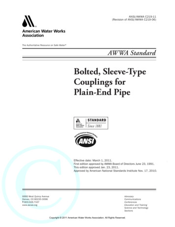
Installation and Maintenance Instructionsby3Standard and Bushing Style Couplings4.8 For couplings with a two piece sleeve and retaining ring, hang the ring in one ofthe grooves around the sleeve, not into the final position. This would inhibit the abilityto perform the alignment inspection. Insert the sleeve into one of the flanges prior tomoving the equipment together.4.9 Carefully move the equipment together until the serrations on the sleeve meshwith the other flange. The face of the flanges should just barely touch the sleeve. If theflanges are pressed too tightly against the sleeve, the coupling will lose some capabilityto accommodate misalignment.4.14 Recheck alignment and tightness on the set screws and bushing retaining bolts(B-Style).4.15 Remove any tooling and material away from the shafting and coupling. Install theappropriate coupling guard per OSHA requirements and remove the Lockout / Tagout kitfrom the power supply. The equipment can then be started up and tested. The couplingand equipment should run smoothly. If vibration is detected it could indicate thereis an issue with alignment or other problems. This could point to problems related tothe motor, coupling, or driven equipment and should be resolved prior to placing thiscoupling into operation.Contact your local authorized Lovejoy sales representative prior to replacingthe sleeve with a material that is different from the original sleeve.5.0 Maintenance (Sleeve Replacement)5.1 Most sleeve failures are signature, or classical types of failures that visually offerclues as to the cause of failure. Always inspect the existing sleeve to ensure there are noobvious equipment issues that could lead to a premature failure of a replacement sleeve.For example, if the serrations are worn off the old sleeve, there could be issues withmisalignment. If the old sleeve is torn, particularly a diagonal tear in the sleeve, thiscould indicate the coupling is being subjected to an over-torque condition. These issueswill need to be corrected prior to placing the equipment back in service.5.2 Loosen the set screws on one flange. Move the flange back on the shaft until thesleeve is free of the serrations in the flange.4.10 Measure the coupling width at the outside of the flanges (see picture above) andcompare with Table 4 to ensure this measurement falls within the X-Min and X-Maxrange. If it falls outside the X-Min and X-Max, realign the equipment to correct thiscondition. ‘G’ should match the value specified in Table 5.5.3 If this is a B-Style flange, loosen the retaining screws that draw the bushing into thetapered bore. You may need to remove two of the screws and reinsert these screws intothe threaded holes in the bushing. When you evenly tighten these screws, they shouldpress against the coupling flange and force the bushing to release. You should then beable to move the flange and bushing back on the shaft until the sleeve is free of theserrations in the flange.5.4 If the sleeve is a one piece sleeve, and is being replaced with a one piece sleeve,separate the equipment until there is enough space between the shaft ends to removethe sleeve.5.5 If replacing the sleeve with a split sleeve, the equipment may not need to bemoved. An existing one piece sleeve may need to be cut to remove the sleeve from thecoupling. A new split sleeve can then be pulled open to allow the sleeve to slip over theshafting.5.6 To reassemble this coupling, start at Step 4.8 of the Coupling Installation sectionand repeat the remaining steps.Check the axial, angular, and parallel alignment to ensure the equipment iswithin the recommended limits for this coupling. This may prevent possibledamage to the coupling or equipment due to stresses placed on the couplingby poorly aligned equipment.4.11 Next, lay a straight edge across the top of the flanges (see pictur
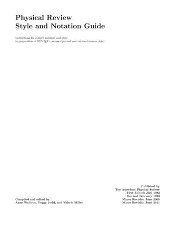
Note: If using a standard bushing style flange for QD or Taper-Lock bushings, skip to Step 4.5. 4.3 When installing standard flanges, slide the appropriate flange on each of the shafts over the keys and align the face of the flange with the end of the shaft. Lovejoy S-Flex Endurance flanges are machined with a clearance, or slip fit and should slide onto the shaft with little or no .