Transcription
Autodesk Fusion 360
Autodesk Fusion 360 training1
Autodesk Fusion 360 trainingInhoudIntroduction . 41.Main User Interface . 52.Data Panel Interface. 73.View Navigation . 84.Workspaces . 105.Design History . 126.Autodesk A360 . 137.Hot Keys . 15Sketching . 168.Create Sketch . 179.Base Sketch . 22Sculpting . 3010.Create a T-Spline Primitive Form . 3211.T-Spline Form Creation – Revolve . 3312.T-Spline Form Creation – Sweep . 3513.T-Spline Form Creation – Loft . 3914.Modify a T-Spline Form . 4115.Add Details to a T-Spline Form. 4816.Delete T-Spline Edge . 5017.Create a T-Spline Form from a Reference Image . 51Solid Modeling . 5918.Create solid body . 6119.Remove geometry for a slot . 6620.Model from a Sculpted body . 68Manage and Collaborate . 8721.Create and Manage Fusion 360 Group Projects . 8822.Create new versions. 9223.Add a user to your project . 9324.Create a referenced document . 952
Autodesk Fusion 360 training25.Access data in a web browser . 9726.Insert designs into other designs . 10927.Share designs . 113Assembly Design . 11628.Move and Align . 12129.Create a Rigid Group . 12230.Joints . 12431.As-built Joints . 12832.Contact Sets . 13233.Motion Study . 134Top-down Design Methodology. 13634.Using existing geometry to drive sketch curves . 13635.Extrude the sketch and interface with other parts . 140Rendering . 14236.Open Fusion360 file and go to Render Workspace . 14337.Apply Materials . 14438.Editing Materials . 14839.Apply A Decal . 15640.Environment Settings . 15741.Rendering . 161Drawings. 16842.Create a Drawing. 16943.Finish the layout:. 17244.Edit the layout views . 17745.Text and Annotations . 17946.Text and Leader Notes: . 18047.Dimensions. 18248.Drawing Settings & Preferences . 18649.Output the Drawing . 189Notes . 1913
Autodesk Fusion 360 trainingIntroductionOverviewFusion 360 is a cloud-based CAD/CAM tool for collaborative product development. The tools in Fusionenable exploration and iteration on product ideas and collaboration within a product developmentteam.Fusion 360 enables fast and easy exploration of design ideas with an integrated concept to productiontoolset. Fusion lets you focus on the form, function, and fabrication of your products. Use the sculptingtools to explore form and modeling tools to create finishing features. These tools let you quickly iterateon design ideas. Once you have settled on a design, you can create assemblies to validate fit and motionin your design or create photo-realistic renderings to verify the appearance. Finally, you need tofabricate your design. Use the 3D print workflows to create a rapid prototype or the CAM workspace tocreate toolpaths to machine your components.Fusion 360 also helps bring design teams together for collaborative product development. All yourdesigns are stored in the cloud, which means you and your team always access the latest data. Fusionalso tracks versions of your design as you work. You can use Autodesk A360 to view each version in yourweb browser and promote an old version to the current version. Finally, use Fusion and A360 to shareyour designs and track design activity. You can even provide controlled access to your designs withoutrequiring an Autodesk ID.Fusion 360 uses a hybrid environment that harnesses the power of the cloud when necessary and useslocal resources when it makes sense and cloud resources. For example, your design data is store on thecloud and renders amazing images every time you save a new version of your design. This happens inparallel while you are creating and editing designs local on your machine. This allows you to harness thepower of your computer and the power of the cloud at the same time.Throughout this course, you explore these areas of Fusion 360. This course will get you started designingwith Fusion and help you understand how it can improve your design processes.4
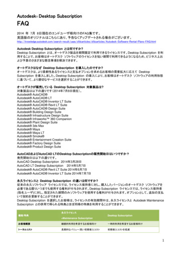
Autodesk Fusion 360 training1. Main User Interface1. Application bar: Data Panel: Display or hide the data panel on the left of theinterface. File: Access file operations such as New Design, Save, Export, and3D Print. Save: Save an untitled design or save the changes to a design asa new version. Undo/redo: Undo or redo operations.2. Toolbar: Access commands in the toolbar.5
Autodesk Fusion 360 training3. Profile and help: Profile name: Access preferences and your Autodesk profile. Help: Access help, forums, and tutorials, what’s new, andfeedback.4. ViewCube: Orbit the view and access orthographic and isometric views.5. Browser: Lists objects in the design.6. Marking menu: Another method to access commands. Right-click to display the marking menu.7. Timeline: List the operations performed on a design if parametric modeling is active.8. Navigation bar and display settings: The navigation bar contains commands to navigate theview. The display settings control the display of the design in the canvas.6
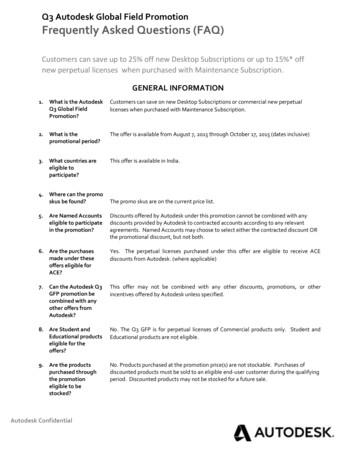
Autodesk Fusion 360 training2. Data Panel Interface1. Project switcher: Select the active project.2. Project tools Project Members: Invite members to the active project. Project details: Opens the active project in Autodesk A360 in your defaultinternet browser. Search: Search the active project or all projects you have access to.3. Data tools Upload: Upload files to Autodesk A360. Many CAD data types are supportedas well as standard files such as documents, spreadsheets, and presentations. Data view: Select how data is displayed in the data panel. Refresh: Refreshes data from Autodesk A360.4. Thumbnails: Right-click a thumbnail to access commands for that specific design.7
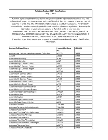
Autodesk Fusion 360 training3. View NavigationCommandsUse ViewCube to orbit the design in the canvas. Drag the ViewCube to perform a free orbit. Click facesand corners of the ViewCube to access standard orthographic and isometric views.Use the commands in the Navigation bar to pan, zoom, and orbit the canvas. The menus on the right endcontrol Display Settings and Layout Grid options.MouseScroll the middle mouse wheel to zoom in or zoom out.SCROLLClick and hold the middle mouse button to pan the view.HOLDSHIFTKEY Hold the SHIFT key and click and hold middle mouse button to orbitthe view.Mac Trackpad2 finger pinch to zoom out.8
Autodesk Fusion 360 training2 finger spread to zoom in2 finger swipe to pan the view.Hold SHIFT and 2 finger swipe to orbit the view.SHIFT 9
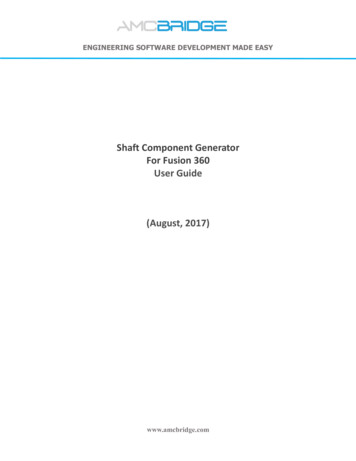
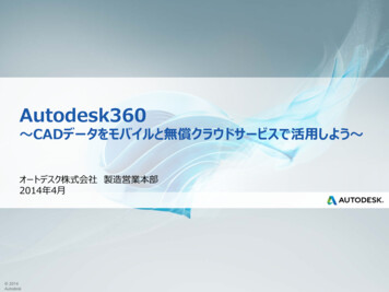
Autodesk Fusion 360 training4. WorkspacesFusion 360 uses workspaces control the commands that are available and the type of data that iscreated. There are multiple workspaces available depending on the work you plan to perform. Sculpt: create organic shapes by manipulating faces, edges, and vertices. Model: create solids with hard edges and flat faces. Patch: create open surfaces to stitch into solid bodies. Render: set up the environment and create photo-realistic renderings. CAM: create and simulate tool-paths then generate g code for subtractive manufacturing. Drawing: generate 2D manufacturing drawings.You also have a drawing workspace for documentation, render workspace for creating photo-realisticrenders, CAM workspace for creating toolpaths.It’s obvious when to use some workspaces. If you need a 2D manufacturing drawing, you use thedrawing workspace. What about model and sculpt? They are both used to create 3D designs so how doyou choose to use one over the other?Use model to create designs with hard edges and flat faces. Model creates bodies requiring exact sizesand edges. Entering exact values is not required but is typical.10
Autodesk Fusion 360 trainingUse the sculpt workspace to create bodies with organic shapes. Sculpt bodies are highly curved and theshape is more critical than exact size.Very frequently, your designs will require that you work in both sculpt and model workspaces, back andforth. You might even throw patch in there to stitch surfaces together into a solid. You can work entirelyin sculpt, entirely in model, or you can combine the two. You can combine sculpt and model to createthe shape required as well as precise manufacturing features. Create the organic shape in sculpt thenuse model for manufacturing features afterwards.11
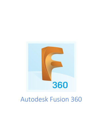
Autodesk Fusion 360 training5. Design HistoryFusion 360 can work with or without recording design history. Design history refers to the operationsyou perform on the design to create and modify geometry. Operations are recoded in the timeline at thebottom of the interface.When using parametric modeling, the design history is captured in the timeline at the bottom of theinterface. Operations are captured in the order they are performed in. History is captured for commandsin the Model and Patch workspaces. You edit the operations in the timeline to make changes to yourdesign.When using direct modeling, design history is not captured. The same commands are used from thetoolbar but there is no timeline. You use commands like Press Pull or Move to move faces and changeyour design.So, why use one over the other? Using history allows you to make precise predictable edits to one ormany components and allow the model to rebuild reliably. History is also useful if you plan to go switchbetween the model and sculpt workspaces. This allows you to create your outer shape, then createmodel operations (shell, split, hole, etc.) then go back and change your shape. If history is enabled, themodel operations will recalculate to fit the new shape.With direct modeling (history is off), you change geometry by moving faces. There are no operations toedit and therefore, no relationships between features in the design. Direct modeling works well forquick concept design or when working the imported data.You can control the default behavior for new designs using preferences or you can turn design historyon/off in the browser after a model is created.12
Autodesk Fusion 360 training6. Autodesk A360Fusion 360 uses Autodesk A360 to manage data and collaborate with teams. When you access yourdesigns in Fusion, you are actually using A360 under the hood. You can also access your data in a webbrowser using A360. A360 provides access and management of the versions of your designs. You canalso upload other supporting design documentation. A360 lets you manage who can access your designdata. All these tools within A360 make it easy to collaborate with team members.Get Started: To get started with Fusion 360, we will log in, create a project, and save a design to theproject.Step 2 – Log in to Fusion1. Launch Fusion 360.2. Use your Autodesk ID to log in to Fusion.If you do not have an Autodesk ID, you can createan account for free.Step 3 – Open the Data Panel1. Clickto display the Data Panel.2. The data panel slides open on the left.13
Autodesk Fusion 360 trainingStep 4 – Create a new project1. Clickto go to Autodesk A360 inyour Internet browser.2. Move the mouse overthen clickto begin creating anew project.3. Enter Fusion Training in the Name field.4. Enter email address in the ProjectContributors field to invite people to thisproject.14
Autodesk Fusion 360 training7. Hot KeysCommandUndoRedoCopyPasteCutWindowsCtrl ZCtrl YCtrl CCtrl VCtrl XMacCommand ZCommand YCommand CCommand VCommand XSculpt Workspace SelectionGrow selectionShrink selectionLoop selectionLoop grow selectionRing selectionRing grow selectionRing shrink selectionPrevious UNext UWindowsShift Up arrowShift Down arrowAlt PAlt OAlt LAlt KAlt JAlt Left arrowAlt Right arrowPrevious VAlt Down arrowNext VRange selectionInvert selectionToggle box modeToggle control frame modeToggle smooth modeSelect edge ringSelect face ringAlt Up arrowAlt MAlt NCtrl 1Ctrl 2Ctrl 3Double-click an edgeSelect two faces then doubleclicka third faceMacShift Up arrowShift Down arrowControl PControl OControl LControl KControl JControl Command Left arrowControl Command RightarrowControl Command DownarrowControl Command Up arrowCommand MCommand NCtrl 1Ctrl 2Ctrl 3Double-click an edgeSelect two faces then doubleclicka third faceEdit Form CommandAdd geometryAdd geometry and keep creasesWindowsAlt DragAlt Ctrl DragMacOption DragOption Command Drag15
Autodesk Fusion 360 trainingSketchingOverviewMany features that you create in Fusion 360 start with a 2D sketch. In order to create intelligent andpredictable designs, a good understanding of how to create sketches and how to apply dimensions andgeometric constraints. Fusion does support 3D sketches although, in this module we will cover basicsketching tools to create and edit a 2D sketch.Learning ObjectivesIn this section you will learn how to: Create a 2D sketch Create geometry in a sketch Use constraints to position geometry Use dimensions to set the size of geometryA Fusion design can contain multiples sketches. The sketch is an object that contains the geometry todefine profiles. Your sketches are listed in the browser. Sketches are also listed in the timeline inparametric designs.Sketches must be created on a plane. You can use the origin planes, construction planes, or a flat modelface to define a sketch.16
Autodesk Fusion 360 training8. Create SketchIn this exercise, you create a new Fusion design then create a new sketch in the design.Step 1 – Create a new design1. Launch Fusion 360.2. Start a new design.This creates a new design where you will creategeometry.Step 2 – Create a new sketch1. Select Sketch Create Sketch.Step 3 – Select the sketch plane1. You are now prompted to select a “plane”to sketch on.2. Select the “Front” (XY) plane.You can create sketches on one of the 3 defaultplanes, on a custom construction plane or on anexisting model face. More on this later.Sketches contain vector data. They are made of lines, circles, arcs and other curves. They are not artisticsketches or renderings.There are many commands available to create and edit sketch geometry.Basics: This exercise uses a few sketch commands to get you comfortable. We will delete the geometrylater.17
Autodesk Fusion 360 trainingStep 1 – Create a circle1. Select Sketch Circle Center DiameterCircle.2. Select anywhere in the screen to definethe center point.3. Move the mouse out until you have a sizeyou like.4. Click again to complete the command.Sketches usually consist of many types of“primitive” geometry added together.Step 2 – Create a rectangle1. Select Sketch Rectangle 2-PointRectangle.2. Select anywhere in the screen to start therectangle.3. Move the mouse out until you have thesize you want.4. Click again to complete the command.There are different ways to create circles andrectangles. Experiment with some of the otheroptions in the menu. See more here:Step 3 – Create a slot1. Select Sketch Slot Center to CenterSlot.2. Select anywhere in the screen to start theslot.3. Move out until you have a length you likethen click to establish the slot length.4. Now move out to define the width of theslot.5. Click again to complete the command.You will notice the various symbols that are beingcreated on the geometry. These are “constraints.”They control the relationships between the entitiesin the sketch.18
Autodesk Fusion 360 trainingStep 4 – Constrain the slot1. Select Sketch Constraints.2. Select one of the straight lines in the slot.3. Select Horizontal/Vertical.The Horizontal/Vertical constraint sets thegeometry to whichever is closer: horizontal orvertical.By adding a horizontal relationship to the slot wehave “fixed” its movement. Try dragging on someof the points to see the behavior.Step 5 – Dimension the width of the slot1. Select Sketch Sketch Dimension.2. Select one of the horizontals lines.3. Move the cursor out and click to place thedimension.4. Enter a value for the dimension.Typically we place dimensions after placinggeometry.This dimension now controls the length of the slot.You can double click it to change the value.Step 6 – Dimension the radius of the slot1. Now select the right arc (the dimensioncommand should still be active).2. Place the dimension.3. Press Esc to end the command.Notice that you cannot place a second dimension onthe left arc. This is because it would conflict with theother constraints we have created.19
Autodesk Fusion 360 trainingStep 7 – Sketch a profile1. Select Sketch Line.2. Draw the following shape by clicking in thisorder.3. Make sure on the last line you “connect” it tothe start point.If you finish it correctly you will see that the shape isshaded in. Notice that some constraints werecreated for you if you picked it right.Step 8 – Constrain the profile1. Select Sketch Constraints.2. Select these two lines.3. Select Perpendicular.Feel free to experiment with other constraintsbetween the lines.Step 9 – Constrain the profile1. Select Sketch Constraints.2. Select these two lines.3. Select Equal.You see how you can create more intelligence in themodels with relationshipsStep 10 – Dimension the profile1. Select Sketch Sketch Dimension.2. Place a dimension on the vertical line.3. Enter 100 mm for the value and note thename of the dimension, d3 in this case.4. Place a dimension on the top horizontal line.5. Enter d3 50 for the value.6. Now change the value of the verticaldimension and see the horizontal update.There is another method to make relationships. Tomodify these relationships you can go to:Modify Change Parameters20
Autodesk Fusion 360 trainingStep 11 – Delete the sketch profiles1. Zoom out to see everything.2. Select everything in the sketch by dragging aselection box.3. Press Delete.You should now have an empty sketch to start thenext part of the lesson.21
Autodesk Fusion 360 trainingOverviewMany features that you create in Fusion 360 start with a 2D sketch. In order to create intelligent andpredictable designs, a good understanding of how to create sketches and how to apply dimensions andgeometric constraints. Fusion does support 3D sketches although, in this module we will help you tonurture sketching tools to create and edit a 2D sketch.9. Base SketchNow we will begin to create some real sketch geometry that will be used to create 3D geometry.Step 1 – Sketch a circle1. Select Sketch Circle Center DiameterCircle.2. Select the origin (center point of the grid).3. Drag out a circle about 30 mm inDiameter. We will add the specific sizelater.Step 2 – Sketch another circle1. Select Sketch Circle Center DiameterCircle.2. Create another circle in roughly thisposition.Don’t worry about a specific size or position nowwe will fix that later.22
Autodesk Fusion 360 trainingStep 3 – Create lines1. Select Sketch Line.2. Click on the left circle to start the line.3. Hold Shift then click again where shown tomake the first line. Holding shift locks theline tangent to the circle.4. Click once more on the right circle at theposition where the line is tangent to thecircle.5. Press Esc to end the command.Step 4 – Fillet the lines1. Select Sketch Fillet.2. Select the intersection of the two lines.3. Type 10 mm into the input box.4. Press Enter.When you create a fillet “tangent” relations areadded to the sketch.Step 5 – Complete the profile1. Select Sketch Line.2. Select the left circle (2) as shown.3. Hold Shift then click near the number (3)as shown.4. Hold down the left button on the endpoint of the line and drag to create an arc.5. Click (5).6. Click on the right circle (6).If you make a mistake just feel free to delete thelines and try again.23
Autodesk Fusion 360 trainingRelationships: Now we will see how to create dimensions and constraints for our sketch.Step 1 – Display the Constraints dialog box1. Select Sketch Constraints.This brings up the dialog box where you can createrelationships between sketch entities. Constraintswill determine how your sketch behaves. Once arelationship like tangent or perpendicular isapplied then it is persistent as you continue tomodify the sketch.Step 2 – Add tangent constraints1. Select the Tangent constraint.2. Apply tangent constraints at the locationsshown if they do not already exist.3. Make sure you have 8 tangent symbols onyour sketch.You may have noticed that there are already someof these created as you were sketching. Manycommands in Fusion 360 allow you to createrelationships “on-the-fly.” As you become morefamiliar with the tool this will make more sense.Step 3 – Dimension the circle1. Close the constraints dialog box.2. Select Sketch Sketch Dimension.3. Select the left circle.4. Click again to place the dimension.5. Change the value to 31mm.6. Press Enter.This is how we size our sketch. It is very commonto draw things out in rough position then go backand add sizing information. Later we will showhow to add this at creation.24
Autodesk Fusion 360 trainingStep 4 – Dimension the profile1. Repeat the process for the right circle andtwo arcs.2. Change the values to match those shownhere.Once you have started the dimension command itstays active. You do not have to go to the menueach time to activate it.Step 5 – Add more dimensions1. Make sure the dimension command is stillactive.2. Select the center point of the left circle.3. Select the center point of the lower arc.4. Place the dimension to the left center ofthe two points.5. Don’t change the value yet (Don’t worry ifyour value is different).Depending on where you place the dimension youget different results. You can make horizontal,vertical and shortest distance dimensions bywhere you drag the dimension when you areplacing it. Once the dimension is placed you can’tchange it. If you make a mistake delete thedimension and start again.25
Autodesk Fusion 360 trainingStep 6 – Add more dimensions1. Select the center point of the left circle.2. Select the center point of the lower arc.3. This time place the dimension to the lowercenter position to create a horizontaldimension.4. Place the dimension but don’t edit thevalues.Sometimes it is better to place your dimensionsfirst before changing the values. When somegeometry doesn’t have any relationships yet it canbehave in unexpected ways.Step 7 – Add more dimensions1. Repeat the process for the upper arc andthe left circle.2. Create two dimensions between the leftcircle and the center point of the rightcircle.Your sketch should look like this although you willhave different values for the dimensions. We willchange the values in the next step.26
Autodesk Fusion 360 trainingStep 8 – Set the dimension values1. Double click a dimension to change itsvalue.2. Change the values of the dimensions tomatch those shown.3. Follow the order of the numberedballoons for the best results.What is happening under the hood is the softwareis “solving” all the relationships at once. It ispossible that you will try to enter a dimension thatconflicts with the other values. As you becomemore familiar with the behavior you will get asense of the best order to makes changes for thedesired result.The end result of a sketch is often to create a 3D feature. Fusion automatically discovers closed profilesthat can be used in 3D features.Creating Geometry: Next we will use this sketch to create 3D geometry.Step 1 – Leav
Autodesk Fusion 360 training 10 4. Workspaces Fusion 360 uses workspaces control the commands that are available and the type of data that is created. There are multiple workspaces available depending on the work you plan to perform. Sculpt: create organic shapes by manipulating faces, edges, and vertices.