Transcription
Safe Operation and MaintenanceofCircuit Breakers and Switchgear
THIS BOOK WAS DEVELOPED BY IDC TECHNOLOGIESWHO ARE WE?IDC Technologies is internationally acknowledged as the premier provider of practical, technical trainingfor engineers and technicians.We specialize in the fields of electrical systems, industrial data communications, telecommunications,automation and control, mechanical engineering, chemical and civil engineering, and are continuallyadding to our portfolio of over 60 different workshops. Our instructors are highly respected in their fieldsof expertise and in the last ten years have trained over 200,000 engineers, scientists and technicians.With offices conveniently located worldwide, IDC Technologies has an enthusiastic team of professionalengineers, technicians and support staff who are committed to providing the highest level of training andconsultancy.TECHNICAL WORKSHOPSTRAINING THAT WORKSWe deliver engineering and technology training that will maximize your business goals. In today’scompetitive environment, you require training that will help you and your organization to achieve its goalsand produce a large return on investment. With our ‘training that works’ objective you and yourorganization will: Get job-related skills that you need to achieve your business goals Improve the operation and design of your equipment and plant Improve your troubleshooting abilities Sharpen your competitive edge Boost morale and retain valuable staff Save time and moneyEXPERT INSTRUCTORSWe search the world for good quality instructors who have three outstanding attributes:1. Expert knowledge and experience – of the course topic2. Superb training abilities – to ensure the know-how is transferred effectively and quickly to you ina practical, hands-on way3. Listening skills – they listen carefully to the needs of the participants and want to ensure that youbenefit from the experience.Each and every instructor is evaluated by the delegates and we assess the presentation after every class toensure that the instructor stays on track in presenting outstanding courses.HANDS-ON APPROACH TO TRAININGAll IDC Technologies workshops include practical, hands-on sessions where the delegates are given theopportunity to apply in practice the theory they have learnt.REFERENCE MATERIALSA fully illustrated workshop book with hundreds of pages of tables, charts, figures and handy hints, plusconsiderable reference material is provided FREE of charge to each delegate.ACCREDITATION AND CONTINUING EDUCATIONSatisfactory completion of all IDC workshops satisfies the requirements of the International Associationfor Continuing Education and Training for the award of 1.4 Continuing Education Units.IDC workshops also satisfy criteria for Continuing Professional Development according to therequirements of the Institution of Electrical Engineers and Institution of Measurement and Control in theUK, Institution of Engineers in Australia, Institution of Engineers New Zealand, and others.
CERTIFICATE OF ATTENDANCEEach delegate receives a Certificate of Attendance documenting their experience.100% MONEY BACK GUARANTEEIDC Technologies’ engineers have put considerable time and experience into ensuring that you gainmaximum value from each workshop. If by lunchtime on the first day you decide that the workshop is notappropriate for your requirements, please let us know so that we can arrange a 100% refund of your fee.ONSITE WORKSHOPSAll IDC Technologies Training Workshops are available on an on-site basis, presented at the venue ofyour choice, saving delegates travel time and expenses, thus providing your company with even greatersavings.OFFICE LOCATIONSAUSTRALIA CANADA INDIA IRELAND MALAYSIA NEW ZEALAND POLAND SINGAPORE SOUTH AFRICA UNITED KINGDOM UNITED STATESidc@idc-online.comwww.idc-online.comVisit our website for FREE Pocket GuidesIDC Technologies produce a set of 6 Pocket Guides used bythousands of engineers and technicians worldwide.Vol. 1 – ELECTRONICSVol. 4 – INSTRUMENTATIONVol. 2 – ELECTRICALVol. 5 – FORMULAE & CONVERSIONSVol. 3 – COMMUNICATIONS Vol. 6 – INDUSTRIAL AUTOMATIONTo download a FREE copy of these internationally best selling pocket guides go to:www.idc-online.com/downloads/
PresentsSafe Operation and MaintenanceofCircuit Breakers and SwitchgearRevision 6.1Website: www.idc-online.comE-mail: idc@idc-online.com
IDC Technologies Pty LtdPO Box 1093, West Perth, Western Australia 6872Offices in Australia, New Zealand, Singapore, United Kingdom, Ireland, Malaysia, Poland, United States ofAmerica, Canada, South Africa and IndiaCopyright IDC Technologies 2008. All rights reserved.First published 2008.All rights to this publication, associated software and workshop are reserved. No part of this publicationmay be reproduced, stored in a retrieval system or transmitted in any form or by any means electronic,mechanical, photocopying, recording or otherwise without the prior written permission of the publisher. Allenquiries should be made to the publisher at the address above.ISBN: 978-1-921007-37-8DisclaimerWhilst all reasonable care has been taken to ensure that the descriptions, opinions, programs, listings,software and diagrams are accurate and workable, IDC Technologies do not accept any legal responsibilityor liability to any person, organization or other entity for any direct loss, consequential loss or damage,however caused, that may be suffered as a result of the use of this publication or the associated workshopand software.In case of any uncertainty, we recommend that you contact IDC Technologies for clarification or assistance.TrademarksAll logos and trademarks belong to, and are copyrighted to, their companies respectively.AcknowledgementsIDC Technologies expresses its sincere thanks to all those engineers and technicians on our trainingworkshops who freely made available their expertise in preparing this manual.
Contents12345Switchgear in a Network Context11.11.21.31.41.51.6222358Single line diagramsActive and passive componentsCircuit breaker utilizationForms of medium voltage switchgearBasic circuit breaker designAuto reclosingSwitchgear in an Historic Perspective132.12.22.32.42.52.6131819232325Plain break oil circuit breakersSmall oil volume circuit breakersAir blast circuit breakersOperating mechanismsSF6 and vacuum circuit breakersPuffer type SF6 circuit breakersSwitchgear Rating and 3.123.133.142930313334343536363637384044Standards and factors affecting circuit breaker selectionRated voltage UrRated insulation levelRated short time withstand current (Ik)Rated peak withstand current (Ip)Symmetrical and asymmetrical ratingRated supply voltage of closing or opening devices (Ua)Rated supply frequency of closing or opening devicesStored energy operationLocking and interlocking devicesEnclosure degrees of protectionGas leakage ratesTesting for internal faultSwitchgear ancillaries, measurement CTs, VTsProtection474.14.24.3475557Protection systemsCable terminationsSubstation and switch room layout and designSafety Policies615.15.26162Principles of safety rulesOperative training
5.35.45.55.65.75.85.95.105.115.126Asset Management in a Switchgear Context6.16.26.36.46.56.66.76.878Personnel levels of competencySafety documentationWork on live systems or close to live systemsSwitching schedulesSpecial precautions when working on switchgearPolicies for operational and safety locking, safety noticesand remote operationSwitchgear operation case studiesSubstation inspection checklistPersonal protective equipment (PPE)Fire protection in substationsOverviewInsulation deteriorationSwitchgear diagnostic techniquesSubstation battery condition and monitoringSwitchgear maintenance proceduresProblems that may be found during switchgearmaintenanceDefect managementExamples of switchgear aintenance of Circuit 125126128The importance of adequate maintenanceLVCB on-site maintenanceMaintenance of molded case circuit breakersMaintenance of low voltage circuit breakersMaintenance of medium voltage circuit breakersElectrical testsSf6 breakersSummaryLow Voltage 30130131131132135136139141142IntroductionAir circuit breakersMolded case circuit breakersArc chutesThermal tripping methodsHydraulic tripping methodsPrecautionsApplications and selective co-ordinationEffect of point-on-wave occurrence- cascade systemsIES 4 polarized releaseTime-current response curve
8.128.13ABCD143143Need for Protection145A.1A.2A.3145145146Need for protective apparatusBasic requirements of protectionSummaryFaults, Types & Effects149B.1B.2149151The development of simple distribution systemsFaults - types and their effectsSimple Calculation of Short Circuit ionRevision of basic formulaeCalculation of short circuit MVAUseful formulaeCable informationCase Study-Design of a Typical HV Switchboard ETypical LV distribution systemsSummaryPreambleStandardizationInputsDesign step-1: Basic equipment configurationDesign step-2: Ratings of equipment and devicesDesign step-3: Control interfacingDesign step-4: Board dimensionsDesign step-5: Space requirementsDesign step-6: Planning for other facilitiesDesign ase Studies of Circuit Breaker Related Failures181E.1E.2181182Case study 1: circuit breaker failureCase study 2: turbine outageQuestions185Answers199
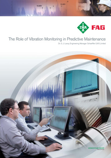
1Switchgear in a Network Context1.1Single line diagramsFigure 1.1 shows a typical example of a high voltage distribution network, represented as a singleline diagram, complete with transformer infeeds, cable and overhead circuits, distributionsubstations, circuit breakers and other network switchgear. The term 'Single line diagram' simplymeans that the three phase nature of the circuits and components is ignored.1.2Active and passive componentsNetwork components may be divided into two broad categories, those that are continuously in usewhenever electricity is being supplied, called the ACTIVE components and those called upon tofunction only when required to do so, the PASSIVE components.ACTIVE components comprise transformers, cables, overhead lines and metering equipment andmay be considered the main revenue earning elements. PASSIVE components compose mainlyswitchgear in its various forms, together with switchgear's ancillaries, current and voltagetransformers and protection relays. These components perform no revenue earning function andmay be considered as an added cost, to be minimized wherever possible.
2 Safe Operation and Maintenance of Circuit Breakers SwitchgearFigure 1.1Typical network as a single line diagram1.3Circuit breaker utilizationIn an ideal network having perfect reliability and no maintenance or repair requirement, there is noneed to break the electric circuits; however, this is impossible; therefore switchgear has to beinstalled. However, we should be careful not to install more switchgear than is absolutely requiredand the switchgear that is installed should have no more functionality than is necessary.The two most common forms of medium voltage switchgear are automatic circuit breakers andnon-automatic, load breaking, fault making switches. The main function of a circuit breaker is toautomatically interrupt fault current, although an important secondary function is to close onto afault and thereby make fault current. This function may be required during for example, faultlocation. The automatic disconnection of faults by circuit breakers allows the remainder of thenetwork to continue in operation, after the faulty branch has been disconnected. Without thisfeature, network operation would be 'all or nothing'.
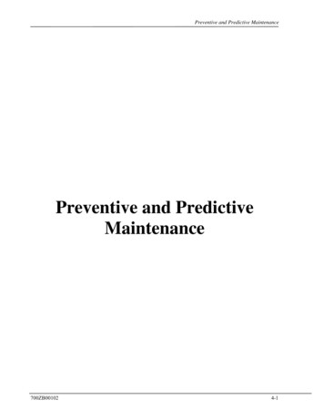
Switchgear in a Network Context3In theory all the switchgear shown in Figure 1.1 could be implemented by circuit breakers, but thischoice would be very expensive and result in an excessive maintenance burden. In practice, circuitbreakers are normally located only at the beginning of the cable, overhead line or mixed circuit,where they serve to disconnect faults either phase to phase or phase to neutral/earth (or both).1.4Forms of medium voltage switchgearHistorically, circuit breakers were also utilized at each distribution substation, to control andprotect the transformer, although fuse switches may nowadays implement this function. Mediumvoltage fuses are available up to a current rating equivalent to a three phase rating of approximately1.5 MVA and offer a cost-effective means of transformer protection. Generally they are combinedwith a three phase disconnector and a 'trip all phases' device, so that if one fuse fails, thedisconnector trips and the supply to the transformer are fully disconnected. If this device were notfitted, the transformer may be subjected to 'single phasing' and a corresponding low LV sidevoltage (see Figure 1.2).Figure 1.2Fuse switch in cross sectionThe remainder of the switchgear on the system shown in Figure 1.1 comprises non-automatic, loadbreaking, fault making switches. The main function of this form of medium voltage switchgear isto subdivide the circuit part of the network into smaller, more manageable sections, so that in theevent of a fault, supply may be restored to a greater number of distribution substations, by manualswitching. During switching operations, the precise location of, for example, a cable fault may notbe precisely known and there is a possibility that a non-automatic switch may be closed onto afault, hence the need to have a 'fault making' capability. An important secondary function of bothcircuit breakers and non-automatic switchgear is to allow safe access to the circuit conductors,thereby permitting the application of various cable fault location techniques.
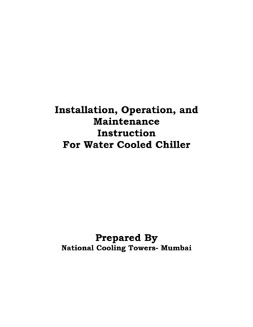
4 Safe Operation and Maintenance of Circuit Breakers SwitchgearNon-automatic load breaking, fault making switchgear may be implemented as separate switches,or linked together to form a switchboard, or they may be combined with a fuse switch or circuitbreaker into a 'Ring Main Unit' (RMU).Ring Main Units are commonly combined with transformers and LV switchgear to form what hasbecome known as UNIT or COMPACT substations, delivered as completed products from thefactory, needing only to be cabled up and commissioned.Considering Figure 1.1 further, the circuit shown heavy line is typical of a supply circuit in anurban area. Each end of the circuit connects to a circuit breaker at Primary substations A and B,where supply is obtained from a higher voltage system. At an intermediate point, (marked C) asystem 'open point' is implemented by non-automatic switchgear and the circuit is broken into tworadial feeders. The extent of each radial may be varied by manual switching and further systemflexibility is provided by additional 'open points' connecting to other circuits. It should however beappreciated that whilst the switchgear on network provides greater system flexibility and improvesnetwork reliability, it does so at considerable cost, including the cost of faults on the networkswitchgear itself and the cost of its periodic maintenance. In the typical network of Figure 1.1,more that 80% of all switching operations are likely to be caused by repair or maintenancerequirements on other network switchgear.Where circuits have many connected substations and hence a heavy load, it may be beneficial froma reliability standpoint to install a second circuit breaker at an intermediate point on the network,grading in its protection with the circuit breaker at the Primary substation. This arrangement offersautomatic protection of supplies in the first half of the feeder, when faults occur in the second half.For example, in Figure 1.4, faults occurring beyond the location of the network circuit breaker at Xwill not cause loss of supply at substations between X and Y, if the protection settings of X areproperly graded. However, there is the disadvantage that, as the protection is time graded, all faultson the circuit will take a longer time to clear, due to the need to set circuit breaker Y to a longersetting.Figure 1.3Ring main Unit - Schneider RN2C
Switchgear in a Network Context5Figure 1.4Supplementary circuit breaker1.5Basic circuit breaker designAlthough a circuit breaker may carry out various secondary functions, its primary purpose is tointerrupt fault current automatically. The main problem of arc extinction and hence currentinterruption may be stated as ensuring that the dielectric strength across the contact gap exceeds theimpressed voltage across the gap at time of current zero. To interrupt a circuit where the current isa few hundred amperes and the power factor is close to unity is not a problem, but it becomes aproblem where the current is thousands of amperes and the power factor is low.
6 Safe Operation and Maintenance of Circuit Breakers SwitchgearConsider the circuit shown in Figure 1.5.Figure 1.5Local and distant faultsFor the distant fault shown at A, circuit impedance, mainly resistance, acts to limit the fault currentand bring the power factor to a value close to unity. As the voltage and current are almost in phase,the voltage across the open contacts of the circuit breaker is low at the time of current zero; hencethe probability of arc extinction is high. This is illustrated in Figure 1.6.Figure 1.6Phase relationship for a distant faultIn the case of fault B, close to the circuit breaker terminals, generator reactance predominates andthe power factor is low, perhaps 0.15. Thus at the time of current zero, when the circuit breaker actsto interrupt the fault, the voltage across the opening contacts is high. The high voltage across theopen contacts at time of natural current zero makes interruption more difficult and there is aprobability of the arc re-striking. This is shown in Figure 1.7.Figure 1.7Phase relationship for a close faultAs the contacts continue to separate, the arc length increases and the dielectric strength of the gapincreases, according to the particular design of the circuit breaker. To limit the fault duration andhence damage, arc extinction and fault current interruption should occur at the earliest possiblecurrent zero, of which there are two in each current cycle. In practice, this ideal is not alwaysachieved and depending upon the type of circuit breaker, the magnitude of the fault current and thepower factor, several current cycles may occur before interruption is achieved. It is also highlydesirable that fault current is not interrupted at any time other than a natural current zero; if it is, the
Switchgear in a Network Context7effect is called 'current chopping'. This effect is a practically instantaneous collapse of current thatcan lead to severe over-voltages and system damage. It is an acute problem when the circuitbreaker has to deal with very low current values, for example transformer magnetizing current orcapacitive line charging current.During arcing, the voltage across the open contacts is known as the arc voltage and is relatively lowwith heavy current, short length arcs. In Figure 1.8 it is shown as Va and at the instant of currentzero it rises rapidly to the value of the peak value of the re-striking voltage transient. This voltageoscillates around the 50 Hz recovery voltage at a frequency that depends upon the resonantfrequency of the system, determined by circuit R and X.Figure 1.8Variation of arc voltage with timeThis oscillating voltage merges by damping into the recovery voltage at normal frequency, but itsvalue is important in circuit interruption. This value may be affected by the value of the peakvoltage at 50 Hz as shown in Figure 1.8 but it is also affected by the nature of the fault. Forexample, in Figure 1.9 the blue phase has cleared whilst the remaining two phases are stillconnected via the circuit breaker arcs.Figure 1.9Effects of different clearance times on three-phase faultIn the situation shown in Figure 1.9, where the neutral, or the fault or both are not earthed, theinstantaneous voltage across the first circuit pole to clear will be 50% greater than the line toneutral peak. Thus the instantaneous value of the re-striking voltage may reach 2 x 1.5 x phase toneutral volts. In practice, two or more natural frequencies may be present across the open contacts,resulting in a composite frequency as shown in Figure 1.10.
8 Safe Operation and Maintenance of Circuit Breakers SwitchgearFigure 1.10RRRVThe rate of rise of recovery voltage (also known as RRRV and measured in volts per microsecond)is a factor that greatly affects circuit breaker performance; its value may be obtained by drawing astraight line through zero and tangential to the steepest part of the curve.Some forms of circuit breaker are particularly sensitive to re-striking voltage, notably air blastcircuit breakers. For this reason, what is described as resistance switching has been resorted to inaxial blast designs. Resistance damps the oscillation of the arc voltage and is obtained by switchingresistance in during the arc interruption process. Early designs of vacuum circuit breaker wereprone to current chopping, but this effect has been eliminated with improved contact designs.1.6Auto reclosingIn networks comprising substantial lengths of overhead line, many of the faults that occur will betransient in nature. These are caused for example by wind blown debris bridging conductors,insulator flashover, etc. The reliability of the supply may be considerably improved by arrangingfor the controlling circuit breaker (at R in Figure 1.11) to re-close automatically after a fault occurs.This ensures that for transient faults, the restoration time is measured in seconds, rather than thehours it might take for an engineer to travel to the substation and re-close the circuit breakermanually.
Switchgear in a Network Context9Figure 1.11Re-closed overhead line networkOn overhead line networks, most transformers and spur lines are protected by medium voltageexpulsion type fuses to BS 2692 (no IEC equivalent) and it will be necessary for the protection/reclose relay of the circuit breaker controlling the circuit to grade with these fuses. This ensures thatwhere a fault on a connected transformer or spur line is permanent, the circuit breaker will close forlong enough to allow the fuse to blow, before the circuit is re-energized. Fitting the circuit breakerwith a timing mechanism to provide, for example, two instantaneous trips and two delayed tripsfulfils these requirements. The timing sequence adopted varies according to local conditions, butFigure 1.12 shows a typical arrangement.Figure 1.12Typical auto re-close sequenceThe timing sequence is described as follows. At the instant when the fault occurs, the circuitbreaker trips immediately and remains open for 1 second. This period is intended to allow for anyionized gases to clear. The circuit breaker then attempts a first re-closure. If the fault is still present,the circuit breaker trips again and remains open for a further 1 second. The second re-closure thenoccurs, but this time, if the fault is still present, tripping is delayed. This is because the systemassumes that the fault lies beyond a fuse or fuses and it therefore allows sufficient time for thefuse(s) to rupture. If fault current still persists, a third re-closure is attempted, again with delayedtripping.
10 Safe Operation and Maintenance of Circuit Breakers SwitchgearAfter this, the system assumes that the fault is permanent and 'locks out'. It must be re-set eithermanually or over a telecontrol system. If the fault is cleared at any time during the sequence, thesystem re-sets itself automatically, ready for the next fault and re-closure sequence.Figure 1.13Pole mounted auto-recloser (at A)The satisfactory operation of a re-closed circuit breaker in association with fuses depends upon thedegree of co-ordination obtained, requiring that the time/current characteristic of the re-closedcircuit breaker be graded with those of the fuses to give optimum discrimination. The first tripsmust be short enough that the fuses are not degraded, whilst the second and third must be longenough to allow the fuses to operate.It should be appreciated that whilst re-closing is not a problem for vacuum and SF6 circuit breakers,oil circuit breakers have a very limited re-closing capability, depending upon the fault level.Normally, the number of re-closures that may be performed by an oil circuit breaker isprogrammed into the controlling auto re-close relay and when that limit is reached, further autoreclosing is prevented until the circuit breaker has been maintained. The advice of manufacturersshould be obtained when deciding upon the number of re-closures a particular design of oil circuitbreaker may perform.A disadvantage of re-closed circuit breakers is that, where the controlled network comprises bothoverhead line and cable, the supply to cable supplied customers will be adversely affected by reclosing operations caused by faults on the overhead network. In practice, this means that thecustomers on the cable network will experience momentary losses of supply, which they would notexperience if the network were not re-closed. In addition, in the case of cable and plant faults, theadditional fault closures may well cause additional damage. This effect can be reduced by goodnetwork design, or alternatively a pole-mounted re-closer may be used, as shown in Figure 1.13. Inthe network shown in Figure 1.13, the cabled part of the network is controlled by a circuit breakernot fitted with auto-reclose, whilst the overhead line part of the network is controlled by the pole
Switchgear in a Network Context 11mounted auto recloser at point A. Originally, oil filled pole-mounted reclosers were used for thispurpose, but vacuum and SF6 designs are now available.Figure 1.14 shows a sectional view of a typical pole mounted, oil filled auto recloser, together witha basic circuit diagram. This particular design, comprising all three phases in a common tank, wasmanufactured in large quantities and remains in service, although SF6 and vacuum designs havesuperseded it. It features two instantaneous trips plus two delayed trips, the latter controlled by oildashpots. Both overcurrent and earth fault protection are fitted; the latter can be switched out ifrequired.Figure 1.14Pole mounted, oil filled recloserThe energy to charge the spring mechanism of the recloser is derived from the circuit itself, so as toavoid the need for auxiliary low voltage supplies. Passage of fault current through the seriesovercurrent coils causes the recloser to OPEN and the trip sequence (normally two instantaneous,two delayed) to be performed automatically, proceeding to lock-out if appropriate. The energy tore-charge the spring mechanism is derived from a solenoid, operating through its own auxiliarycontacts that CLOSE when the main contacts are OPEN and OPEN when the main contacts areCLOSED. When the solenoid is energized, it pulls in its iron armature until almost at the end of thesolenoid stroke; the auxiliary contacts are caused to OPEN. The solenoid de-energizes and the ironarmature is released, until the auxiliary contacts again CLOSE. The OPEN and CLOSE action isrepeated approximately seven times, causing the spring mechanism to charge through a clutch andratchet device. Note that this device must be correctly installed as regards the source of supply; itwill not operate in the reverse configuration.As the spring mechanism charges, a rotating cam is moved to a position where, just after the lastcharging stroke, the spring is discharged, closing the recloser. In the event that the fault ispermanent, the recloser locks out and may then only be re-set manually, using a long insulated rod.Sequence timing for the two delayed operations is obtained by an oil dashpot, which for theinstantaneous operations is by passed by a piston valve. The position of the piston valve determineswhether the closure is immediate or delayed and is controlled by a sequence cam; by varying theposition of this cam, the number of immediate and delayed trips can be varied.Earth faults are detected by a core balance protection system, derived from ring type CTs andoperating a tripping coil through a rectifier. Earth fault type operation is always immediate, nodelayed tripping is allowed.
12 Safe Operation and Maintenance of Circuit Breakers SwitchgearAlthough pole mounted oil filled reclosers of this type can perform a very useful network function,they have a limited fault rating (typically 50 to 100 MVA) and also require frequent maintenance.These problems are reduced by more modern SF6 and vacuum types, which are usuallymicroprocessor controlled and powered by long life Lithium batteries.The type of recloser shown in Figure 1.15 is a great operational advance on the oil filled design thatwas described earlier. Maintenance requirements are low and the unit may be regarded as almostmaintenance free, at least so far as the user is concerned, being limited to simple replacement of theprimary battery at perhaps 5-year intervals. The vacuum interrupters will provide hundreds ofreclosers; eventually, replacement will be required but this is a return to factory operation. Afurther advantage is that the bushings are elastomeric and less readily damaged than porcelain,either during installation or in service.In these units the control system is normally sited in a lockable metal box close to ground level,remotely from the recloser proper and connected to it by a multicore (umbilical) cable. Because theprotection system is microprocessor controlled, any number of possible reclosure strategies may beimplemented, exactly as the operator req
5.12 Fire protection in substations 77 6 Asset Management in a Switchgear Context 79 6.1 Overview 79 6.2 Insulation deterioration 85 6.3 Switchgear diagnostic techniques 87 6.4 Substation battery condition and monitoring 95 6.5 Switchgear maintenance procedures 104 6.6 Problems that may be