Transcription
TUTORIALBPMN Modeler for Visio
Table of ContentsTable of ContentsDisclaimer . 3Building a Process Model . 4Build the Organization Chart . 5Create the Organization Page . 6Create the Organization Chart . 6Link the Organization Units . 7Open the Resources Page . 7Create a Role . 8Add the Resources . 8Adding Phone Number and E-mail to a Resource . 9Build the Process Hierarchy . 10Overview of Process Hierarchy . 10Create Top-Level Process Flow . 11Insert Top-Level Links . 11Break Down the Process Flow - Develop Job Description . 13Link the BPMN Shapes . 15Break Down the Process Flow - Initiate Recruitment . 15Break Down the Process Flow - Interview Candidates . 18Review Process Inputs and Outputs. 19Create the Materials Page . 19Add Materials to the Materials Page . 20Define Inter-Process Links . 21Define the Remaining Links . 22Create and Assign the Remaining Materials . 24Create a Flat Map . 26Assign Probabilities to Outputs of the Gateway Shape. 27Tutorial 2012 Interfacing Technologies CorporationBPMNTUT-0820121
Table of ContentsVerify Completed Process Map . 28Assign Process Properties . 30Assign Performers to BPMN Shapes . 31Make Properties Visible . 33Assign KPI’s to your processes . 35Displaying Properties in a Separate Text Box . 36Generate the Function Flow Page. 37Tutorial 2012 Interfacing Technologies CorporationBPMNTUT-0820122
DisclaimerDisclaimerCopyright (c) 2012 Interfacing Technologies Corporation. All rights reserved.This document, as well as the software described in it, is furnished under license and may be used or copied only inaccordance with the terms of such license. The content of this document is furnished for informational use only, anddue to product development, this information is subject to change without notice, and should not be construed as acommitment by Interfacing Technologies Corporation. Interfacing Technologies Corporation assumes noresponsibility or liability for any errors or inaccuracies that may appear in this documentation. Except as permitted bysuch license, no part of this publication may be reproduced, stored in a retrieval system, or transmitted, in any form orby any means, electronic, mechanical, recording, or otherwise, without prior written permission of InterfacingTechnologies Corporation.The Interfacing Technologies logo and Enterprise Process Center logo are trademarks of Interfacing TechnologiesCorporation.Many of the designations used by manufacturers and sellers to distinguish their products are claimed as trademarks.Interfacing Technologies has made every effort to supply trademark information about manufacturers and theirproducts mentioned in this publication. For the most up to date list, please refer to the Enterprise Process CenterOnline Help.Tutorial 2012 Interfacing Technologies CorporationBPMNTUT-0820123
Building a Process ModelBuilding a Process ModelThe following tutorial will take you through the basic steps in creating a simple process model using theInterfacing BPMN Modeler. The purpose of the tutorial is to illustrate some key modeling concepts andalso to show you how to properly construct a process model.The estimated time to complete the tutorial is 1½ to 2 hours. For the best results, try to complete thetutorial in a single session.Model overviewWe will call our simplified model “Hire New Employees”, which describes the process of recruiting andhiring a new employee.Before the recruiting process can begin, the Human Resources department must verify that the jobdescription is properly updated. Once this has happened, the job is posted to employees within thecompany as well as to the general public. Candidates are selected from the pool of applicants, and theHuman Resources manager determines which candidate to hire after conducting job interviews.Open and name a new drawing1. From the Start menu, choose the option All programs Interfacing BPMN Modeler for Visio New BPMN Model. A drawing page entitled New Scenario opens. This is called the Scenariopage and is always the first page of a model. If you are prompted, you will need to EnableMacros.2. Right-click the blank page and select the option Properties. This opens the Custom PropertyEditor for the Scenario page.3. The Scenario Name field is used to enter the name of the enterprise or top-level department youwish to model. Enter the name “Human Resources”.4. The Description field is used to briefly explain the purpose of your model. Enter the text“Modelsthe processing of hiring a new employee”.5. Click OK.Save the drawing1. From the Visio toolbar, select File Save.2. The first time you save a drawing, the Save As window appears. Choose a location for the file.3. Enter the desired file name.4. Make sure that Drawing (*.vsd) is showing in the Save as type field. Select it from the dropdown if it is not displayed.5. Click Save.Tutorial 2012 Interfacing Technologies CorporationBPMNTUT-0820124
Build the Organization ChartA complete business process model, to be analyzed properly, requires both an organization chart and aprocess hierarchy. The organization chart describes the departments, the Roles (i.e. roles or assets), andthe resources that participate in the model. The process hierarchy is a sequence of linked activities thatrepresent the flow of work through the model.You can create a high-level map of a process without creating an organization chart. The InterfacingBPMN Modeler also lets you create your organization chart and add resources "on the fly" as youfill in process and activity details. For the purposes of this tutorial, we will begin by creating theorganization chart and resources.Build the Organization ChartFor the sake of simplicity, our organization consists of four units: a top-level Unit called "HumanResources", which represents the main department, and three sub-units called "Administration","Recruitment", and "Network Systems". In this part of the tutorial you will learn how to create theOrganization page, build an organization chart and define resources for the units in the organization.Tutorial 2012 Interfacing Technologies CorporationBPMNTUT-0820125
Build the Organization ChartCreate the Organization PageOn the Scenario page of our model:1. Right-click an empty area of the page.2. Select Create Organization Page. The page is created and named automatically. When thisprocedure ends, you will be on the new Organization page.Move between the Organization and Scenario pages1. Locate the navigation tabs at the bottom of the page, to the left of the horizontal scroll bar.2. Select the Scenario tab. This brings you to the Scenario page. You will see a rectangle namedOrganization, as well as a rectangle named Resources.3. Right-click the Organization rectangle.4. Select Go To Organization. You will return to the Organization page. (Double-clicking theOrganization rectangle will also bring you to the Organization page.)Create the Organization Chart1. On the Organization page, double-click the default top-level organization unit namedEnterprise.2. When the Custom Property Editor opens, replace Enterprise with "Human Resources" as thename of the organization. Click OK. This shape will represent the top-level department in ourmodel.3. Drag the FS organization shape from the Scenario Advanced stencil and drop it onto theOrganization page below and to the left of the Human Resources department. Call this unit“Administration”.4. Drop two other FS organization shapes onto the page and call them “Recruitment” and"Network Systems".Note: You can also open the Custom Property Editor if you right-click the shape andselect Properties.Tutorial 2012 Interfacing Technologies CorporationBPMNTUT-0820126
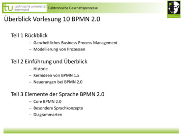
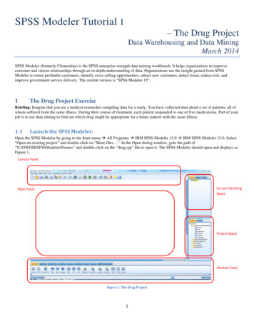
Build the Organization ChartLink the Organization Units1. Double-click the Administration organization to open the Custom Property Editor.2. Select the ellipsis button in the Parent field.3. Select Human Resources and click Assign Organization. The Human Resources is assignedas the parent of the Administration unit. Click OK.4. Repeat these steps to link the Recruitment and Network Systems organizations to the HumanResources organization.Your Organization page should now contain the following shapes:Open the Resources PageBefore we can assign individuals (resources) to perform tasks in our model, we must define the Roles (i.e.roles or assets) and individual resources by creating them on the Resources page.1. Select the Resources navigation tab at the bottom of the window.2. The Resources page will be displayed.Tutorial 2012 Interfacing Technologies CorporationBPMNTUT-0820127
Build the Organization ChartCreate a RoleIn business process models, most activities can be performed either by an individual resource or by aRole (i.e. roles or assets). Defining Roles allows you to have activities performed by resource poolswithout specifying which member of the pool will actually perform the activity. Each role represents oneresource pool.To create a resource pool, you must create a role, as well as the individual members of that role, andthen associate the members to an organization unit.Add the Roles1. From the Scenario Advanced stencil, drag the Role shape and drop it onto the Resourcespage.2. In the Custom Property Editor, enter “Servers Software” as the name of the role.3. Click OK.4. Repeat steps 1-3 to create two new roles named "HR Manager" and "AdministrativeAssistant".Add the ResourcesAfter you create the three new roles, you need to add resources and assign them to the existing types.1.From the Scenario Advanced stencil, drag the FS resource shape and drop it onto theResources page.2.In the Custom Property Editor, enter “HR System” as the name of the resource.3.Click the first ellipsis ( ) button next to the Org field to open the Organization Selection dialogbox. Select Network Systems from the list of available organizations. Click AssignOrganization.4.Click the Assign button next to the Roles field to open the Assign Roles dialog box.5.Select Servers Software from the list of available roles and click Assign. Users can selectmore than one role if necessary.6.Click OK. The HR System resource is linked to the Servers Software Role and the NetworkSystems organization.7.Repeat steps 1-6 using the table below to add new resources:Note: The Assigned Role and the Assigned Organization must be linked to the Resource Name.Resource NameAssigned RoleAssigned OrganizationJohn JohnsonHR ManagerRecruitmentBrenda BrownHR ManagerRecruitmentTom TompsonAdministrative AssistantAdministrationTutorial 2012 Interfacing Technologies CorporationBPMNTUT-0820128
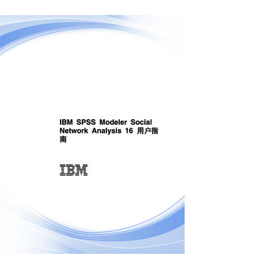
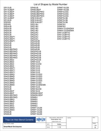
Build the Organization ChartYour Resources page should now resemble the following graphic. You may want to usethe auto-layout function (right-click and select Layout This Page), or drag the shapes manually, to adjustthe layout:Your Organization page should now contain all of the following shapes. You may want to use the autolayout function (right-click and select Layout This Page), or drag the shapes manually, to adjust thelayout:Adding Phone Number and E-mail to a ResourceYou can enter the contact information associated with your resources, such as the phone number and email address.This can be done in the Custom Property Editor window, next to the phone number and e-mail fields.Enter the phone number and email. Save your settings by selecting Apply and closing the window.Tutorial 2012 Interfacing Technologies CorporationBPMNTUT-0820129
Build the Process HierarchyBuild the Process HierarchyIn this section of the tutorial you will learn how to build a process hierarchy consisting of businessprocesses and BPMN shapes, as well as how to link them together to construct a logical process flow.You will also learn how to add certain properties to processes and BPMN shapes so that the flow of workis clear and easily communicated.Overview of Process HierarchyOur Hire New Employees process shows the steps involved in hiring a new employee. In a businessprocess model, each step (locate job description, verify accuracy, post internally/externally, receiveapplications, select candidates, interview candidates, offer position) is represented by a particular BPMNshape.In large models, it is usually more convenient to group BPMN shapes logically into a series of separatesub-processes. This way, the process can be displayed at a high level overview, or in detail.Tutorial 2012 Interfacing Technologies CorporationBPMNTUT-08201210
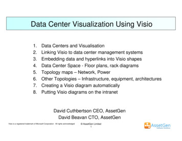
Build the Process HierarchyCreate Top-Level Process FlowOur Hiring Process contains three sub-processes called “Develop Job Description”, "Initiate Recruitment",and “Interview Candidates”.Create top-level shapes1. Go to the Scenario page.2. From the BPMN stencil, drag the Process shape onto the Scenario page.3. When the Custom Property Editor opens, enter “Hire New Employees” as the name of theprocess.4. Click OK. A separate page is created for each process, and a process shape called Hire New5. Employees will be added to the Scenario page.6. To see the new page created for this process, right-click Hire New Employees.7. Choose Go To Process. You will jump to a blank page entitled Hire New Employees. We will usethis page to lay out the rest of the process flow.8. Add three processes to the Hire New Employees page. Enter the names "Develop JobDescription", "Initiate Recruitment", and "Interview Candidates" respectively for these newprocesses.Your Hire New Employees page should now look like this:Moving Between Process Pages1. Right-click the Hire New Employees page and choose Go To Parent. This takes you to theParent page, which is the page that holds the Hire New Employees shape.2. Return to the Hire New Employees page by double-clicking the Hire New Employees shape.Insert Top-Level LinksFrom the Interfacing menu, select Interfacing Explorer. When the Interfacing Explorer window opens,note the process hierarchy, as shown below.Tutorial 2012 Interfacing Technologies CorporationBPMNTUT-08201211
Build the Process HierarchyLinks between processes are often called "Inter-Process Links", which must originate from a specific stepwithin the source process, and link to a specific step within the destination process. Since we have not yetbuilt the content contained without our sub- processes, for now we will simply link the process shapes atthe top-level.1. In the Interfacing Explorer, double-click Hire New Employees.2. From the BPMN stencil, drag the FS process link shape to the Hire New Employees page andattach the source (left) end of the link right away (without releasing the mouse) to the outputconnector on the Develop Job Description shape. Then release the mouse.3. The link’s Custom Property Editor appears. For now, we will not modify anything. Click OK to closethe window. We will add Materials later on in the tutorial.4. Attach the destination (right) end of the link to the input connector on the Initiate Recruitment process.5. Repeat steps 2 and 3 to link the Initiate Recruitment process to the Interview Candidates process.Tutorial 2012 Interfacing Technologies CorporationBPMNTUT-08201212
Build the Process HierarchyThe Hire New Employees page should now look roughly like this:Break Down the Process Flow - Develop Job DescriptionCompleting the process flow requires breaking down each process into a series of specific steps.First, we will consider the process Develop Job Description. Let’s say that we have decided to modelthree activities in this process: locating the job description, evaluating the job description and modifyingthe job description. These activities are represented by tasks.The process begins when Human Resources receives a request for a new employee from an outsidedepartment. This request becomes the trigger that initiates all subsequent activities. In a businessprocess model, the starting point is usually represented by a start event. The start event is used when it isnecessary to introduce new input that originates outside the model (from another department, in ourcase). Start events, in other words, represent incoming data, or occurrences, that trigger the flow of workwithin the process.In our model, we will create a start event named “Receive notification” which will provide the input thatsets all the other tasks in the model in motion. Consequently, a start event cannot accept incoming linksfrom another activity within the model.Here is how we proceed.1. On the Hire New Employees page, right-click the Develop Job Description process shape andchoose Go To Process. This brings you to a blank page entitled Develop JobDescription.2. From the BPMN stencil, drag the Start shape to the page.3. When the Custom Property Editor opens, type “Receive notification” as the name of the event.Click OK. The shape is added to the page.4. Right-click the shape and select Message to indicate the type of start event. The Message typeindicates that some kind of message is being exchanged. In this case, the message is a requestfor new employees, from an outside department.Tutorial 2012 Interfacing Technologies CorporationBPMNTUT-08201213
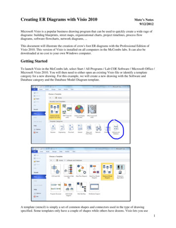
Build the Process HierarchyWhen it is necessary to represent an action that is being performed in a business process model, we usethe Task shape.1. From the BPMN stencil, drag the Task shape and drop it onto the page.2. When the Custom Property Editor opens, enter “Locate Job Description” as the name of the task.Click OK. The shape is added to the page. Create two more tasks named "Evaluate JobDescription" and "Write/Modify Job Description".The next action we wish to model is the actual evaluation of the job description. If the job description isaccurate, then it can be posted to the public. If not, it must be modified and re-evaluated. This representsa classic decision point that is sometimes referred to as an Exclusive Data-Based Gateway, or an XORcondition. This condition creates a split in the flow of work with mutually exclusive outcomes.1. From the BPMN stencil, drag the Gateway shape and drop it onto the page.2. When the Custom Property Editor opens, type “Job Description Acceptable?” as the name of theshape. Click OK. The gateway is added to the page.3. Right-click the shape and select Xor to indicate the type of gateway.When you have finished, your Develop Job Description page should look roughly like this:Tutorial 2012 Interfacing Technologies CorporationBPMNTUT-08201214
Build the Process HierarchyLink the BPMN ShapesNow that all of our process steps have been established, we must link the objects together in order toestablish the flow of work between these steps.1. From the BPMN stencil, select the FS process link shape and attach the source (left) end of thelink to the output connector on the Receive Notification start event. The link’s Custom PropertyEditor appears.2. For now, we will not modify anything. Click OK to close the window. We will add Materials later onin the tutorial.3. Attach the destination (right) end of the link to the input connector on the Locate JobDescription task.Using the data in the table below, you should now be able to insert the remaining required links. Note thatthe source of a link is the shape from which the link originates.The destination of a link is the shape to which the arrowhead is attached.SourceDestination“Locate Job Description” task“Evaluate Job Description” task“Evaluate Job Description” task“Job Description Acceptable?” gateway“Job Description Acceptable?”gateway“Write/Modify Job Description” task“Write/Modify Job Description”task“Evaluate Job Description” taskWhen you are finished, you may want to adjust the layout. Right-click a blank part of the page and selectLayout this page. Your process should now look similar to this:Break Down the Process Flow - Initiate RecruitmentIn this section we will add the steps for the Initiate Recruitment process. Choose the menu options Edit Go To Initiate Recruitment to move to the Initiate Recruitment page.Tutorial 2012 Interfacing Technologies CorporationBPMNTUT-08201215
Build the Process HierarchyLet’s assume that we have decided to model this process as follows: The secretary (Tom Tompson)receives the job description. He distributes the posting among the company's employees and sends thedescription to external job search web sites. From the incoming job applications, qualified candidatesare selected and contacted to schedule an interview.1. From the BPMN stencil, drag three Task shapes to the Initiate Recruitment page and name them"Distribute Internally", "Distribute Externally", and "Select Candidates for Interview".Once the job description is posted, job seekers will send their job applications to the company. Since theact of receiving job applications is more of an event than a task, we will model this using an IntermediateEvent, with the type Message.1. From the BPMN stencil drag the Intermediate shape to the Initiate Recruitment page.2. When the Custom Property Editor opens, enter “Receive Job Applications” as the name of thenew shape. Click OK.3. Right-click the event and select Message to indicate the type of intermediate event.When the secretary distributes the job description, he may or may not post it both internally andexternally, however at least one of the aforementioned tasks are performed during a normal recruitmentprocess. This split in the flow of work can be represented with a different kind of gateway, an InclusiveGateway, also called an OR condition. This way, we will indicate that the job could be posted externally,or internally, or both.1. From the BPMN stencil, drag the Gateway shape to the Initiate Recruitment page2. When the Custom Property Editor opens, enter “Distribute JD Internally and/or Externally” as thename of the new gateway. Click OK.3. Right-click the shape and select Or to indicate the type of gateway.There are a couple of points that should be noted:Tutorial Up to now we have modeled processes sequentially. That is, one activity ends before thenext begins. By dividing the tasks of posting a job description internally and externally, wehave introduced an example of possible parallel activities. In a business process model, when the flow of work divides among parallel activities, wemust also determine whether the flow must then again merge. Gateways are also used tomerge flows of work, as long as they are of the same type that was used to split the flow inthe first place. 2012 Interfacing Technologies CorporationBPMNTUT-08201216
Build the Process HierarchyThe final step in our Initiate Recruitment sub-process is to merge the flow of work after the job descriptionhas been posted, before the applications are received.1. From the BPMN stencil, drag the Gateway shape to the Initiate Recruitment page.2. When the Custom Property Editor opens, enter “Wait for completion of one or both tasks” as thename of the gateway. Click OK.3. Right-click the shape and select Or to indicate the type of gateway.4. Follow the instructions from the previous page to link the BPMN shapes according to the diagrambelow:Tutorial 2012 Interfacing Technologies CorporationBPMNTUT-08201217
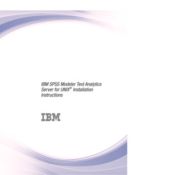
Build the Process HierarchyBreak Down the Process Flow - Interview CandidatesWe now have only one more process to model. Create the shapes illustrated in the screen shot belowwith the appropriate names and types. Use the previous steps to help you create the shapes.There are two last shapes to add to this process. If the candidate is accepted after the interview, then thehiring manager will offer the position to the candidate. However, if the candidate is not suitable for thejob, then the process will end immediately. These occurrences will be represented by end events.End events are used to mark the final termination of a particular flow of work. In our model, the end shapeindicates the end of the process of hiring new employees. An end shape with the type Message willrepresent the acceptance notification that is sent to the client. An end shape with the type Terminate willrepresent the candidate's rejection, since the hiring process will not continue past that point.1. Create two End shapes with the names "Notify candidate of acceptance" and "RejectCandidate".2. Right-click the "Reject Candidate" shape and select Terminate to indicate the type of event.Select the Message type for the remaining end shape.3. Follow the instructions from the previous page to link the BPMN shapes according to the diagrambelow:We have now completed the breakdown of processes for our model.Tutorial 2012 Interfacing Technologies CorporationBPMNTUT-08201218
Review Process Inputs and OutputsReview Process Inputs and OutputsIn order to complete the process map we need to represent the flow of work through the model. For this,we will use Materials, which represent the documents, pieces of data, or objects used within the flow ofwork. They can also be referred to as the inputs and/or outputs of BPMN shapes.Each input or output of a BPMN shape must be represented by a Material attached to a process link. Thislink shape is directional: the way it is attached to a shape indicates the direction of the flow of workthrough the business process model.First, let us consider the inputs and outputs of the various processes in our model. The following tablesummarizes these. (You may wish to review the tutorial step “Break down the process flow - Develop JobDescription”.)ProcessDevelopInputRequest for EmployeesOutputJob DescriptionInitiate RecruitmentJob descriptionJob ApplicationInterviewJob ApplicationAcceptance NotificationCandidatesThe flow of work in our model starts with HR receiving a notification that another department requires anew employee, and so we can say that Request for Employees is the input for the Develop JobDescription process (as well as for Hire New Employees), and the job description is the output of thatprocess. The job description is also the input of the process Initiate Recruitment which distributes the jobdescriptions and receives job applications. These job applications are the output of the process InitiateRecruitment and the input of the process Interview Candidates. At the end of the last process, twomessages can be sent, an acceptance or a rejection notification. However, since the rejection notificationleads to the Terminate end event (because the process does not, and could not, continue past
The following tutorial will take you through the basic steps in creating a simple process model using the Interfacing BPMN Modeler. The purpose of the tutorial is to illustrate some key modeling concepts and also to show you how to properly construct a process model. The estimated time to complete the tutorial is 1½ to 2 hours.