Transcription
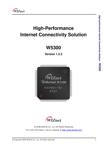
STM32F103xC, STM32F103xD,STM32F103xEHigh-density performance line Arm -based 32-bit MCU with 256 to 512KBFlash, USB, CAN, 11 timers, 3 ADCs, 13 communication interfacesDatasheet production dataFeatures Core: Arm 32-bit Cortex -M3 CPU––WLCSP6472 MHz maximum frequency, 1.25 DMIPS/MHz(Dhrystone 2.1) performance at 0 wait statememory accessSingle-cycle multiplication and hardwaredivision Memories––––256 to 512 Kbytes of Flash memoryup to 64 Kbytes of SRAMFlexible static memory controller with 4 ChipSelect. Supports Compact Flash, SRAM,PSRAM, NOR and NAND memoriesLCD parallel interface, 8080/6800 modes Clock, reset and supply management––––––2.0 to 3.6 V application supply and I/OsPOR, PDR, and programmable voltage detector(PVD)4-to-16 MHz crystal oscillatorInternal 8 MHz factory-trimmed RCInternal 40 kHz RC with calibration32 kHz oscillator for RTC with calibration Low power––Sleep, Stop and Standby modesVBAT supply for RTC and backup registers–––––Up to four 16-bit timers, each with up to 4IC/OC/PWM or pulse counter and quadrature(incremental) encoder input2 16-bit motor control PWM timers with deadtime generation and emergency stop2 watchdog timers (Independent and Window)SysTick timer: a 24-bit downcounter2 16-bit basic timers to drive the DAC Up to 13 communication interfaces––––––Up to 2 I2C interfaces (SMBus/PMBus)Up to 5 USARTs (ISO 7816 interface, LIN, IrDAcapability, modem control)Up to 3 SPIs (18 Mbit/s), 2 with I2S interfacemultiplexedCAN interface (2.0B Active)USB 2.0 full speed interfaceSDIO interfaceTable 1.Device summaryConversion range: 0 to 3.6 VTriple-sample and hold capabilityTemperature sensorReference DMA: 12-channel DMA controllerSupported peripherals: timers, ADCs, DAC,SDIO, I2Ss, SPIs, I2Cs and USARTs Debug mode–– Up to 11 timers ECOPACK packages 2 12-bit D/A converters–LFBGA100 10 10 mmLFBGA144 10 10 mm CRC calculation unit, 96-bit unique ID 3 12-bit, 1 µs A/D converters (up to 21channels)–––LQFP64 10 10 mm,LQFP100 14 14 mm,LQFP144 20 20 mmPart numberSTM32F103xCSTM32F103RC STM32F103VCSTM32F103ZCSTM32F103xDSTM32F103RD STM32F103VDSTM32F103ZDSTM32F103xESTM32F103RE STM32F103ZESTM32F103VESerial wire debug (SWD) & JTAG interfacesCortex -M3 Embedded Trace Macrocell Up to 112 fast I/O ports–51/80/112 I/Os, all mappable on 16 externalinterrupt vectors and almost all 5 V-tolerantJuly 2018DS5792 Rev 131/143www.st.com
ContentsSTM32F103xC, STM32F103xD, STM32F103xEContents1Introduction . . . . . . . . . . . . . . . . . . . . . . . . . . . . . . . . . . . . . . . . . . . . . . . . 92Description . . . . . . . . . . . . . . . . . . . . . . . . . . . . . . . . . . . . . . . . . . . . . . . . 102/1432.1Device overview . . . . . . . . . . . . . . . . . . . . . . . . . . . . . . . . . . . . . . . . . . . . 112.2Full compatibility throughout the family . . . . . . . . . . . . . . . . . . . . . . . . . . 142.3Overview . . . . . . . . . . . . . . . . . . . . . . . . . . . . . . . . . . . . . . . . . . . . . . . . . 152.3.1Arm Cortex -M3 core with embedded Flash and SRAM . . . . . . . . . . 152.3.2Embedded Flash memory . . . . . . . . . . . . . . . . . . . . . . . . . . . . . . . . . . . 152.3.3CRC (cyclic redundancy check) calculation unit . . . . . . . . . . . . . . . . . . 152.3.4Embedded SRAM . . . . . . . . . . . . . . . . . . . . . . . . . . . . . . . . . . . . . . . . . 152.3.5FSMC (flexible static memory controller) . . . . . . . . . . . . . . . . . . . . . . . . 152.3.6LCD parallel interface . . . . . . . . . . . . . . . . . . . . . . . . . . . . . . . . . . . . . . 162.3.7Nested vectored interrupt controller (NVIC) . . . . . . . . . . . . . . . . . . . . . . 162.3.8External interrupt/event controller (EXTI) . . . . . . . . . . . . . . . . . . . . . . . 162.3.9Clocks and startup . . . . . . . . . . . . . . . . . . . . . . . . . . . . . . . . . . . . . . . . . 162.3.10Boot modes . . . . . . . . . . . . . . . . . . . . . . . . . . . . . . . . . . . . . . . . . . . . . . 172.3.11Power supply schemes . . . . . . . . . . . . . . . . . . . . . . . . . . . . . . . . . . . . . 172.3.12Power supply supervisor . . . . . . . . . . . . . . . . . . . . . . . . . . . . . . . . . . . . 172.3.13Voltage regulator . . . . . . . . . . . . . . . . . . . . . . . . . . . . . . . . . . . . . . . . . . 172.3.14Low-power modes . . . . . . . . . . . . . . . . . . . . . . . . . . . . . . . . . . . . . . . . . 182.3.15DMA . . . . . . . . . . . . . . . . . . . . . . . . . . . . . . . . . . . . . . . . . . . . . . . . . . . . 182.3.16RTC (real-time clock) and backup registers . . . . . . . . . . . . . . . . . . . . . . 182.3.17Timers and watchdogs . . . . . . . . . . . . . . . . . . . . . . . . . . . . . . . . . . . . . . 192.3.18I²C bus . . . . . . . . . . . . . . . . . . . . . . . . . . . . . . . . . . . . . . . . . . . . . . . . . . 212.3.19Universal synchronous/asynchronous receiver transmitters (USARTs) 212.3.20Serial peripheral interface (SPI) . . . . . . . . . . . . . . . . . . . . . . . . . . . . . . . 212.3.21Inter-integrated sound (I2S) . . . . . . . . . . . . . . . . . . . . . . . . . . . . . . . . . . 212.3.22SDIO . . . . . . . . . . . . . . . . . . . . . . . . . . . . . . . . . . . . . . . . . . . . . . . . . . . 222.3.23Controller area network (CAN) . . . . . . . . . . . . . . . . . . . . . . . . . . . . . . . 222.3.24Universal serial bus (USB) . . . . . . . . . . . . . . . . . . . . . . . . . . . . . . . . . . . 222.3.25GPIOs (general-purpose inputs/outputs) . . . . . . . . . . . . . . . . . . . . . . . . 222.3.26ADC (analog to digital converter) . . . . . . . . . . . . . . . . . . . . . . . . . . . . . . 222.3.27DAC (digital-to-analog converter) . . . . . . . . . . . . . . . . . . . . . . . . . . . . . . 232.3.28Temperature sensor . . . . . . . . . . . . . . . . . . . . . . . . . . . . . . . . . . . . . . . . 24DS5792 Rev 13
STM32F103xC, STM32F103xD, STM32F103xEContents2.3.29Serial wire JTAG debug port (SWJ-DP) . . . . . . . . . . . . . . . . . . . . . . . . . 242.3.30Embedded Trace Macrocell . . . . . . . . . . . . . . . . . . . . . . . . . . . . . . . . 243Pinouts and pin descriptions . . . . . . . . . . . . . . . . . . . . . . . . . . . . . . . . . 254Memory mapping . . . . . . . . . . . . . . . . . . . . . . . . . . . . . . . . . . . . . . . . . . 405Electrical characteristics . . . . . . . . . . . . . . . . . . . . . . . . . . . . . . . . . . . . 415.1Parameter conditions . . . . . . . . . . . . . . . . . . . . . . . . . . . . . . . . . . . . . . . . 415.1.1Minimum and maximum values . . . . . . . . . . . . . . . . . . . . . . . . . . . . . . . 415.1.2Typical values . . . . . . . . . . . . . . . . . . . . . . . . . . . . . . . . . . . . . . . . . . . . . 415.1.3Typical curves . . . . . . . . . . . . . . . . . . . . . . . . . . . . . . . . . . . . . . . . . . . . 415.1.4Loading capacitor . . . . . . . . . . . . . . . . . . . . . . . . . . . . . . . . . . . . . . . . . 415.1.5Pin input voltage . . . . . . . . . . . . . . . . . . . . . . . . . . . . . . . . . . . . . . . . . . 415.1.6Power supply scheme . . . . . . . . . . . . . . . . . . . . . . . . . . . . . . . . . . . . . . 425.1.7Current consumption measurement . . . . . . . . . . . . . . . . . . . . . . . . . . . 425.2Absolute maximum ratings . . . . . . . . . . . . . . . . . . . . . . . . . . . . . . . . . . . . 435.3Operating conditions . . . . . . . . . . . . . . . . . . . . . . . . . . . . . . . . . . . . . . . . 445.3.1General operating conditions . . . . . . . . . . . . . . . . . . . . . . . . . . . . . . . . . 445.3.2Operating conditions at power-up / power-down . . . . . . . . . . . . . . . . . . 455.3.3Embedded reset and power control block characteristics . . . . . . . . . . . 455.3.4Embedded reference voltage . . . . . . . . . . . . . . . . . . . . . . . . . . . . . . . . . 465.3.5Supply current characteristics . . . . . . . . . . . . . . . . . . . . . . . . . . . . . . . . 465.3.6External clock source characteristics . . . . . . . . . . . . . . . . . . . . . . . . . . . 585.3.7Internal clock source characteristics . . . . . . . . . . . . . . . . . . . . . . . . . . . 625.3.8PLL characteristics . . . . . . . . . . . . . . . . . . . . . . . . . . . . . . . . . . . . . . . . 645.3.9Memory characteristics . . . . . . . . . . . . . . . . . . . . . . . . . . . . . . . . . . . . . 645.3.10FSMC characteristics . . . . . . . . . . . . . . . . . . . . . . . . . . . . . . . . . . . . . . . 665.3.11EMC characteristics . . . . . . . . . . . . . . . . . . . . . . . . . . . . . . . . . . . . . . . . 865.3.12Absolute maximum ratings (electrical sensitivity) . . . . . . . . . . . . . . . . . 875.3.13I/O current injection characteristics . . . . . . . . . . . . . . . . . . . . . . . . . . . . 885.3.14I/O port characteristics . . . . . . . . . . . . . . . . . . . . . . . . . . . . . . . . . . . . . . 895.3.15NRST pin characteristics . . . . . . . . . . . . . . . . . . . . . . . . . . . . . . . . . . . . 945.3.16TIM timer characteristics . . . . . . . . . . . . . . . . . . . . . . . . . . . . . . . . . . . . 955.3.17Communications interfaces . . . . . . . . . . . . . . . . . . . . . . . . . . . . . . . . . . 965.3.18CAN (controller area network) interface . . . . . . . . . . . . . . . . . . . . . . . . 1065.3.1912-bit ADC characteristics . . . . . . . . . . . . . . . . . . . . . . . . . . . . . . . . . . 106DS5792 Rev 133/1434
Contents6STM32F103xC, STM32F103xD, STM32F103xE5.3.20DAC electrical specifications . . . . . . . . . . . . . . . . . . . . . . . . . . . . . . . . 1115.3.21Temperature sensor characteristics . . . . . . . . . . . . . . . . . . . . . . . . . . . 113Package information . . . . . . . . . . . . . . . . . . . . . . . . . . . . . . . . . . . . . . . 1146.1LFBGA144 package information . . . . . . . . . . . . . . . . . . . . . . . . . . . . . . 1146.2LFBGA100 package information . . . . . . . . . . . . . . . . . . . . . . . . . . . . . . 1176.3WLCSP64 package information . . . . . . . . . . . . . . . . . . . . . . . . . . . . . . . 1206.4LQFP144 package information . . . . . . . . . . . . . . . . . . . . . . . . . . . . . . . . 1226.5LQFP100 package information . . . . . . . . . . . . . . . . . . . . . . . . . . . . . . . . 1266.6LQFP64 package information . . . . . . . . . . . . . . . . . . . . . . . . . . . . . . . . . 1296.7Thermal characteristics . . . . . . . . . . . . . . . . . . . . . . . . . . . . . . . . . . . . . 1326.7.1Reference document . . . . . . . . . . . . . . . . . . . . . . . . . . . . . . . . . . . . . . 1326.7.2Selecting the product temperature range . . . . . . . . . . . . . . . . . . . . . . . 1337Ordering information . . . . . . . . . . . . . . . . . . . . . . . . . . . . . . . . . . . . . . 1358Revision history . . . . . . . . . . . . . . . . . . . . . . . . . . . . . . . . . . . . . . . . . . 1364/143DS5792 Rev 13
STM32F103xC, STM32F103xD, STM32F103xEList of tablesList of tablesTable 1.Table 2.Table 3.Table 4.Table 5.Table 6.Table 7.Table 8.Table 9.Table 10.Table 11.Table 12.Table 13.Table 14.Table 15.Table 16.Table 17.Table 18.Table 19.Table 20.Table 21.Table 22.Table 23.Table 24.Table 25.Table 26.Table 27.Table 28.Table 29.Table 30.Table 31.Table 32.Table 33.Table 34.Table 35.Table 36.Table 37.Table 38.Table 39.Table 40.Table 41.Table 42.Table 43.Device summary . . . . . . . . . . . . . . . . . . . . . . . . . . . . . . . . . . . . . . . . . . . . . . . . . . . . . . . . . . 1STM32F103xC, STM32F103xD and STM32F103xE featuresand peripheral counts . . . . . . . . . . . . . . . . . . . . . . . . . . . . . . . . . . . . . . . . . . . . . . . . . . . . . 11STM32F103xx family . . . . . . . . . . . . . . . . . . . . . . . . . . . . . . . . . . . . . . . . . . . . . . . . . . . . . 14High-density timer feature comparison . . . . . . . . . . . . . . . . . . . . . . . . . . . . . . . . . . . . . . . . 19High-density STM32F103xC/D/E pin definitions. . . . . . . . . . . . . . . . . . . . . . . . . . . . . . . . . 31FSMC pin definition . . . . . . . . . . . . . . . . . . . . . . . . . . . . . . . . . . . . . . . . . . . . . . . . . . . . . . 38Voltage characteristics . . . . . . . . . . . . . . . . . . . . . . . . . . . . . . . . . . . . . . . . . . . . . . . . . . . . 43Current characteristics . . . . . . . . . . . . . . . . . . . . . . . . . . . . . . . . . . . . . . . . . . . . . . . . . . . . 43Thermal characteristics. . . . . . . . . . . . . . . . . . . . . . . . . . . . . . . . . . . . . . . . . . . . . . . . . . . . 44General operating conditions . . . . . . . . . . . . . . . . . . . . . . . . . . . . . . . . . . . . . . . . . . . . . . . 44Operating conditions at power-up / power-down . . . . . . . . . . . . . . . . . . . . . . . . . . . . . . . . 45Embedded reset and power control block characteristics. . . . . . . . . . . . . . . . . . . . . . . . . . 45Embedded internal reference voltage . . . . . . . . . . . . . . . . . . . . . . . . . . . . . . . . . . . . . . . . . 46Maximum current consumption in Run mode, code with data processingrunning from Flash . . . . . . . . . . . . . . . . . . . . . . . . . . . . . . . . . . . . . . . . . . . . . . . . . . . . . . . 47Maximum current consumption in Run mode, code with data processingrunning from RAM. . . . . . . . . . . . . . . . . . . . . . . . . . . . . . . . . . . . . . . . . . . . . . . . . . . . . . . . 47Maximum current consumption in Sleep mode, code running from Flash or RAM. . . . . . . 49Typical and maximum current consumptions in Stop and Standby modes . . . . . . . . . . . . 50Typical current consumption in Run mode, code with data processingrunning from Flash . . . . . . . . . . . . . . . . . . . . . . . . . . . . . . . . . . . . . . . . . . . . . . . . . . . . . . . 53Typical current consumption in Sleep mode, code running from Flash orRAM . . . . . . . . . . . . . . . . . . . . . . . . . . . . . . . . . . . . . . . . . . . . . . . . . . . . . . . . . . . . . . . . . . 54Peripheral current consumption . . . . . . . . . . . . . . .
Memories – 256 to 512 Kbytes of Flash memory – up to 64 Kbytes of SRAM – Flexible static memory controller with 4 Chip Select. Supports Compact Flash, SRAM, PSRAM, NOR and NAND memories – LCD parallel interface, 8080/6800 modes Clock, reset and supply management – 2.0 to 3.6 V application supply and I/Os – POR, PDR, and programmable voltage detector (PVD) – 4-to-16 MHz .