Transcription
Varia437Soil mechanics and foundationengineering R&D for roadsand bridges.A summary of activities in th Northernand some Western European countries.Bengt RydellMay 1996Statens geotekniska institutSwedish Geotechnical Institute
S-581 93 Linkoping, SwedenTel. 013-11 51 00, Int. 46 13 11 51 00Fax. 013-13 16 96, Int 46 13 13 16 96ISSN 1100-6692
PREFACEClose co-operation in the field of geotechnical research has existed for many years between theSwedish Road Administration (SNRA) and the Swedish Geotechnical Institute (SGI). In 1993a seminar on road design, construction and maintenance related R&D was held with invitedresearchers from the Nordic countries. As the offshoot of discussions between SNRA and SGI,an international seminar on soil mechanics R&D for roads and bridges was found to bevaluable. The objective of this seminar was to stimulate and encourage co-operation betweenEuropean countries.An invitation was send to a ten countries in the Northern and Western of Europe. The seminarwas arranged by an Organizing Committee with participants from the SNRA and SGI. Themeeting was held in November 16-18, 1993, in Sigtuna, Sweden.This report contains papers, National Reports on ongoing R&D and other publications used atthe seminar.Linkoping in May 1995Bengt RydellEditorsemr&b\varia\preface.doc
SGI Varia 437Seminar on Soil Mechanics on R&D for Roads and Bridges.National Reports, Literature and Technical PapersCONTENTSPreface1.National Reports - R&D-activitiesBelgiumDenmarkFinlandFranceItalyThe NetherlandsNorwaySwedenUnited Kingdom2.Geotechnical designTechnical papersLiterature and references3.Foundation engineeringTechnical papersLiterature and references4.Environmental geotechnicsTechnical papersLiterature and references5.MiscellaneousTechnical papersLiterature and referencessem r&b\varia\contents.doc
1.NATIONAL REPORTS - R&D-ACTIVITIESThe participants were required to write a document describing the ongoing and plannedresearch in each country about the chosen topics. These National Reports were thendistributed to the chairmen of the plenary sessions for the preparation of a summary report.The National Reports as well as the summary reports was compiled and distributed to theparticipants at the beginning or the seminar.In the following, the National Reports are published in the original form provided by therepresentative from the participating countries. In addition, references to researchprogrammes and annual reports from research organizations are given.
National ReportR&D activitiesBelgium
BelgiumReferences:Dynamic soil improvement methods 1)Prof Dr ir W F van lmpe, ir Wim Haegeman, Prof Dr MR Madhav, ir P MengeAnalysis and settlement of dilating stone column reinforced soil 1)Prof Dr ir W F van Impe, Prof Dr MR MadhavLoad transfer through a gravel bed on stone column reinforced 1)Prof Dr MR Madhav, Prof Dr ir W F van ImpeDMT-measurements around PCS-piles in BelgiumResearch ass H Pfeiffer, Prof Dr ir W F van lmpe, G Cortvrindt, M Bottiau1)Abstract and conclusions included. A copy of the paper can be ordered fromthe Swedish Geotechnical Institute, S-581 93 Linkoping.
SEMINAR ON SOIL MECHANICS AND FOUNDATIONENGINEERING R&D FOR ROADS AND BRIDGESThe soil mechanics' research in the Flemish part of Belgium,concentrated at Ghent University, is dealing with several topicssuch as :a)SASWb)Calibration chamber testing for vertical cyclic loading onmodel pilesAccoustic penetrometer developmentPile drivability analysis with excess pore water pressurecompleted modelsWaste disposal soil improvement by heavy tampingDilatancy effects in stone columnsResonant frequency and vibrocompaction methodsDMT - as an evaluation of pile installation quality.c)d)e)f)g)h)On almost each of those topics, papers or doctoral work havebeen published recently. Some of those papers are enclosed here.With respect to R&D for roads I believe the most relevant re search topic in this list is probably the SASW-research.As a separate enclosure some results and general ideas aboutthis topic have been given.Sincerely yours, :··Prof. Dr ir W.F. VAN IMPE.
Proc. Seminar on Soil Dynamics and Geotechnical Earthquake Engineering, 26-29 July 1992, Lisboa-PortDYNAMIC SOIL IMPROVEMENT METHODSProf Dr W.F. VAN IMPE 1 and Ir W. HAEGEMAN 2Prof Dr M.R. MADHAV 3 and Ir. P. MENGE 4ABSTRACTAmong the permanent soil improvement methods, an important category of techniques is dealingwith the application of longitudinal and shear waves to the ground layer to be improved. Some ofthose methods are only meant for superficial or undeep soil layer compaction, many othersalthough can also be classified among the deep soil improvement methods.The aim of this paper is to discuss last mentioned techniques establishing some of theirparticular requirements, advantages and disavantages.CONCLUSIONDuring the last decade, the use of soil improvement techniques has become, without doubt,·one of the greatest challenges for the foundation engineer.In the design of an adequate soil improvement method for a specific application, thedeciding factors must be the available experience of the contractor concerned, the influenceon the environment, the total energy cost and the expected improvement of the soilcharacteristics.In many cases, economic reasons dictate that the more common soil improvement techniquesare preferred over the more sophisticated foundation systems with which deeper, resistantlayers are reached. Therefore, it is becoming increasingly important to understand clearly thetechnical possibilities and the geotechnical background of each improvement technique. Manyof them began and were futher developed starting only with experimental data.As it appears for the moment, the most relevant steps in understanding soil improvement havebeen made with respect to vibratory compaction techniques. Many of the other methodsincreased comparably their justified share on the market of equivalent foundation engineeringjobs, but usually less has been done in order to gather good data for a more profound analysisof understanding.A new promissing geotechnical engineering field related to soil improvement is the oneconcerning waste disposal treatment. This topic has been already included is some moreelaborated research programs; one can fortunately expect therefore quickly progressingunderstanding to become available in the near future.1)2)3)4)Director Soil Mechanics Laboratory, Ghent University Belgium,Full Professor at Ghent University; Full Professor at Catholic University of Leuven.Assistant Soil Mechanics Laboratory, Ghent University, Belgium. Research Engineer.Professor of Civil Engineering, Ind. Institute of Technology, Kanpur, India.Research assistant Belgian National Fund for Scientific Research Soil MechanicalLaboratory, Ghent University Belgium.
Osterreichische Ingenieur- und Architekten-Zeitschrift (OIAZ), 137. Jg.Heft 3/1992 - Seiten 114-121ANALYSIS AND SETTLEMENT OF DILATING STONECOLUMN REINFORCED SOILW.F. VAN IMPE 1) and M.R. MAD HAV 2)ABSTRACTUse of stone columns or granular piles in end bearing conditions for improving the bearingcapacity, settlement, and resistance to liquefaction of soft clays or loose deposits has becomecommon practice. Most of the available methods for stability analysis and for prediction ofsettlements of granular pile reinforced soil, are based on an elastic approach. In this paper thedensified stone column material is considered to be at the limit yielding condition and hencedilating. Results obtained bring out the importance of incorporating the dilatancy effects on theprediction of settlement and the stresses on the stone column and the soil. Induced lateralstresses in the soil adjacent to the column are shown to be of the same order as the verticalstresses. The predictions of settlements based on the proposed approach appear to agreereasonably well with measurements.CONCLUSIONSOptimal design of stone columns requires an optimum stress concentration factor. The densegranular material dilates while yielding at peak stresses. Granular pile reinforced soil in here isanalysed through a unit cell consisting of a stone column surrounded by the in situ soil. Themodel proposed incorporates the dilatancy of the stone columns material and the axial symme tric geometry of the problem. Results obtained show the significant beneficial effect of thedilatancy on the settlement reduction and stresses transferred to the pile. As a result, even atonly 0.5 % dilatancy, the settlement of the reinforced soil is further reduced compared to acase in which the column is supposed to yield at constant volume (critical state condition). Thestress ratio K of the in situ soil at the column-soil interface is close to unity indicating condi tions very different from K 0 -condition.The predictions compare well with measured settlements so validating the approach presentedhere.(1)(2)Professor Soil Mechanics and Foundation Engineering, Director of the Soil MechanicsDepartment, Ghent State University, Ghent; Professor Soil Mechanics at LeuvenCatholic University, Belgium.Professor of Civil Engineering, Ind. Institute of Technology, Ranpur, India
LOAD TRANSFER THROUGH AGRAVEL BED ON STONE COLUMN REINFORCEDSOILMADHIRA R. MADHAV 1 AND W.F. VAN IMPE 2ABSTRACTTreatment of soft or weak deposits with stone columns involves providing on top a densegravel bed as a working platform and as a drainage layer acting as a stiff raft. It is oftenpresumed to be rigid while no data are available to validate this statement. A simple model isproposed here for the analysis of such granular layer covering the stone column reinforced soil.The response of the system is shown to depend on the relative stiffness of the gravel bed. Theload transferred to the stone column varies significantly with the relative stiffness of the gravelbed to those of the column and the soil. The design criterion proposed here ensures the gravelbed to deform more uniformly.CONCLUSIONSImprovement of ground with a regular array of stone columns is commonly resorted to in casesignificant reduction in settlement is desired. A unit cell is analysed as typical of the treatedarea. The design usually implies uniform settlement of the stone column and the soft soil. Asimple model for a gravel bed laid over the stone column reinforced soil is proposed andanalysed for both plane strain (granular trench) and axi-symmetric (stone column) conditions.The variation of settlements with distance in a unit cell are shown to be dependent on the shearstiffness (product of shear modulus and the thickness) of the gravel bed, the relative stiffness ofthe stone column to that of soft soil, and the spacing of the stone columns. The loadtransferred to the stone column by the gravel bed also varies with the above specifiedparameters. For the covering gravel bed over stone columns to be considered rigid, the relativestiffness ratio, Ac, should be less than about 0.2. For higher values of Ac differential settlementscould be significant.1)Professor of Civil Engineering, Indian Institute of Technology, Kanpur-208016,INDIA2)Professor of Soil Mechanics and Foundation Engineering & Director of SoilMechanics Department, Gent University, Gent, BELGIUM.
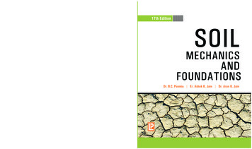
XIII ICSMFE, 1994. New Delhi, India/ XIII CIMSTF, 1994. New Delhi, lndcDMT-MEASUREMENTS AROUND PCS-PILES IN BELGIUMEVALUATION DES PIEUX PCS EN BELGIQUE BASEE SUR DES ESSAIS DMTH. PEIFFERResearch Assistent N.F.S.R., Ghent University, BelgiumW.F. VAN IMPEProfessor - Director of Soil Mechanics Laboratory, Ghent University, BelgiumProfessor Leuven Catholic University, BelgiumG. CORTVRINDTSocofonda S.A., Brussels, BelgiumM. BOTTIAUSocofonda S.A., Brussels, BelgiumSYNOPSIS : This paper evaluates the soil stress changes around a Socofonda PCS auger pile using the dilatometer test.Results of three test sites are reported. The evaluation of the execution parameters and other external influences are gathered through DMT-measurementsduring installation of the pile. The paper further describes a comparison of the results of soil investigation at different stages before, during and after pileinstallation.in which:V, concrete volume consumptionv, theoretical volume of the pile with known nominal dimensions.INTRODUCTIONThe bearing capacity, especially the shaft friction, of auger piles isstrongly dependent on the execution parameters of the pile. PCS- piles(Pressurized Concrete Screw-piles) installed with a continuous auger arebrought to depth causing no or a very Iimited soil displacement. Duringcasting the concrete, an additional pressure is applied on the fresh concre te. For this type of pile, the execution parameters are the downward forceduring penetration N;, the torque M,, rotation speed (downwards) 11;,downward velocity of the auger V;, upward velocity v., upward force N.,concrete pressure a\, the ratio diameter auger to diameter stem, the pitch(for alle the discussed piles, p was 45 cm) of screwing down, and thequality of the concrete and the way of casting. This is an important factorgoverning the arching effect and determining the real fresh concretepressure in equilibrium with the total horizontal soil stresses. By the useof hyperplastifiers, the W /C ratio can he limited to 0.45 and the cubicstrength nowadays reaches 45N/mni2 and higher.All of these parameters are continuously measured (each 80 mm) duringpile installation.TYPE OF PILEGenerally the PCS-auger piles are using an inner stem diameter of 100mm. During casting of the concrete an overpressure of 2 to 4 bar isapplied on the fresh concrete, while the auger is regained slowly. Thisprocedure doesn't cause vibrations. After casting the concrete, the reinfor cement is brought into the pile using a vibrator. Eventual difficulties canbe avoided using a greater inner stem diameter. So the reinforcement canbe placed inside before casting the concrete. The outer diameter for suchpiles ranges between 35 and 45 cm. The high torque (100 kNm) that canbe applied avoids excavating too much of soil and allows for penetrationin resistant hearing layers. The degree of soil displacement can be dedu ced out of the overconsumption (occ) of concrete, defined as :occ vb-vpVPx JOO (in%)(I)This parameter (occ) gives a mean value and hides local effects such aslenses or layers ,where a higher excavation and/or soil displacementresulting in varying concrete consumption exists. For the discussed piles,the overconsumption was I 6 % for the test site at Oudenaardc, 28 % forDcndermondc and 95 % for Docl-test sites. The high overconsumption atDoc! is mainly due to the fact that the upper layer (0 to -8.00) is compo sed of dredged material and to the presence of another very soft layer onthe levels from -8,70 to -10.30.SOIL TEST PROGRAMFor each pile, the following test soil results arc gathered : (CPT) electri cal cone penetration test before execution of the pile ; (DMTI-A) DMT test before installation of the pile at 1,5 times pile diameter out of thecenter of the pile. In addition, during installation of the pile, a DMTI-Btest is performed with the DMT-blade installed at a fixed depth. The A rcading of the DMT curve was considered equivalent to an oedometertime-deformation curve. Using Casagrande's log t/fitting method : t,ro.,.was determined before the start of the piles installation. Pile installationstarted when the decreasing ratio of A-readings became less than 5kPa/hour. By this, consolidation and relaxation, due to the installation ofthe DMT blade did only have a ncglcgeable influence on the measure ments lateron during pile installation. Finally a (DMT-1-C) test after in stallation of the pile at 1,5 times pile diameter out of the center of the pilewas performed. The membrane is oriented towards the pile shaft.For the orientation of the blade, one has two possibilities :radial position (membrane towards the pile). The advantage here isthe direct measurement of horizontal stress variation. For large soildisplacements, arching effect can occur around the blade.tangential position : the advantage is a smaller disturbance of theinitial stress field around the pile. On the other hand as long as noclear relationship exists between the principle stress changes, the
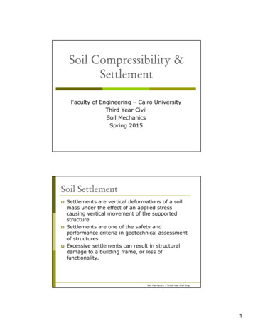
interpretation of such DMT readings with tangential blade orientationmainly stays difficult.D - DMT - 1B. measurementDMT hstalled at depth 0:: 75rllThe aim of this research program was to evaluate the effect of PCS pileinstallation, in sandy layers, on the surrounding soil stress field.DISCUSSION OF TIIE TEST SITESJ.Docl-tcst site-;;;The results of this test site, with all of the difficulties linked normally toeach new research experience have been discussed in an earlier paperPeiffer et al (1991).250 f-2:C).,, 200Cl' CDcndcrmonde-tcst site'gThe results of the field tests are given in Fig. I a,b,c and 2. eCONSTRAINED .ttOOUt.USHORI'ZONTRL(bbr) TRCSS INOCX 00800l: O,ot;;.,------; ,,i---,2 10-::------;;;lzso"'·----- m- ----300-1-.,.Time (minlFig. le. DMT-IB result at ,nlkPolE s.B0.QJCl,z12151500-100M l/m.v3sG200 i.ooe 250500 0Down.,nrtltorqueRotationalspeed o ellr/minl25 soVerlico lpcnelroHonspeedlm/Hl0250SOO1aI dPCS-pile-Oeooermonde -OHT-IA (before)---OHT·1C (after)Fig. la. DMT-results at Dendermondeqc (MPal1214160.1fs IHPal0.204-.-.-----. -ctcyeysandvery de lo saridme lh.rn Ol/\Seto very16dense sondFig. lb. Initial CPT at test siteFrom the linearly increasing CPT in the sandlayers where the DMT (1-B)is installed, it becomes evident the sandlayer was normally consolidated.The starting DMT A-reading is sligthly higher than expected probably dueto the local increased stress field around the blade. The DMT-membraneis directed towards the pile centre. The screwing-in energy resulting inFig. 2. PCS-pile installation parameters at Dendermonde test sitevery high downward penetration in the cohesive top layers, induces excesspore ·water pressures and "heavy liquid pressures which compensate anormally expected soil rell!JCation. When the auger passes by at DMT level, the whole of the remoulded soil column along the auger being moreor less in suspension, induces for the rest of the screwing down move ment a remarkable total stress increase (water pressure increase). One socan easily explain an input of total stress increase of order of :;; 30 k.Pa.Obviously, the water overpressure fades out with time. During the castingprocess the. total stresses, induced by the fresh concrete are detected,expecially again starting at the level of the blade. The final DMT A rcading is apparantly flattening out at about 160 kPa, being almost 50 kPahigher than the starting value. From this point of view this pile systemwould be somewhat beneficial to the soil-condition. One however must becareful since only DMT A-readings, performed some days after pileinstallation would indicate reliable more results. In Fig. 2 DMTI-A/l·Cone sees such difference between the DMT-test before and after full pileinstallation indicating that there is almost no change in horizontal stressindex and constrained modulus.
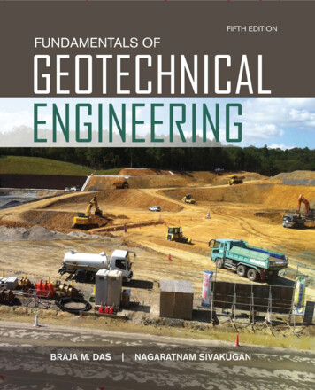
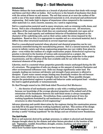
Oudcnaardc-tcst siteCXDENAAR0E - DMT -1 B measurementsDMT. nstalled at depth. 0:: 710mTwo piles were examined at this site; piles n 205 and n 207.The results arc gathered in Fig. 3,4 and 5. - CXiT tangdialPie. n.0 205Lpile 13m 04678l1' 12 131211 ii1000.1214-"'::1:0Fig. 3a. DMT-results at Oudenaarde.11"'g' 2SOCONSTRJUNED HOOULUCHORIZ.OHTRt.Clar)STRCSS lHDEX0 'oCllf:'. {e z.s s 1.s 1a200. II,-.L---t-- ---- . . ,., e1 ·,.a.8"rn5Q7L. .,.,80 ----''-----90cf-:---. . .Time (min)HIIFig. 4b. DMT 1B pile121.3.f205 result at Oudenaarde13i00008M 1/m.vPCS-pile-0udenoordeAugerOownwcird 'ingspeedspeed{m/HllMPalltr/minl(m/HlZOO 400 B 256 588 8 20 6 25 56 6 256 S86111--.- e,- -., e1 .-,-.,PCS '-'-'- ,, , .,0concretepressure{kPcil2.S S 7.S 18KdDMT-1A-··· DMT·1CBFig. 3b. Initial CPT results at OudenaardelCUB-lAARr - a-IT -1 B measurementCMT hstalled at depth· ·o 720m.4002IIIIIIIIIIPie n 207li,n.x13m.c."'4sII.cIIII3., '.s)SOI'7III·III·,IIIIIIIIII234s'70 :i::ClI1 1e: 18:uJuJuI:1zIl1IIII13 --'--'-'ll., , .Fig. 5. PCS-pile n 205 installation parameters recorded at Oudenaarde160llOlime lminlFig.4a. DMT 1B pile n 207 result at OudenaardeFrom the Fig. 4b, the (tangential) DMT-!B analysis on pile n 205indicates that soil arching is built op gradually during screwing down ofthe auger, resulting in a general overall (gradual) decrease of the A-value
with some peaks in between, probably due to collapses of former archeswhile the auger continues to penetrate. The further general decrease afterDMT A-reading during casting the fresh concrete, only shows the gradualoutfading influence of the soil arching with increasing fresh concreteweight.From the readings for pile n 207, with radial DMT-IB readings, a lot ofinteresting differences with the previous analysis are shown. Over the firstfive meters, the auger penetrates with a rather small torque, but with ahigh downward velocity through the loose silt/silty sand. This results thistype of dry and only very slightly cohesive material in a dramatic decrea se of the total stress combination felt by the DMT blade. The freshconcrete passing the level of .the DMT, the concrete pressure influencestremendously the A-reading of the DMT-total stress in radial direction.Such overpressures are again fading out in time, partly compensated bythe increasing fresh concrete weight above the DMT-measurement level.COCEW.(N)E -IITable 1. Comparison of DMT-stress indexSiteMeasuredConcreteOverconsumptionKD, alter inst.Soil typeKD,befors 1.nsc.Doe!95 %1,30medium densesandOudenaarde28 %1,20medium densesand (NC)Dendermonde16%1,00medium densesand-slightly (OC)Morover, the increase of DMT-horizontal total stress in the top layer andthe decrease near the pile tip are remarkable. This is dicussed in anearlier paper Peiffer, Van Impe, Cortvrindt, Van Den Broeck (1991).Because also the pile installation parameters are available, a proposalcould be to calculate the idealized specific screwing-in energy Esc. Theuse of this specific energy value in relation to the pile installation parame ters is sugested in Van Impe (1988).PCS-ple -ArnTJI Ano'T»UtolI. ' 2'01COJICl.QJC 'i .iI-vVI16lJCONSIDERATIONS ON PILE INSTALLATION EFFECTSOur main interest in this kind of research is to finally understand muchbetter the shaft capacity of screw piles. For this purpose, the pile installa tion effects have to be evaluated more carefully with respect to theeffective soil stress changes around the shaft. Comparison between DMT1-A and DMTI-C readings gives an indication for the degree of suchstress changes in terms of total stress. Referring to the horizontal stressindex (table 1), the results of such comparison are presented for the threetest sites.PCS-pie15PCS ao;ier depth l mJFig. 7. PCS-pile installation energy and DMT A-readings as a funtion oftimeThe results of such Esc- lata can either be presented in a time relateddiagram (Fig. 6 Doe!) or an auger peneatration depth diagram (Fig. 7 Dendermonde). In these figures we can see a quite good agreementbetween DMT-A-readings and installation energy curves. For Doe!, theinput energy curve is even quite similar to the A-reading curve. Peaks ofenergy-input can also be found on the A-reading curve. For Dendermondeone sees clearly the effect of the energy-input on the horizontal stressstate when the auger passes. One also can see the influence of executiontime and time delays on the final stress-state. A similar analysis forOudenaarde and also the evaluation of screwing out energy is discussed inVan De Velde, Van Hoye (1992).The today's· analysis in this research program is also going out fromcontinuous pressure m urements at the DMTl·B blade during pileinstallation. Together with pile installation parameter, a more completestress field analysis so became available.CONCLUSIONSIn this paper the dilatometer is described as a tool that could help toevaluate the influence of pile execution parameters on the soil conditionaround the pile shaft. For PCS-piles some increase of horizontal stress ismainly dependent on the OCR, soil type, dilatant character of the soil,and predominantly on the installation details. It can be deduced that a loolow auger penetration velocity and losses of time during installation canaffect largely the final stress state around the pile.ooaREFERENCES00· o -- 11· 1,o .---LJ.,.oo .---4""·1""1",. --:::::icc:co1,,.,."--:,/-,:10·03"Tine h mnutesFig. 6. PCS-installation energy function as compared to DMT A-readingsVANDEVELDE, K. en VAN HOYE, P., 1992, Onderzoek naar hetschachtdraagvermogen van boorpalen uitgaande van dilatometerproef resultaten, GentVAN IMPE, W.F., 1988, Considerations on the auger pile design, lsteInternational Geotechnical Seminar : Deep Foundation on bored andAuger Piles, 7-10 june, Ghent,PEIFFER, H., VAN IMPE, W.F, CORTVRINDT, G. en VAN DENBROECK, M., 1991, Analysis of CFA-pile-behaviour with DMT·results at Geel test site, 4th DFI International Conference on Pilingand Deep Foundations, 7-12 April, Stresa.
National ReportR&D activitiesDenmark
Danish Geotechnical Institute2Seminar on Soil Mechanics and Foundation Engineering Research andDevelopment for Roads and BridgesInformation on the research and development work at the DanishGeotechnical Institute and in short at other Danish research organisations1. IntroductionThe present status of R&D in the actual area in Denmark is very much restricted by lack ofallocated funding for the building industry and in particular concerning the topic area. However, thevery high activity related to the on-going construction activities at Storebrelt and 0resund for majorcombined railroad and road traffic systems to some degree improve this situation.The projects being of high technical complexity are placed in Geotechnical Category 3 (EC7)calling for high requirements to the extent and quality of geotechnical investigations, design andconstruction control. 111is has caused a large number of project related development projects andintroduction of new methods and equipments. Furthermore, multidisciplinary integration ofspecialists work has provided background for progress in niches and at interfaces between f.inst.geology and geotechnics.Formally, much of the detailed information on soil and rock properties and soil-structure interactionis restricted by clients. Fortunately, a number of articles prepared on the basis of the investigationsperformed for the fixed link across Storebrelt have been released as shown in Encl 1.The Danish Geotechnical Society are publishing dgf-Bulletins containing the topics related to thepresent symposium. DGI is a main contributor to the different series on soil mechanics, foundationengineering, design practice, engineering geology and engineering geology. The present list of dgf Bulletins is copied in Encl 2.In Denmark the below-mentioned research institutes and organisations are the most importantcontributors to R&D for soil mechanics and foundation engineering related to road and bridges:DGIVD (SV)DSBAUC(FL)TUD(IGG)(IVTB)DIA (GD)Danish Geotechnical InstituteDanish State Road Directory - The State Road LaboratoryDanish State Railroad Directory - Bridge and Environmental Departments.Aalborg University Centre, Department for Water, Soil andEnvironmental Science, Foundation Laboratory.Technical University of Denmark,Department for Geology and Geotechnical EngineeringInstitute for Roads, Traffic and Planning of TownsDanish Engineering Academy - Geotechnical DepartmentBeside these a number of governmental organizations and private companies are working especiallyin environmental sciences. However, much research and development are not specifically related toroad and bridges, but deal with utilization or disposal of residues from coal-fired power plants.Also in this matter DGI has contributed with a number of references, Encl 3.Furthermore, R&D in ground water and soil pollution is the topic for the Danish EnvironmentalResearch Programme funded by 50 mill D KK over the next 3 years. Their is no connection toR&D for road and bridges in this programme.564 00478NF-JST14 November 1993
Danish Geotechnical Institute2.3DGI contributions to R&D on Soil Mechanics and Foudation Engineering for Road andBridges.DGI contributions may be exemplified by the number of 84 internal R&D projects for 1993 with abudget of 5.3 mill DKK covering personal education, participation in national and internationalR&D activities, in standardization and conferences, specific development of methods and equip ments and publication and documentation activities. The costs in taken from the overhead of theaverage yearly turnover of approx 120 mill DKK. DGI does not receive any general governmentalsupport, but deals commercially as a self-supporting fund using possible profit for R&D-activitieswithin our field of interests.2.1Geotechnical Design inclusive advanced numerical and statistical methods and field andlaboratory testing.Major DGI projects are related to international standardisation and it may of course be questionedbeing a development activity. However, we consider the international cooperation as stratetic forour development as well as for our marketing. TI1e activities have a total budget of 750,000 DKKin 1993.DGI director Niels Krebs Ovesen is chairman for the drafting panel of Eurocode 7: GeotechnicalDesign, General Rules. A number of DGI specialists are involved in r lated activities t.ex.standardisation of laboratory and field work, correlation of design practices, principles andrequirements for safety and serviceability.In connection to the 50 year anniversary of DGI an international symposium on "Limit state designin geotechnical engineering" was arranged 26-28 May 1993. The papers. keynote le
Among the permanent soil improvement methods, an important category oftechniques is dealing with the application oflongitudinal and shear waves to the ground layer to be improved. Some of those methods are only meant for superficial or undeep soil layer compaction, many others although can also be classified among the deep soil improvement methods.