Transcription
Step 2 – Soil MechanicsIntroductionWebster defines the term mechanics as a branch of physical science that deals with energyand forces and their effect on bodies. Soil mechanics is the branch of mechanics that dealswith the action of forces on soil masses. The soil that occurs at or near the surface of theearth is one of the most widely encountered materials in civil, structural and architecturalengineering. Soil ranks high in degree of importance when compared to the numerousother materials (i.e. steel, concrete, masonry, etc.) used in engineering.Soil is a construction material used in many structures, such as retaining walls, dams, andlevees. Soil is also a foundation material upon which structures rest. All structures,regardless of the material from which they are constructed, ultimately rest upon soil orrock. Hence, the load capacity and settlement behavior of foundations depend on thecharacter of the underlying soils, and on their action under the stress imposed by thefoundation. Based on this, it is appropriate to consider soil as a structural material, but itdiffers from other structural materials in several important aspects.Steel is a manufactured material whose physical and chemical properties can be veryaccurately controlled during the manufacturing process. Soil is a natural material, whichoccurs in infinite variety and whose engineering properties can vary widely from place toplace – even within the confines of a single construction project. Geotechnical engineeringpractice is devoted to the location of various soils encountered on a project, thedetermination of their engineering properties, correlating those properties to the projectrequirements, and the selection of the best available soils for use with the variousstructural elements of the project.Likewise, steel is a material whose properties generally remain unchanged during the lifeof a structure. The properties of soils can change as the amount of moisture fluctuates andother environmental influences vary. Soils can change significantly under load. Forexample, loading can increase soil density and strength if pore pressure is allowed todissipate. If pore water cannot escape, loading may drastically weaken the soil becausethe pore water, which has no shear strength, bears the load. These possible changesrequire the geotechnical engineer to predict soil behavior under anticipated load – whetherthe load is applied gradually or instantaneously.Dr. Karl Terzaghi stated in his 1943 book titled Theoretical Soil Mechanics:“. . . the theories of soil mechanics provide us only with a working hypothesis,because our knowledge of the average physical properties of the subsoil and of theorientation of the boundaries between the individual strata is always incompleteand often utterly inadequate. Nevertheless, from a practical point of view, theworking hypothesis furnished by soil mechanics is as useful as the theory ofstructures in other branches of civil engineering.”Advance planning and careful observation by the engineer during the construction processcan help fill in the gaps between working hypothesis and fact. This section of the designmanual intends to provide a basic understanding of soil mechanics so the engineer candevelop a useful “working hypothesis” for the design and use of helical screw foundations.The Soil ProfileRock or soil material, derived by geologic processes, is subject to physical and chemicalchanges brought about by the climate and other factors prevalent at the location of thesoil. Vegetation, rainfall, freeze/thaw, drought, erosion, leaching, and other natural Copyright2003 Hubbell, Inc.Helical Screw Foundation System Design Manual for New Construction 2-1A.B. Chance Company
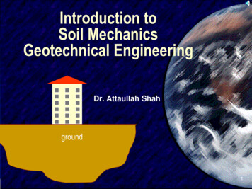
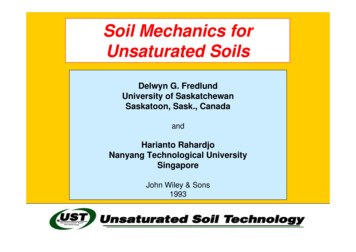
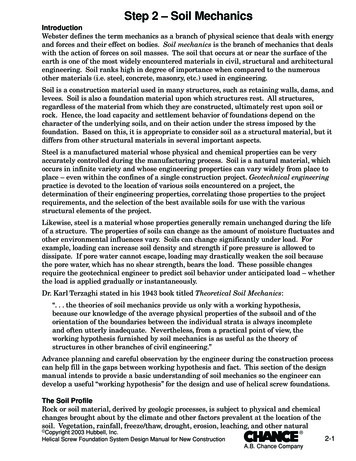
processes result in profound changes graduallytaking place in the character of the soil withthe passage of time. This development bringsabout the soil profile.The soil profile is a natural succession ofzones or strata below the ground surface. Itmay extend to various depths, and eachstratum may have various thicknesses. Theupper layer of the profile is typically rich inorganic plant and animal residues mixed witha given mineral-based soil. Soil layers belowthe topsoil can usually be distinguished by acontrast in color and degree of weathering.The physical properties of each layer usuallydiffer from each other. Topsoil is seldom usedfor construction. Deeper layers will havevarying suitability, depending on theirproperties and location. It is important torelate engineering properties to individual soillayers in order for the data to be meaningful.If data from several layers of varying strengthare averaged, the result can be misleadingand meaningless. Equally misleading is thepractice of factoring a given soil’s engineeringproperties for design. This can lead to overlyconservative foundation design.Figure 2.1Residual Soil ProfileTop SoilClaySiltSandGravelBed RockDefinition of SoilSoil is defined as sediments or other accumulation of mineral particles produced by thephysical or chemical disintegration of rock, plus the air, water, organic matter, and othersubstances that may be included. Soil is typically a non-homogeneous, porous, earthenmaterial whose engineering behavior is influenced by changes in moisture content anddensity.The origin of soil can be broken down to two basic types: residual, and transported.Residual soil is caused by the weathering (decomposition) of rock by chemical or physicalaction. Residual soils may be very thick in areas of intense weathering such as the tropics,or they may be thin or absent in areas of rapid erosion such as steep slopes. Residual soilsare usually clayey, and their properties are related to climate and other factors prevalentat the location of the soil. Residual soils are usually preferred to support foundations, asthey tend to have better, more predictable engineering properties.Transported or deposited soils are derived by the movement of soil from one location to theother by natural means. The means are generally wind, water, ice, and gravity. Thecharacter of the resulting deposit often reflects the modes of transportation and depositionand the source material. Deposits by water include alluvial floodplains, coastal plains, andbeaches. Deposits by wind include sand dunes and loess. Deposits by melting ice includeglacial till and outwash. Each of these materials has behavioral characteristics dependenton geological origin, and the geological name, such as loess, conveys much useful 2-2A.B. Chance Company Copyright2003 Hubbell, Inc.Helical Screw Foundation System Design Manual for New Construction
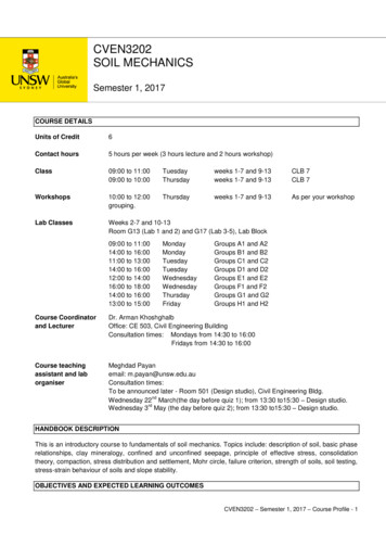
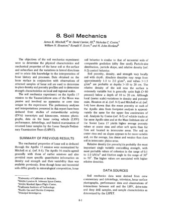
information. Transported soils – particularly by wind or water – are often of poor qualityin terms of engineering properties.Soil Volume & Density RelationshipsA soil mass is a porous material containing solid particles interspersed with pores or voids.These voids may be filled with air, water, or both. Figure 2.2 shows a conceptual diagramof relative volumes of air, water, and soil solids in a given volume of soil. Pertinentvolumes are indicated by symbols to the left while weights of these material volumes areindicated by symbols to the right. Figure 2.2 also provides several terms used to definethe relative amounts of soil, air, and water in a soil mass. Density is the weight of a unitvolume of soil. It is more correctly termed the unit weight. Density may be expressedeither as a wet density (including both soil and water) or as a dry density (soil only).Moisture Content is the ratio of the weight of water to the weight of soil solids. Porosity isthe ratio of the volume of voids to the total volume of the soil mass regardless of theamount of air or water contained in the voids. Void ratio is the ratio of the volume of voidsto the volume of soil particles. The porosity and void ratio of a soil depend upon the degreeof compaction or consolidation. For a particular soil in different conditions, the porosityand void ratio will vary and can be used to judge relative stability and load-carryingcapacity – i.e. stability and load capacity increase as porosity and void ratio decrease. Ifwater fills all the voids in a soil mass, the soil is said to be saturated.Figure 2.2Permeability or hydraulic conductivity is the property of soil allowing it to transmit water.Its value depends largely on the size and number of the void spaces, which in turn dependson the size, shape, and state of packing of the soil grains. A clay soil can have the same Copyright2003 Hubbell, Inc.Helical Screw Foundation System Design Manual for New Construction 2-3A.B. Chance Company
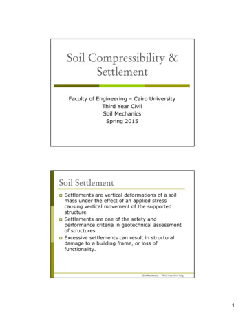
void ratio and unit weight as a sand soil, but the clay will have a lower permeability because of the much smaller pores or flow channels in the soil structure. Water drains slowlyfrom fine-grained soils like clays. As the pore water drains, clays creep, or consolidateslowly over time. Sand soils have high permeability, thus pore water will drain quickly. Asa result, sands will creep, or consolidate when loaded until the water quickly drains. Afterdrainage, the creep stops.Basic Soil TypesAs stated above, soil is typically a non-homogeneous material. The solid mineral particlesin soils vary widely in size, shape, mineralogical composition, and surface-chemicalcharacteristics. This solid portion of the soil mass is often referred to as the soil skeleton,and the pattern of arrangement of the individual particles is called the soil structure.The sizes of soil particles and the distribution of sizes throughout the soil mass areimportant factors which influence soil properties and performance. There are two basicsoil types that are defined by particle size. The first type is granular, or coarse-grainedsoils. Granular soils consist of particles that are large enough to be retained by the #200sieve (0.074 mm). The #200 sieve has 200 openings per inch. Granular soils consist ofcobbles, gravels, sands, and some silts. Granular, or coarse-grained soils are commonlyreferred to as non-cohesive, or cohesionless soils. The particles of cohesionless soilstypically do not stick together except in the presence of moisture, in which surface tensiontends to hold particles together. This is commonly referred to as apparent cohesion.The second type is fine-grained soil. Fine-grained soils consist of particles that are smallenough to pass through the #200 sieve. Typical fine-grained soils are silts and clays. Siltparticles typically range from 0.074 to 0.002 mm. Clay particles are less than 0.002 mm.It is not uncommon for clay particles to be less than 0.001 mm (colloidal size). Finegrained soils are commonly referred to as cohesive soils. The particles of cohesive soilstend to stick together due to molecular attraction.For convenience in expressing the size characteristics of the various soil fractions, anumber of particle-size classifications have been proposed by different agencies. Table 2.1shows the classification of soil particles as proposed by ASTM (Unified Soil Classificationsystem), which has gained wide recognition.TABLE 2.1FractionSieve SizeDiameterSoil Particle SizesBoulders12" Plus300 mm PlusCobbles3"– 12"75 – 300 mmCoarse0.75"– 3"19 – 75 mmGravelsFineNo. 4 – 0.75"4.76 – 19 mmCoarseNo. 10 – No. 42 – 4.76 mmSand MediumNo. 40 – No. 100.42 – 2 mmFine No. 200 – No. 40 0.074 – 0.42 mmPassing No. 2000.074 mmFines (silts and clays)Another effective way to present particle size data is to use grain-size distribution curvessuch as that shown in Figure 2.3. Such a curve is drawn on a semi-logarithmic scale, withthe percentages finer than the grain size shown as the ordinate on the arithmetic scale.The shape of such curves shows at a glance the general grading characteristics of soil. Forexample, the dark line on Figure 2.3 represents a well-graded soil – approximately 75% ofthe particles are sand and clays finer than 4.76 mm (#4 sieve) and about 25% of the 2-4A.B. Chance Company Copyright2003 Hubbell, Inc.Helical Screw Foundation System Design Manual for New Construction
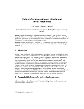
particles are clays and silts finer than 0.074 mm (#200 sieve). Well-graded soils consist ofparticles that fall into each size class, i.e. gravel, sand, silt-size, clay-size, and colloidal-size.The dashed line on Figure 2.3 represents a poorly graded soil – almost all the particles aresands finer than 4.76 mm (#4 sieve) and none of the particles are finer than 0.074 mm(#200 sieve). Poorly graded, or uniform soils typically consist primarily of particles thatfall into only one class size, such as only gravels or only sands.Figure 2.3Soil Limit States & Index PropertiesMost soils include a fine fraction of silt, clay or a combination. The consistency of thesesoils can range from a dry solid condition to a liquid form with successive addition of waterand mixing as necessary to expand pore space for acceptance of water. The consistencypasses from solid to semi-solid to plastic solid to viscous liquid as shown in Figure 2.4. A.Atterberg, a Swedish scientist, defined moisture contents representing limits dividing thestates of consistency. These limits are known as Atterberg Limits. The shrinkage limit(SL) separates solid from semisolid, the plastic limit (PL) separates semisolid from plasticstate, and the liquid limit (LL) separates plastic from liquid state. The width of the plasticstate (LL-PL), in terms of moisture content, is the plasticity index (PI). The PI is animportant indicator of the plastic behavior a soil will exhibit. The softness of a saturatedclay can be expressed numerically by the liquidity index (IL). Values of IL greater than orequal to one are indicative of a liquefaction or “quick” potential. In other words, the soilstructure may be converted into a viscous fluid when disturbed or remolded by piledriving, caisson drilling, or helical screw foundation installation. Copyright2003 Hubbell, Inc.Helical Screw Foundation System Design Manual for New Construction 2-5A.B. Chance Company
Figure 2.4Atterberg limits can be used as an indicator of stress history of a given soil. For example,if the moisture content (wn) of a saturated clay is approximately the same as the LL, thesoil is probably normally consolidated. This typically results in an empirical torque multiplier for helical screw foundations (Kt) 10. See Step 9 for a detailed description of Kt. Ifthe wn of a saturated clay is greater than the LL, the soil is on the verge of being a viscousliquid and Kt will be less than 10. If the wn of a saturated clay is close to the PL, the soil issome-to-heavily overconsolidated and Kt typically ranges between 12 and 14. If the wn of asaturated clay is intermediate (between the PL and LL), the soil is probablyoverconsolidated and Kt will be above 10. Most soils are overconsolidated, or have a history of having been loaded to a pressure higher than exists today. Some common causesare desiccation, the removal of overburden through geological erosion, or melting of overriding glacial ice.Clays lying at shallow depth and above the water table often exhibit a preconsolidationbehavior known as desiccation. They appear to be overconsolidated, but the overburdenpressure required has never existed in the soil. Desiccated clays are caused by an equivalent internal tension resulting from moisture evaporation. This is sometimes referred toas negative pore pressure. The problem with desiccated or partly dry expansive clay ispredicting the amount of potential expansion and the expansion or swell pressure – so thatpreventive measures can be taken.As water content decreases, clay particles tend to interact with one another through waterdipoles to form a microstructure. The water dipole acts to link together clay particles likeweak magnets. These bonds, along with the soil microstructure, greatly influence the 2-6A.B. Chance Company Copyright2003 Hubbell, Inc.Helical Screw Foundation System Design Manual for New Construction
shear strength of the clay. Many clays experience a temporary partial dispersion whenthey are re-molded or reworked by hand or machine. These are termed sensitive clays.Sensitivity is defined as the ratio of the strength of the soil in the undisturbed state to thatof the soil in the remolded state. All clays are sensitive to some degree, but highly sensitive soils cannot be counted on for shear strength after a helical screw foundation, drilledshaft, driven pile, etc. has been passed through it. Highly sensitive soils include marineand lacustrine (lake) deposited clays. Typical values of sensitivity are shown in Table 2.2.Table 2.2Sensitivity of ClaysClay TypeDescriptive Term Sensitivity (St)1–3Overconsolidated, Low to Medium Plastic ClaysInsensitive4–8Normally consolidated, Medium Plastic Clays Medium Sensitivity10 – 80Marine ClaysHighly SensitiveEngineering Soil ClassificationThe engineering soil classification that has gained common use is the UnifiedClassification. This system is an outgrowth of the Airfield Classification developed by Dr.A. Casagrande and has over the years been adopted by various agencies and associations.The Unified System incorporated the textural characteristics of the soil into engineeringclassification and utilizes the grain-size classification shown in Table 2.1. The basics of thesystem are shown in Table 2.4. All soils are classified into 15 groups, each group beingdesignated by two letters. These letters are abbreviations of certain soil characteristics asfollows:Table 2.3Soil CharacteristicsGSMCPtOGravelWSandNonplastic or low plasticity fines PLPlastic finesHPeat, humus, swamp soils CopyrightOrganicWell gradedPoorly gradedLow liquid limitHigh liquid limit2003 Hubbell, Inc.Helical Screw Foundation System Design Manual for New Construction 2-7A.B. Chance Company
Table 2.4ASTM (Unified) Soil Classification SystemMajor DivisionsGravels –50% or moreof coarsefractionretained on#4 sieveCoarseGrainedSoils –More than50% retainedSands –on #200 sieve*50% or moreof coarsefractionpasses#4 sieveGroupTypical DescriptionsSymbolsGWWell-graded gravels and gravel-sandCleanmixtures, little or no finesGravelsPoorly graded gravels and gravel-sandGPmixtures, little or no finesGMSilty gravels, gravel-sand-silt mixturesGravelswithGCClayey gravels, gravel-sand-clayFinesmixturesWell-graded sands, and gravelly sands,SWCleanlittle or no finesSandsPoorly graded sands and gravelly sands,SPlittle or no finesSMSilty sands, sand-silt mixturesSandwithSCClayey sands, sand-clay mixturesFinesInorganic silts, very fine sands, rockflour, silty or clayey fine sandsSilts and Clays –CLInorganic clays of low to mediumLiquid Limitplasticity, gravelly clays, sandy clays,less than 50Finesilty clays, lean claysGrainedOLOrganic silts and organic silty clays ofSoils –low plasticity50% or moreMHInorganic silts, micaceous or diatomapasses #200ceous fine sands or silts, elastic siltsSilts and Clays –sieve*CHInorganic clays of high plasticity, fatLiquid Limitclays50 or moreOHOrganic clays of medium to highplasticityPtPeat, muck, and other highly organicHighly Organic Soilssoils*Based on the material passing the 3" (76 mm) sieve.MLGW and SW groups comprise well-graded gravely and sandy soils that contain less than5% of non-plastic fines passing the #200 sieve. GP and SP groups comprise poorly gradedgravels and sands containing less than 5% of nonplastic fines. GM and SM groupsgenerally include gravels or sands that contain more than 12% of fines having little or noplasticity. GC and SC groups comprise gravelly or sandy soils with more than 12% of fines,which exhibit either low or high plasticity. ML and MH groups include the predominatelysilty materials and micaceous or diatomaceous soils. An arbitrary division between thetwo groups is where the liquid limit is 50. CL and CH groups comprise clays with low andhigh liquid limits, respectively. They are primarily inorganic clays. Low plasticity clays 2-8A.B. Chance Company Copyright2003 Hubbell, Inc.Helical Screw Foundation System Design Manual for New Construction
are classified as CL and are usually lean clays, sandy clays, or silty clays. Mediumplasticity and high plasticity clays are classified as CH. OL and OH groups arecharacterized by the presence of organic matter, including organic silts and clays. The Ptgroup is highly organic soils that are very compressible and have undesirable constructioncharacteristics. Peat, humus, and swamp soils with a highly organic texture are typical.Soil fractions are typically associated with keywords to help describe the percentage of soilcomponents. Table 2.5 relates descriptive keywords with percentage ranges.Table 2.5Soil FractionsDescriptionTraceLittleSomeAndPercentage1 - 1010 – 2020 – 3535 - 50Final classification of a soil in the Unified System will require laboratory tests todetermine the critical properties, but a tentative field classification can often be used, butconsiderable skill and experience are required. Soil boring logs often include theengineering classification of soils as described herein.Effective Stress and Pore Water PressureThe total stress within a mass of soil at any point below a water table is equal to the sumof two components, which are known as effective stress and pore water pressure. Effectivestress is defined as the total force on a cross section of a soil mass which is transmittedfrom grain to grain of the soil, divided by the area of the cross section, including both solidparticles and void spaces. It sometimes is referred to as intergranular stress. Pore waterpressure is defined as the unit stress carried by the water in the soil pores in a crosssection. Effective stress governs soil behavior and can be expressed as:σ' σ - uWhere:(Equation 2.1)σ' the effective stress in the soilσ total (or applied) stressu pore water pressureSoil StrengthOne of the most important engineering properties of soil is its shearing strength, or itsability to resist sliding along internal surfaces within a given mass. Shear strength is theproperty that materially influences the bearing capacity of a foundation soil. The basicprinciple is similar in many respects to an object resting on a table. For example, imaginea brick resting on a table top as shown in Figure 2.5. The brick is in equilibrium under itsown weight and the equal and opposite reaction force is provided by the table. Nowimagine a horizontal force is applied to the brick near the tabletop. If this horizontal forceis small, the brick will remain at rest, and the applied horizontal force will be balanced byan equal and opposite force. This resisting force is developed as a result of the roughnesscharacteristics of the bottom of the brick and the table surface. If the applied horizontalforce is gradually increased, the resisting force will also increase, always being equal inmagnitude to the applied force. When the applied force equals or exceeds the resistance,the brick will slide across the tabletop. The slippage is a shear failure. The applied Copyright2003 Hubbell, Inc.Helical Screw Foundation System Design Manual for New Construction 2-9A.B. Chance Company
horizontal force is a shearing force and the developedforce is shear resistance.The shear strength is the maximum shear resistancethat the materials are capable of developing. Shearstrength consists of two parts. The first part is thefriction between particles (physical property). Thesecond part is called cohesion, or no-load shear strengthdue to a chemical bond between particles.Figure 2.5Friction on Horizontal SurfaceSpangler (1982)Angle of Internal FrictionThe shear strength of a granular soil, such as sands,gravels and some silts, is closely analogous to thefrictional resistance of solids in contact, as describedabove and shown in Figure 2.5. The relationshipbetween the normal stress acting on a plane in the soiland its shearing strength can be expressed by thefollowing equation, in terms of stress:τf σtanφWhere:(Equation 2.2)τf the shearing stress at failure, orthe shear strengthσ normal stress acting on thefailure planeφ friction angleThe internal friction of a given soil mass is related to thesliding friction between individual soil grains and theinterlocking of soil particles. Shear strengthattributable to friction requires a normal force (σ), andthe soil material must exhibit friction characteristics,such as multiple contact areas. In dense soils, theindividual soil grains can interlock, much like the teethof two highly irregular gears. For sliding to occur, the.individual grainsmust be lifted over one anotheragainst the normal stress (σ). Therefore, the force required to overcome particle interlockis proportional to the normal stress, just the same as sliding friction is proportional tonormal stress. In soil mechanics, φ is designated the angle of internal friction, because itrepresents the sum of sliding friction plus interlocking. The angle of internal friction (φ) isa function of density, roundness or angularity, and particle size.CohesionWhen a saturated clay is consolidated, that is, when the volume of voids decreases as aresult of water being squeezed out of the pores, the shear strength increases with normalstress. If the shear strength of clays which have a previous history of consolidation (i.e.preconsolidated) is measured, the relationship between shear strength and normal stressis no longer a line intersecting the ordinate at zero. The clays exhibit a memory, orcohesive shear strength. In other words, the clays remember the preconsolidationpressure they were previously subjected to. This means considerable shear strength isretained by the soil. Figure 2.6 is an example of the relationship between shear strength 2-10A.B. Chance Company Copyright2003 Hubbell, Inc.Helical Screw Foundation System Design Manual for New Construction
and normal stress for apreconsolidated plastic clay asderived from a triaxial sheartest. The intersection of theline at the ordinate is called thecohesion.Figure 2.6Mohr’s diagram for moderately plastic soilPortland Cement Association (1992)Cohesion is analogous to twosheets of flypaper with theirsticky sides in contact.Considerable force is requiredto slide one over the other, eventhough no normal stress isapplied. Cohesion is themolecular bonding or attractionbetween soil particles. It is afunction of clay mineralogy,moisture content, particleorientation (soil structure), anddensity. Cohesion is associatedwith fine grain materials suchas clays and some silts.Coulomb Equation for Shear StrengthThe equation for shear strength as a linear function of total stress is called the Coulombequation because it was first proposed by C.A. Coulomb in 1773.τf c σtanφ(Equation 2.3)In terms of effective stress:τf c (σ - u)tanφwhere:(Equation 2.4)τf shear strengthc cohesionσ total stress acting on the failure planeφ friction angleu pore water pressureEquations 2.3 and 2.4 are two of the most widely used equations in geotechnicalengineering, since they approximately describe the shear strength of any soil underdrained conditions. They are the basis for the bearing capacity equations (4.1 and 4.3)presented in Step 4.Determination of Soil ParametersTo this point, various definitions, identification properties, limit states, engineeringclassifications, and soil strength properties have been discussed. This section details someof the more common soil exploration methods used to determine these various soilparameters. The extent to which a soil exploration program should reach depends on themagnitude of the project. If the proposed construction program involves only a smallexpenditure, the designer cannot afford to include more in the investigation than a smallnumber of exploratory borings or test pits and a few classification tests on representative Copyright2003 Hubbell, Inc.Helical Screw Foundation System Design Manual for New Construction 2-11A.B. Chance Company
soil samples. The lack of information about subsoil conditions must be compensated for byusing a liberal factor of safety. However, if a large-scale construction operation is to becarried out under similar soil conditions, the cost of a thorough and elaborate subsoilinvestigation is usually small compared to the savings that can be realized by utilizing theresults in design and construction, or compared to the expense that would arise from afailure due to erroneous design assumptions. The designer must be familiar with the toolsand processes available for exploring the soil, and with the methods for analyzing theresults of laboratory and field tests.The first step in any subsoil exploration should be an investigation of the generalgeological character of the site. The more clearly the geology is understood, the moreefficiently can the soil exploration be carried out. The second step is to make exploratorydrill holes or test pits that furnish more specific information regarding the generalcharacter and thickness of the individual soil strata. These two steps are recommendedminimums. Other steps depend on the size of the project and the character of the soilprofile.DrillingDrilling is typically the cheapest and most expedient procedure for making borings. Typesof borings are wash borings, rotary drilling and auger drilling. Any one of the three can beused, but auger drilling is the most common – particularly for shallow borings. Washborings and rotary drilling are similar in that they both use casing to hold the boreholeopen and a fluid medium to bring cuttings to the surface. The casing is either drivenwith a hammer or rotated mechanically while the hole is being advanced. The cutting bitand drill rods are inserted inside the casing and are rotated manually or mechanically.The cuttings allow the driller to visually classify the soil as to its type and condition andrecord the data on a log sheet at the depth of the cutting bit. Wash borings typically usewater whereas rotary drilling typically uses drilling mud such as bentonite slurry. Insome soil profiles, drilling
Soil mechanics is the branch of mechanics that deals with the action of forces on soil masses. The soil that occurs at or near the surface of the earth is one of the most widely encountered materials in civil, structural and architectural engineering. Soil ranks high in degree of importance when compared to the numerous