Transcription
CATALOGSEISMIC BRACING SYSTEMS,OAD 3PECIlCATIONS s (ORIZONTAL ,OAD 3CHEDULES s ESIGN 4ABLESBracing Channel, Fittings & Accessory ImagesA PART OF
TABLE OF CONTENTSIntroduction.iGeneral Information . 1-1Glossary of Terms . 1-3Brace Location Requirements. 1-4Design Procedures for Trapeze Hangers . 2-1Design Procedures for Single Pipe Hangers . 2-6Rigid & Cable Brace Factors . 2-7Seismic Table Procedure . 2-8Single Pipe Seismic Table . 2-9Trapeze Seismic Table . 2-10Trapeze Load Data . 3-1Trapeze Pipe Clamps. 3-3Single Pipe Clamps and Bracing . 3-5Hanger Rod Stiffeners/Bracing . 3-10Channel Styles . 4-1Channel Load Tables. 4-4Channel Nuts and Hardware. 4-5Brace & Cable Design Loads. 4-6Channel Fittings . 4-7Seismic Pivot Fittings (SPF) . 4-8Structure Attachments . 5-1Typical Attachments . 5-7Concrete Inserts . 5-8Anchor Load Table and Test Procedure . 6-1Design Examples . 7-1Reference . 8-1
INTRODUCTION UNISTRUT Seismic Bracing Systems are designed and constructed to resist virtually all code specified seismicforces in the event of an earthquake; therefore, keeping non-building structural components of hospitals and otheressential facilities operational and intact.Essential facilities are those structures, which are necessary for emergency post-earthquake operations. Suchfacilities shall include, but not be limited to: Hospitals and other medical facilities having surgery of emergencytreatment areas; fire and police stations; municipal government disaster operation and communication centersdeemed to be vital in emergencies.Actual applications may vary and are not limited to support methods shown. However, any changes to thesupport methods, hardware and designs depicted in these guidelines should only be made in accordance withstandard engineering practices by a qualified registered engineer and shall be approved by California Office ofStatewide Health Planning and Development (OSHPD) or governing agency.UNISTRUT bracing systems designed per the catalog requirements do not guarantee adequacy ofexisting structures to withstand the loads induced by the seismic attachments. It is the responsibility ofthe project engineer to verify that the structure is capable of supporting any and all items constructed using theseguidelines. It is the responsibility of the project engineer and the installer to determine the adequacy of placementand installation in regards to these guidelines including compliance with all applicable codes.Seismic bracing shall not limit the expansion and contraction of systems; the engineer of record shall ascertainthat consideration is given to the individual dynamic and thermal properties of these systems and the buildingstructure. Proper seismic & thermal joints should be provided as directed by the project engineer. The detailsand schedules presented do not include the weights from branch lines. All fire sprinkler branch line bracingshall comply with the requirements of the current edition of the NFPA-13. The project engineer must verify theadditional load from branch lines are within the allowable capacity of the bracing details.Where possible, pipes and conduit and their connections shall be constructed of ductile materials [copper, ductileiron, steel or aluminum and brazed or welded connection]. Pipes and their connections, constructed of othermaterial, e.g. cast iron and no-hub pipe, shall have the brace spacing reduced to one-half of the spacing forductile pipe.Pipes, ducts and conduit supported by a trapeze where none of those elements would individually be braced neednot be braced if connections to the pipe/conduit/ductwork and directional changes do not restrict the movement ofthe trapeze. If this flexibility is not provided, bracing will be required when the aggregate weight of the pipes andconduits exceed 10 lb/ft.UNISTRUT 35660 Clinton StreetWayne, Michigan 48184PH: (800) 521-7730FAX: (734) 721-4106JOSEPH L. LA BRIEStructural EngineerNo. SE 356655 E. Walnut St. Suite 277Arcadia, CA 91006DATE:PAGE04/25/2003i
GENERAL INFORMATION1. These guidelines are intended to provide information for the seismic restraint of nonstructural componentsin buildings based on the State of California Code of Regulations (CCR), Title 24. Material contained in thispublication can be referenced in the 2001 California Building Code (CBC) based on the 1997 Uniform BuildingCode (UBC). Nonstructural components may include hospital piping, electrical conduit, cable trays, and airhandling ducts. Anyone making use of the data does so at his own risk and assumes any and all liabilityresulting from such use. UNISTRUT disclaims any and all express or implied warranties of fitness for anygeneral or particular application.2. Seismic horizontal force factor:FH a pCa IpRpFH (C s )Wp( )1 3hxWphrEqn. 2 - 1Eqn. 2 - 2FH Limited by : 0.7C a I p Wp FH 4C a I p WpEqn. 2 - 3Factoring from Strength Design (FH) to Working Stress (Fh) is necessary for Seismic Force to be used in thiscatalog. Use the following formula: Fh FH/1.4.The following Seismic Design Coefficient Graph is only applicable when all of the project’s seismiccoefficients/factors (e.g. ap, Ca, etc.) are the same as those stated below. Otherwise use Eqn. 2-1 and 2-3 andreference the 2001 CBC.ap 1.0Component Amplification FactorCa 0.66Seismic CoefficientIp 1.50Seismic Importance FactorRp 3.0Component Response Modification Factorhx equipment attachment elevation with respect to gradehr structure roof elevation with respect to gradeCs Seismic Design Coefficient (Graph 1 Below) FH/Wp OLPLWV &s 0.80.911.11.21.31.4C s coefficientGraph 1: SEISMIC DESIGN COEFFICIENTUNISTRUT 35660 Clinton StreetWayne, Michigan 48184PH: (800) 521-7730FAX: (734) 721-4106JOSEPH L. LA BRIEStructural EngineerNo. SE 356655 E. Walnut St. Suite 277Arcadia, CA 91006DATE:PAGE04/25/20031-1
GENERAL INFORMATION 3. When supporting pressure piping, spacing of seismic bracing should not exceed two (2) times the verticalsupport spacing. Stress in the pipes that are comparable to those required by ASME B31.1 will be maintained.4. The CCR, Part 2, Title 24, Section 16 states the following:Where possible, pipes, conduit, and their connections shall be constructed of ductile materials (copper,ductile iron, steel or aluminum and brazed or welded connections). Pipes, conduits, and their connections,constructed of nonductile materials (e.g., cast iron, no-hub pipe and plastic), shall have the brace spacingreduced to one-half of the spacing allowed for ductile pipe.Seismic restraints may be omitted from the following installations:a. Fuel piping less than one (1) inch inside diameter.b. All other piping less than 2.5 inches diameter, except medical gas including vacuum piping, orc. All piping suspended by individual hangers twelve (12) inches or less in length from the top of pipe to thebottom of the structural support for the hanger, ord. All electrical conduit less than 2.5 inches trade size.e. All rectangular air handling ducts less than six (6) square feet in cross-sectional area, orf. All round air-handling ducts less than 28 inches in diameter, org. All ducts suspended by hangers 12 inches or less in length from the top of the duct to the bottom of thestructural support for the hanger, where the hangers are detailed to avoid bending of the hangers andtheir connection.Where lateral restraints are omitted, the piping, ducts or conduit shall be installed such that lateral motion ofthe piping or duct will not cause damaging impact with other systems of structural members, or loss of verticalsupport.5. UNISTRUT nuts and bolts mounted to UNISTRUT channels shall be tightened to the following minimumtorques:Bolt Diameter (in) Bolt Torque (ft-lbs)Bolt Diameter (in)Bolt Torque (ft-lbs)1» 41» 26505» 16511»81003» 83» 4191256. The charts and information presented on the following pages are intended as a guide only. Prior toinstallation, the user and/or engineer of record shall determine structural adequacy of supports and thesupporting structure and shall also determine compliance with applicable codes.A copy of this Seismic Bracing catalog showing the proper Seismic Brace tables and Brace LocationRequirements (Page C3) along with the UNISTRUT Engineering catalog shall be on the jobsite prior tostarting the installation of the seismic bracing system. The Seismic Tables defined in Pages 2-8 & 2-9are for a seismic factor of 1.0g and can be used to determine brace location, sizes, and anchorage ofpipe/duct/conduit and trapeze supports. The development of a new seismic table is required for seismicfactors other than 1.0g and must be reviewed by OSHPD prior to seismic bracing. For OSHPD, thesedocuments can be considered a change order in accordance with Part1, Title 24, CBC.UNISTRUT 35660 Clinton StreetWayne, Michigan 48184PH: (800) 521-7730FAX: (734) 721-4106JOSEPH L. LA BRIEStructural EngineerNo. SE 356655 E. Walnut St. Suite 277Arcadia, CA 91006DATE:PAGE04/25/20031-2
GLOSSARY OF TERMSGrade – Ground level of building; referred to as 0 ftelevation.Run – Direction of pipe layout, along the axis of thepipe.Lateral Brace – A generic term used to describe abrace that resist lateral forces in the longitudinal ortransverse direction;Strength Design – For load and resistance factordesign; ultimate load (design for most critical effectsof loads)Lateral Force – Force acting on a component orelement that is positioned across, perpendicular,or at a 90 angle to its vertical, in the horizontaldirection.Sway Brace – A mechanical device used forresisting lateral forces.Longitudinal– Direction along the horizontal axis ofa component or element’s run.Shallow Anchors – Anchors with an embeddedlength to diameter ratio of less than 8.SPF (Seismic Pivot Fitting) – A retro-fittable bracefitting used with strut or wire. Series SPF fittings area trademark of Lord & Sons, Inc.Transverse– Direction perpendicular to thehorizontal of a component or element’s run.Trapeze – Part of an assembly used to help resistseismic forces.Working Stress – Allowable load used for design;factors down strength design loads, providing asafety factor. Generally, strength design forces/1.4.UNISTRUT 35660 Clinton StreetWayne, Michigan 48184PH: (800) 521-7730FAX: (734) 721-4106JOSEPH L. LA BRIEStructural EngineerNo. SE 356655 E. Walnut St. Suite 277Arcadia, CA 91006DATE:PAGE04/25/20031-3
BRACE LOCATION REQUIREMENTS NOTE:1. THIS BRACING DETAIL APPLIES ONLY FOR COLD WATER PIPEAND GAS PIPE WHERE MOVEMENT OF THE PIPE DUE TOTEMPERATURE DIFFERENTIAL IS NEGLIBLE.2. IT IS THE RESPONSIBILITY OF THE USER OF THIS GUIDELINETO ASCERTAIN THAT AN ADEQUATE BRACING AND ANCHORAGEDEVICE BE DESIGNED FOR PIPE WHENEVER THE MOVEMENTDUE TO THERMAL DIFERENTIAL AND SEISMIC JOINT OFBUILDING EXISTS.LEGENDT TRANSVERSE BRACEL LONGITUDINAL BRACEV1 LESS THAN 24" OFFSET VERTICALLYV2 MORE THAN 24" OFFSET VERTICALLYH1 LESS THAN 24" OFFSET HORIZONTALLYH2 MORE THAN 24" OFFSET HORIZONTALLY3. TRANSVERSE BRACES FOR ONE RUN CAN BE USED ASLONGITUDINAL BRACES FOR AN ADJACENT RUN WHERETHE RUN OFFSET IS LESS THAN OR EQUAL TO 24"4. TRANSVERSE BRACES FOR ONE RUN CAN BE USED ASTRANSVERSE BRACES FOR AN ADJACENT RUN WHERETHE RUN OFFSET IS LESS THAN OR EQUAL TO 24"5. VERTICAL RUNS MUST HAVE TRANSVERSE BRACING INEACH DIRECTION AT BOTH ENDS.6. TRANSVERSE BRACE SPACING SHALL IN NO CASE EXCEEDTHE MAXIMUM CALCULATED DISTANCE OF 40ft.(QUALIFIED CALCULATIONS REQUIRED)LONGITUDINAL BRACE SPACING IS TWICETRANSVERSE SPACING BUT IN NO CASESHALL THE MAXIMUM CALCULATEDDISTANCE EXCEED 80ft.(QUALIFIED CALCULATIONS REQUIRED)7. REFERENCE PG 1-5 TO ADDRESSPIPING/CONDUIT HUNG FROM STRUCTUREABOVE CONNECTING TO EQUIPMENTMOUNTED ON FLOOR BELOW.ISOMETRIC DIAGRAM OF TRANSVERESE AND LONGITUDINAL BRACE LOCATION REQUIREMENTUNISTRUT 35660 Clinton StreetWayne, Michigan 48184PH: (800) 521-7730FAX: (734) 721-4106JOSEPH L. LA BRIEStructural EngineerNo. SE 356655 E. Walnut St. Suite 277Arcadia, CA 91006DATE:PAGE04/25/20031-4
BRACE LOCATION REQUIREMENTSSEE SECTION 5 FOR CONNECTIONDETAILS TO STRUCTURE ABOVEPROVIDE LATERAL BRACEAT FINAL SUPPORT POINTBEFORE VERTICAL DROPLESS THAN24" (TYP.)FLEXIBLE CONNECTION(BY OTHERS)IF LESS THAN 6'ADD BRACEEQUIPMENTPROVIDE ADDITIONALBRACE IF NECESSARYISOLATOR OR HARDMOUNTED TO STRUCTURE(BY OTHERS)NOTE:DETAIL SHOWS PIPING/CONDUIT HUNG FROM STRUCTURE ABOVE CONNECTING TO EQUIPMENTMOUNTED ON FLOOR TO ADDRESS THE DIFFERENTIAL MOVEMENT BETWEEN STORY TO STORY.UNISTRUT 35660 Clinton StreetWayne, Michigan 48184PH: (800) 521-7730FAX: (734) 721-4106JOSEPH L. LA BRIEStructural EngineerNo. SE 356655 E. Walnut St. Suite 277Arcadia, CA 91006DATE:PAGE04/25/20031-5
DESIGN PROCEDURES FOR TRAPEZE HANGERS 1.Determine the support spacing using the smallest pipe diameter (Page 2-3, Pipe Data Table).2.Calculate the total weight of the pipes plus contents (W) on each trapeze using the following equation:(Page 2-3, Pipe Data Table)W S x (p1 p2 p3 pn)W Total weight on trapeze (lbs)pn Weight of pipe plus water (lbs/ft)S Support spacing (ft)3.Calculate horizontal seismic force (Fh). Make necessary checks and conversion as defined in Page1-1. Page 2-4, Figures 1 & 2 can be used as a reference when solving Fh.4.Determine the actual brace force (maximum at 45 ). Reference Page 2-7 for brace connection otherthan 45 .Fb Actual Fh/cos45 1.414Fh5.Select brace to be used, Rigid or Cable.Select a channel fitting from Page 4-7 to 4-9.Check brace against allowable design load (Page 4-6) and channel slip (Page 4-5).Use the lowest design load as the allowable brace force (Fb Allow.).Determine if braces are required depending on type of brace used, Rigid or Cable:6.Check compression and tension in the rod. When diagonal braces are used to stabilize trapezehangers, they will cause tension and compression forces to be added to the tension already in the rod(see Page 2-4, Figure 1or 2, or Page 2-7).a. Select threaded rod that has a tension strength that meets or exceeds the required tension (Page3-11, Capacity of Threaded Rod Table)Brace on alternate hangersBrace on every hangerTmax .5W s(2W)Tmax .5W sW(Page 2-4, Figure 1)(Page 2-4, Figure 2)b. Check compression in the selected threaded rod. If the rod is subject to compression, it mayrequire stiffener. Determine the percentage of full stress capacity on the rod using the followingequation (Page 3-10 & Page 3-11):Actual Compression LoadAllowable Compression LoadSelect clip spacing (L) based on percentage above (Page 3-10, Channel Stiffener Table).UNISTRUT 35660 Clinton StreetWayne, Michigan 48184PH: (800) 521-7730FAX: (734) 721-4106JOSEPH L. LA BRIEStructural EngineerNo. SE 356655 E. Walnut St. Suite 277Arcadia, CA 91006DATE:PAGE04/25/20032-1
DESIGN PROCEDURES FOR TRAPEZE HANGERS7.Select pipe clamps (Pages 3-3, 3-4). Either style, P1100 Series or P2558 Series can be used.Check forces on pipe clamps using the following equations:Vertical Force Pipe Wt. per foot x Trapeze spacingTransverse Force Fh x Lateral Brace SpacingLongitudinal Force Fh x Longitudinal Brace SpacingRevise spacing of braces if necessary (not to exceed allowable design forces).8.Select trapeze member using the total weight on the trapeze and the length of trapeze required to fitthe given pipe sizes and quantities (Page 3-1, 3-2, or 4-4).9.Check trapeze member for combined vertical and lateral seismic loads using the following interactionequation: (Revise trapeze spacing or brace if necessary). Actual Vertical Force Lateral Allowable Reduction Factor Vertical Force 10. Actual Horizontal Force 1.33 Lateral Allowable Reduction Factor Horizontal Force Select concrete anchors if they are used (Page 6-1), check tension and shear interactions as perICBO reports.For shallow anchors: (Rp(3.0)/Rp(1.5))FH 2FHUNISTRUT 35660 Clinton StreetWayne, Michigan 48184PH: (800) 521-7730FAX: (734) 721-4106JOSEPH L. LA BRIEStructural EngineerNo. SE 356655 E. Walnut St. Suite 277Arcadia, CA 91006DATE:PAGE04/25/20032-2
DESIGN PROCEDURES FOR TRAPEZE HANGERS Pipe DataData for Schedule 40 Standard Weight PipePipeSize(in)Pipe SectionModulus(in)Max. Support SpacingPer ASME B31.1*, S(ft)Weight of Pipe PlusWater, Plbs/ft1» 20.0416**0.983» 40.07171.3610.13372.0511 » 20.32693.620.561105.1121 » 10**31.51816.80010**50.29*ASME B31.1 does not list all sizes shown, therefore some sizes have been proportioned between.**Spacing limited by CPC 2001.For gas pipe and copper pipe see CPC 2001 & CBC 2001 for support spacing.UNISTRUT 35660 Clinton StreetWayne, Michigan 48184PH: (800) 521-7730FAX: (734) 721-4106JOSEPH L. LA BRIEStructural EngineerNo. SE 356655 E. Walnut St. Suite 277Arcadia, CA 91006DATE:PAGE04/25/20032-3
DESIGN PROCEDURES FOR TRAPEZE HANGERShF4(411.RIGID BRACING ON TRAPEZEFIGURE 1: BRACE ON ALTERNATE HANGERS)0.5W0.5Fh CsW71W0.0.5W FhFhFh 2CsWFh 2CsWP1000 CHANNELTRANSVERSEBRACECsW45 *SPF 100 FITTING(FOR ALT. CONNECTIONSEE SECTION 4CHANNEL FITTINGS)45 MAX.Fh 2(CsW)P1000 CHANNELLONGITUDINALBRACEW GRAVITY LOAD PER TRAPEZEFh Cs(2W)ROD TENSION MAX. 0.5W FhROD COMPRESSION MAX 0.5W - Fh*SPF 200 FITTING(FOR ALT. CONNECTIONSEE SECTION 4CHANNEL FITTINGS)RIGID BRACING FOR TRAPEZEFIGURE 2: BRACE ON EVERY HANGERFh7(700.0.5Fh 0.5CsWFh0.5WW0.0.5W Fh35)Fh CsWFh CsW0.5CsW45 MAX.P1000 CHANNELTRANSVERSEBRACEP2815 BRACE(FOR ALT. CONNECTIONSEE SECTION 4CHANNEL FITTINGS)45 MAX.Fh CsWP1000 CHANNELLONGITUDINALBRACEW GRAVITY LOAD PER TRAPEZEFh CsWROD TENSION MAX. 0.5W FhROD COMPRESSION MAX 0.5W - FhP1843W HINGE(FOR ALT. CONNECTIONSEE SECTION 4CHANNEL FITTINGS)NOTE:1) FOR LOAD REACTIONS SHOWN ON THIS PAGE, THE PIPE OR CONDUIT LOADS ON THE TRAPEZE SHOULD BE RELATIVELYUNIFORM AND SYMMETRIC ALONG THE LENGTH OF THE MEMBER.2) SEE PAGE 1-1, SEISMIC DESIGN COEFFICIENT GRAPH, FOR Cs. USE OF THE SEISMIC DESIGN COEFFICIENT GRAPH ISONLY APPLICABLE WHEN ALL OF THE PROJECT'S SEISMIC COEFFICIENT/FACTORS ARE THE SAME AS LISTED ONPAGE 1-1, OTHERWISE USE EQN. 2-1, 2-3 AND REFER TO 2001CBC.*3) SPF FITTING IS A TRADEMARK OF LORD & SONS, Inc.UNISTRUT 35660 Clinton StreetWayne, Michigan 48184PH: (800) 521-7730FAX: (734) 721-4106JOSEPH L. LA BRIEStructural EngineerNo. SE 356655 E. Walnut St. Suite 277Arcadia, CA 91006DATE:PAGE04/25/20032-4
DESIGN PROCEDURES FOR TRAPEZE HANGERS WIRE BRACING ON TRAPEZE4-WAY SPLAYED PATTERN ON TRAPEZEFb (Kb)(1 2Fh)Fb (Kb)(1 2 Fh)FhFb (Kb)(1 2Fb (Kb)(1 2 Fh)Fh)PLAN VIEW0.5W Fh3 16 "0.5W FhWCABLE45 45 FhSPF 400 SEISMICCABLE FITTINGSIDE VIEWELEVATION VIEWWIRE BRACING ON TRAPEZESINGLE CABLE TRANSVERSE BRACE ON TRAPEZE0.5W Fh0.5W FhWFb (Kb)(Fh)Fb (Kb)(Fh)3 16 "CABLE45 FhSPF 400 SEISMICCABLE FITTINGSIDE VIEWELEVATION VIEWNOTE:1) FOR LOAD REACTIONS SHOWN ON THIS PAGE, THE PIPE OR CONDUIT LOADS ON THE TRAPEZE SHOULD BE RELATIVELYUNIFORM AND SYMMETRIC ALONG THE LENGTH OF THE MEMBER.2) REFER TO PAGE 2-7 FOR FORCE FACTORS ON BRACES AND RODS.3) SPF FITTING IS A TRADEMARK OF LORD & SONS, INC.4) ALTERNATE FITTINGS CAN BE USED. SEE SECTION 4 CHANNEL FITTINGS.UNISTRUT 35660 Clinton StreetWayne, Michigan 48184PH: (800) 521-7730FAX: (734) 721-4106JOSEPH L. LA BRIEStructural EngineerNo. SE 356655 E. Walnut St. Suite 277Arcadia, CA 91006DATE:PAGE04/25/20032-5
DESIGN PROCEDURES FOR TRAPEZE HANGERS1.Select hanger type (Pages 3-5 through 3-9) given the diameter of the pipe.2.Determine the maximum hanger spacing (Page 2-3, Pipe Data Table). Calculate the total weight of thepipe and contents using the following equation:W SxpW Total weight on hanger (lbs)p Weight of pipe plus water (lbs/ft)S Support spacing (ft)3.Calculate horizontal seismic force (FH) from the following,FH CsWRefer to Page 1-1 and Check if within limits. Convert from strength design FH to working stress Fh forvalues to be used in this catalog.4.Check brace forces (max. at 45 ) at every other hanger and select fittings from Page 4-6.Reference Page 2-7 for brace connections other than 45 .Fb Actual Fh/cos45 1.414Fh5.Select brace to be used, Rigid or Cable.Check brace against allowable design load (Page 4-6) and channel slip (Page 4-5).Select a fitting from Pages 4-7 to 4-9.The lowest allowable design load (Allowable Fh) governs.Determine if longitudinal braces are required using the following equation:Brace Spacing Allowable Fb / (1.414 Fh x hanger spacing)6.Check tension of rod (reference Page 2-7):Tmax W FyFy Ky*FhActual Compression LoadCheck compression: Allowable Compression LoadSelect clip spacing (L) based on percentage above (Page 3-10, Channel Stiffener Table)7.Verify pipe clamp capacity (use Design Table in Page 3-6)Actual Longitudinal Force Fh x Longitudinal Brace space8.Select concrete anchors if they are used (See Page 6-1), check tension and shear interactions as perICBO reports.Note: For shallow anchors: (Rp(3.0)/Rp(1.5))FH 2FHUNISTRUT 35660 Clinton StreetWayne, Michigan 48184PH: (800) 521-7730FAX: (734) 721-4106JOSEPH L. LA BRIEStructural EngineerNo. SE 356655 E. Walnut St. Suite 277Arcadia, CA 91006DATE:PAGE04/25/20032-6
RIGID & CABLE BRACE FACTORS SINGLE RIGID BRACERUNBRACEHANGER RODSRISE YXELEVATION VIEWTRAPEZETWO OPPOSING CABLE BRACESPLAN VIEWBRACE SLOPERISE RUNSLOPE FACTORSKbKxKy1 : 11 : 21.414 1.000 1.0001.118 1.000 0.5001 : 31.054 1.000 0.3331 : 41.031 1.000 0.250BRACE AXIAL FORCE: Fb Kb * Fh (Rigid Brace – Tension & Compression) Fb Kb * Fh (Cable Brace – Tension only)Kb Brace FactorFh Horizontal Seismic FactorFy Ky * FhFx Kx * FhSINGLE PIPETRAPEZE4-WAY SPLAYED PATTERNPLAN VIEWBRACE SLOPEX Y Z1 : 1 : 1SINGLE PIPEZSLOPE FACTORSKbKxKy2.000 1.000 1.000BRACE AXIAL FORCE:Fb Kb *1 2 Fh 2.000 * (1 2 Fh)Fb Fh (Tension only)Kb Brace FactorFh Horizontal Seismic FactorFy Ky * FhFx Kx * FhXTRAPEZEUNISTRUT 35660 Clinton StreetWayne, Michigan 48184PH: (800) 521-7730FAX: (734) 721-4106JOSEPH L. LA BRIEStructural EngineerNo. SE 356655 E. Walnut St. Suite 277Arcadia, CA 91006DATE:PAGE04/25/20032-7
SEISMIC TABLE PROCEDUREThe following procedures are for the Seismic Tables defined in Pages 2-9 & 2-10 with a Seismic Factor of 1.0g.The Sample Procedure in Pages 2-1 & 2-6 provides a detailed description for determining bracing of Trapeze andIndividually supported Water Filled Pipes, when variation of components or the use of seismic factors other than1.0g is required for design.STEPSPROCEDURE FOR USE OF SINGLE PIPE SEISMIC TABLE1.Determine size of pipe to be braced.2.Select type of Pipe Hanger to be used. Reference Page 3-5.3.Determine transverse and longitudinal brace location requirements. Reference Pages 1-4 & 1-5.4.From Single Pipe Seismic Table, obtain Maximum Brace Spacing, Minimum Rod Diameter, & LimitingBrace Length.5.Determine type of structure (concrete, wood, steel) and from the table select Anchorage quantity,size, & embedment (where applies).STEPSPROCEDURE FOR USE OF TRAPEZE SEISMIC TABLE1.Determine the maximum vertical load distributed uniformly on the trapeze from pipe(s) being braced.2.Knowing the pipe size(s), select the type and length of Trapeze from the Trapeze Seismic Table.3.From the table, select Maximum Transverse Brace Space and Minimum Rod Diameter.4.Determine transverse and longitudinal brace location requirements. Reference Pages 1-4 & 1-5.5.Determine type of structure (concrete, wood, steel) and from the table select Anchorage quantity,size, & embedment (where applies).UNISTRUT 35660 Clinton StreetWayne, Michigan 48184PH: (800) 521-7730FAX: (734) 721-4106JOSEPH L. LA BRIEStructural EngineerNo. SE 356655 E. Walnut St. Suite 277Arcadia, CA 91006DATE:PAGE04/25/20032-8
SINGLE PIPE SEISMIC TABLE SINGLE PIPE SEISMIC TABLESeismic Factor (not to exceed) 1.0gPipeDiameterPipeHangerType(in)Max. BraceSpacingTrans.Long.(ft)(ft)1» 2J120540803» 4J120740801J121040801 1» 2J121540582J122040411» 80442Min.Rod(in)ANCHORAGE (Reference Section 5 for anchorage details)Structural Wood Structural SteelNormal Weight Concrete Light Weight ConcreteBeamBeamQty.Dia. Embed. Qty. Dia. Embed. Thru Bolt Dia. A307 Bolt » 24 1» 815» 85 1» 811» 211» 23» 81» 25» 83» 4NOTES:1. System must be engineered for variation of components (ie: size, quantity, spacing) needed to the listed values that are outside the scopeof this table.2. Pipe (water filled), see Page 2-3 for pipe properties.3. Pipe Hanger capacity and details, see Pages 3-5 to 3-9.4. Brace location requirements, reference Page 1-4.5. Maximum support rod spacing per ASME B31.1, reference Page 2-3.6. Maximum P1000 allowable brace length is 10 ft. at maximum brace angle of 45 .7. 1» 2" bolt(s) and nut(s) required on brace connectors attached to channels in this catalog.(refer to Page 4-5 for allowable loads of nut in channel)UNISTRUT 35660 Clinton StreetWayne, Michigan 48184PH: (800) 521-7730FAX: (734) 721-4106JOSEPH L. LA BRIEStructural EngineerNo. SE 356655 E. Walnut St. Suite 277Arcadia, CA 91006DATE:PAGE04/25/20032-9
TRAPEZE SEISMIC TABLETRAPEZE SEISMIC TABLESeismic Factor (not to exceed) 1.0gMaximum Trapeze LengthsTransv.MaximumBraceVerticalP1000PS1001 P5500P5501SpaceLoadTrapeze Trapeze Trapeze Trapeze(max)(plf)9(ft)40111517401822302428, 293233, 342020374041, 44, 4548, 49, 543863853752642Min.RodDia.(ft)(in)101» 2Qty8(in)StructuralWood BeamThruDia. Embed.Dia.Bolt(Min.) (in)(in)StructuralSteel BeamA307Dia.Bolt(Qty) (in) (Qty)1» 24 1» 811» 21» 24 1» 821» 2(in)3» 45» 85» 85 1» 825» 889Dia. Embed. Qty(Min.) (in)910AnchorageLight WeightConcreteNormal WeightConcrete11» 25» 81» 24 1» 825» 85 1» 825» 85 1» 825» 85 1» 8211» 25» 8101» 21» 24 1» 811. System must be engineered for variation of components (ie: size, quantity, spacing) needed to the listed values that areoutside the scope of this table.2. Maximum vertical load (plf) simulates linear load of pipe(s) along pipe axis uniformly distributed on trapeze.3. Maximum Longitudinal Brace Space is 2x Transverse Brace Space, not to exceed 80 ft.4. Maximum Trapeze Lengths are for Uniform Load Capacities of Trapeze (see Pages 3-1, 3-2, 4-4) braced longitudinally.(When loads are concentrated at or near midspan of trapeze use 1» 2 of maximum trapeze length defined in table (min. of 2ft).5. For non-braced Trapeze: type, length, & use of smaller components can be acquired, reference Note 1.6. Maximum P1000 allowable brace length is 10 ft. for loads listed in table. (TABLE IS FOR RIGID BRACE ONLY)7. Maximum Hanger Spacing 10ft.8. 1» 2" bolt(s) and nut(s) required on brace connectors attached to channels in this catalog.9. Minimum 3,000 psi normal weight and light weight concrete slab/deck.UNISTRUT 35660 Clinton StreetWayne, Michigan 48184PH: (800) 521-7730FAX: (734) 721-4106JOSEPH L. LA BRIEStructural EngineerNo. SE 356655 E. Walnut St. Suite 277Arcadia, CA 91006DATE:PAGE04/25/20032-10
TRAPEZE LOAD DATA P1000 Longitudinal BraceP1000 LateralBrace*P1000T Rod Stiffener45 Max.P1000 or P5500 TrapezeSpanP1000TRod StiffenerP1000Long. BraceP1000 LateralBrace**FOR ALTERNATE CABLEBRACE SEE PG 2-5P1000DS TrapezeSpanP1000 Trapeze Load DataSpanP5500 Trapeze Load DataMaximum Uniform Concentrated LoadDesign Load@Center of SpanSpanM
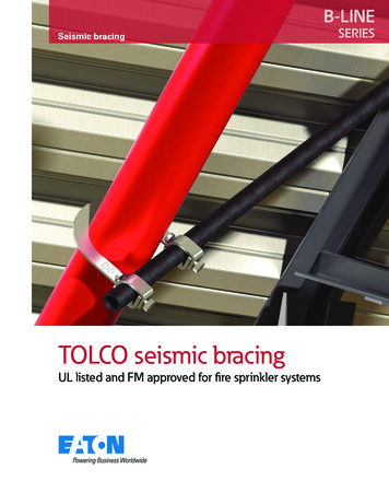
structure. Proper seismic & thermal joints should be provided as directed by the project engineer. The details and schedules presented do not include the weights from branch lines. All fire sprinkler branch line bracing shall comply with the requirements of the current edition of the NFPA-13. The project engineer must verify the