Transcription
CONSTRUCTION DETAILS AND GUIDE SPECIFICATIONS FOR INTERLOCKINGCONCRETE PAVEMENTRobert J. Burak, P.Eng.Director of EngineeringInterlocking Concrete Pavement InstituteNovember 27, 2002INFRA 2002November 25-27, 2002Hilton BonaventureMontreal, Quebec1
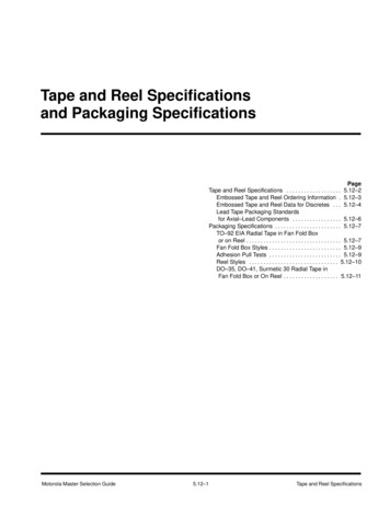
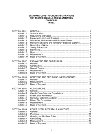
1.INTRODUCTIONThe concept of interlocking concrete pavement dates back to the Roman Empire. Even then,segmental pavements consisted of tightly fitted paving units on compacted granular base.Concrete pavers were developed in the late 1940’s in the Netherlands as a replacement for claybrick streets. By the mid 70’s automated production was introduced to North America. Today’sconcrete pavers are manufactured with highly controlled production equipment in controlledenvironments resulting in paving units with close tolerances to help ensure pavement interlock.The use of concrete pavers for municipal applications is well accepted throughout the world. InNorth America, the process of institutionalization of the concrete paver began in the mid to late80’s (Smith, 1992). While institutionalization among engineers is still in the development stagesconcrete pavers are considered an orthodox solution in many applications, particularly heavy loadapplications. In 1980, the total consumption of pavers in North America for all markets wasestimated at 40 million ft2 (4 million m2). For 2001, total sales of pavers in North America isestimated at 430 million ft2 (43 million m2). Commercial and municipal applications account forapproximately 32% of the market.The growing acceptance of concrete pavers, is due in part to acceptance overseas as well asacceptance of design methods within the North American engineering community. Internationally,over 5 billion ft2 (500 million m2) are installed annually. This paper will discuss how interlockingpavements function structurally, and how to detail, specify, and construct these pavements forsuccessful performance. Design software for structural calculations will also be discussed.2. PRINCIPLES OF DESIGN AND CONSTRUCTION OF INTERLOCKINGPAVEMENTS2.1AdvantagesInterlocking concrete pavements offer the advantages of concrete materials, but with flexibleperformance similar to asphalt pavement. As high strength concrete, the units have high resistanceto freeze-thaw cycles and de-icing salts, high abrasion and skid resistance, no damage frompetroleum products or from concentrated point loads or high temperatures. Load transfer isachieved through shear transfer through the various joints in the pavement. As with flexibleasphalt pavement, an aggregate base accommodates minor settlement, however the difference withthe interlocking pavement is that it will not crack. Another advantage to these pavements is accessto underground utilities and the ability to re-instate the paving units, thereby reducing wastematerials. The results of the life-cycle cost analysis for Main Street, North Bay, (JEGEL, 2000)indicate that when a discount rate of 4% is applied, interlocking concrete pavements are more costeffective than asphalt pavements for this type of application.2.2InterlockCritical to the structural performance of segmental concrete pavements is the concept of interlockbetween the units. Figure 1 demonstrates the three types of interlock that must be achieved;vertical, rotational, and horizontal. Vertical interlock relies primarily on shear transfer of loads toadjacent units through the jointing sand, rotational interlock relies mainly on paver thickness, unit2
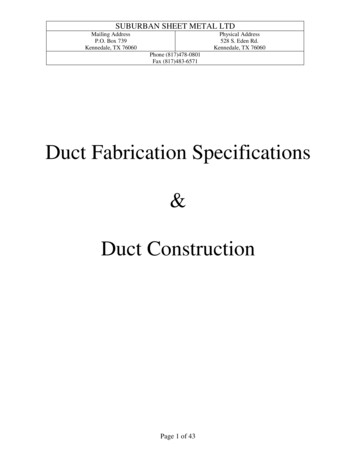
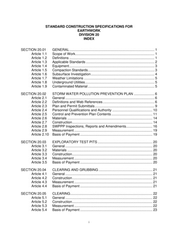
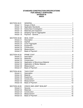
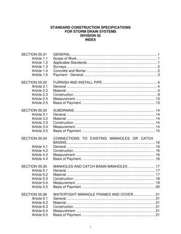
spacing, and edge restraint, and horizontal interlock relies primarily on laying patterns thatdisperse braking, turning, and accelerating forces. Figure 2 shows a herringbone pattern that isuniversally recommended for areas subjected to vehicular traffic. Testing has shown that thislaying pattern with the use of dentated (or non-rectangular) paver shapes offer the greateststructural capacity and resistance to horizontal creep (Shackel, 1979, 1980).Figure 1: The three types of interlock – vertical, rotational, and horizontalSource: Interlocking Concrete Pavement InstituteFigure 2: Recommended laying patterns for vehicular trafficSource: Interlocking Concrete Pavement Institute2.3Typical Pavement SectionsFigure 3 shows typical pavement cross sections for interlocking concrete pavements. The paversare laid on a one-inch (25 mm) thick sand bedding layer over a compacted bound or unbound baseand a granular sub base as required. The base design and sub base requirement are determined bythe severity of the applied loads and either the resulting vertical stresses and strains at the top of3
the subgrade or the horizontal strains in the base. Many pavements for city uses do not require anaggregate sub base except for very heavy use, or over a weak soil subgrade. In these situations itmay be more economical to use asphalt or cement stabilized base layers. Often, they are placedover a sub base layer of unbound compacted aggregate.The Interlocking concrete paving system also relies on the design and installation of adequaterestraint in the form of an edge restraint (ICPI, 1994). The requirement for geotextile applicationover the subgrade is dependent on the soil conditions. Geotextile may be required to facilitateencapsulation of bedding and joint sands in applications with stabilized bases.Figure 3: Typical Cross sections for interlocking concrete pavementsSource: Interlocking Concrete Pavement Institute2.4Concrete Paver SpecificationsConcrete pavers are manufactured to CSA A231.2 specifications. In this specification, concretepavers are defined by their aspect ratio (length over thickness) and by their total surface area. Aconcrete paver, by definition, must have an aspect ratio less than 4:1 and a surface area less than100.25 in2 (0.065 m2). For areas subject to constant vehicular use the required aspect ratio is lessthan 2.5:1 and is assumed for the purposes of this paper. CSA specifies a minimum averagecompressive strength of 50 Mpa (7250 psi) and includes a durability requirement of a maximumloss of 200 g/m2 of surface area after 25 cycles of freeze and thawing in a 3% saline solution or500 g/m2 loss after 50 cycles.2.5Pavement MaterialsCompaction of the soil subgrade is critical to the performance of interlocking concrete pavements.Adequate compaction will minimize settlement. For vehicular areas, compaction should be aminimum of 95% modified proctor density according to ASTM D 1157. In extremely saturated orvery fine soils stabilization of the soils may be required and geotextiles should be considered.Crushed aggregate bases, or stabilized bases used in flexible asphalt construction are generallysuitable for interlocking concrete pavement. Typically, provincial specifications fro gradation will4
be sufficient. The minimum recommended strength requirements for unbound aggregate basesshould be CBR 80% and for sub-bases, CBR 30%. Base material should have a plasticity indexno greater than 6 and a liquid limit no greater than 25. Compaction of the granular base forvehicular areas should be at least 95% of modified proctor density as determined by ASTM D1557, or AASHTO T-180 density. The final base tolerance should be checked with string lines,transit or straight edge and conform to a tolerance of /- 10 mm over 3 m.Bedding sand should be consistent throughout the pavement and not exceed 1.0 inches (25 mm)after compaction. The bedding layer acts as the resting spot for the pavers, but more importantly,facilitates initial interlock of the pavers and provides a drainage layer for water that penetratesthrough the joints. The sand should be as hard as practically available and should not be screeningmaterial or stone dust. Screening material will deteriorate after repetitive traffic loading, and bothscreenings and stone dust will not provide for adequate drainage. These materials will thenlubricate, move, and result in deformation (rutting) under loading.ICPI recommends the Liley-Dowson test to determine bedding sand hardness. One (1) 1.4 kgsample of bedding sand is randomly sampled from the sand source. The sample is dried for 24hours at 115C to 121 C. Three (3) sub samples, each weighing 0.2 kg are obtained by passing themain sample several times through a riffle box. A sieve analysis is carried out on each sub sampleaccording to ASTM C 136. Each sample is remixed and placed in a nominal liter capacityporcelain jar with two 25 mm steel ball bearings weighing 75 grams each. Each jar is rotated at 50rpm for six hours. The sieve analysis is repeated and the individual and average sieve analysis isrecorded. For each sample tested, the maximum increase in the percentages passing each sieve andthe maximum individual percent passing shall be as indicated in Table 1 below.Table 1Bedding Sand Degradation Test – Maximum Percent PassingSieve SizeNo. 200 (80µm)No. 100 (160µm)No. 50Maximum Increase2%5%5%Maximum Passing2%15%35%The CSA A23.1 (FA 1) gradation for concrete sand should be used for the bedding layer (SeeTable 2). The only exception is that there should be no allowance for fines passing the 80 µmsieve (ie. 0% passing). To facilitate bedding of the pavers, the sand should be at optimummoisture content.5
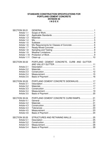
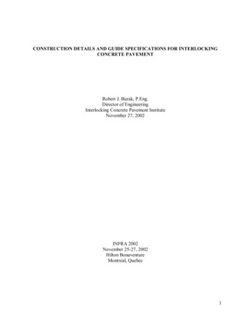
Table 2CSA A23.1 (FA 1)Gradation for Bedding SandSieve Size:10 mm5 mm2.5 mm1.25 mm630 µm315 µm160 µm% Passing10095-10080-10050-9025-6510-352-10Joint sand provides vertical interlock and shear transfer of loads. It can be slightly finer than thebedding sand. Gradation for this material can have a maximum 100% passing the 1.25 mm sieveand more than 10% passing the 80µm sieve. Commonly the bedding sand is used for the jointsand for easier control of job site materials. This will require additional effort in filling the jointsduring compaction due to the coarser gradation. Joint sand should be dry when swept in to thejoints to ensure that there is no bridging of sand in the joints, which would decrease interlock.Consideration should also be given to joint sand stabilizers, which have been shown to reduce thelong-term loss of joint sand.2.6Construction of Interlocking PavementsDue to the similarities in flexible pavement performance, the soil subgrade and base materials areprepared and installed in a similar manner to asphalt pavements. Following the installation of thebase, bedding sand is placed to a uniform thickness, typically 1 to 1-1/2 inches (25-50mm) by aprocess of hand or mechanical screeding (See Figure 4). The paver units are then placed either byhand or mechanically. Depending on the type of edge restraint used, it is installed either before theinstallation of the bedding sand or after. The pavers are then placed and vibrated into place with ahigh frequency plate vibrator with a minimum force of 22 kilo-newtons to facilitate compaction ofthe bedding sand and migration into the bottom of the joints of the pavers (See figure 5). Jointsand is then swept into the joints by hand or mechanically. The units are compacted again toensure complete filling of the joints and the necessary interlock for performance of the pavement(See figure 6).2.7Detailing and Construction TipsWell designed and constructed details increase the quality of any interlocking concrete pavement.Figure 7 shows pavers cut and placed directly against a restraint and Figure 8 shows the samedetail with a row of full pavers against the restraint. Pavers will not only look better with the latterdetail, but perform better as well. For vehicular traffic, cut pavers should be at least 1/3 of thewhole paver. In Figure 9, the cracked units on one side of the curb were cut to less than a third insize and suffered from repetitive tire loads, whereas the ones on the right did not since they werelarger.6
Figure 4: Mechanical screeding of bedding sandSource: Interlocking Concrete Pavement InstituteFigure 5: Initial compaction of concrete pavers begins the process of interlock by forcing thebedding sand to move up into the jointsSource: Interlocking Concrete Pavement Institute7
Figure 6: Joint sand is applied and the pavers go through a final compactionSource: Interlocking Concrete Pavement InstituteFigure 7: Pavers cut and placed directly against a restraintSource: Interlocking Concrete Pavement Institute8
Figure 8: A row of full pavers against the restraint gives a better visual appearance and increasesthe performance of the pavementSource: Interlocking Concrete PavementInstituteFigure 9: In this vehicular application, the pavers on the left were cut and placed at less than 1/3 ofthe original paver size, whereas the ones on the right were not.Source: Interlocking Concrete Pavement InstituteSettlement of pavers against curbs is caused by two sources. One is insufficient compaction of thesoil and the base next to the curb. After curbs are constructed, they are generally backfilled andthe compaction of the material should be monitored with a density guage. Figure 10 shows failure9
at a curb interface as the result of inadequate compaction. The other source of settlement at thecurb is the loss of bedding sand through joints in the curb (See Figure 11). This can be mitigatedby the detail and construction shown in Figures 12 and 13.Figure 10: To eliminate settlement at the edge of curbs, backfilled materials must be adequatelycompacted and the density monitored with density gaugesSource: Interlocking Concrete Pavement InstituteFigure 11: To prevent loss of bedding sand at the edge of curb, geotextile is recommendedSource: Interlocking Concrete Pavement Institute10
Figure 12: Detail for sidewalk and curb – Note the geotextile wrapping up the full height of thecurb and extending 300mm into the pavement sectionSource: Interlocking Concrete Pavement InstituteFigure 13: Geotextile shown at the interface of the curb to prevent loss of the bedding sandSource: Interlocking Concrete Pavement Institute11
Settlement and cracking of pavers against a utility access cover can be prevented by using aconcrete collar (See Figure 14). The paver pattern is
vehicular areas should be at least 95% of modified proctor density as determined by ASTM D 1557, or AASHTO T-180 density. The final base tolerance should be checked with string lines, transit or straight edge and conform to a tolerance of /- 10 mm over 3 m. Bedding sand should be consistent throughout the pavement and not exceed 1.0 inches (25 mm)