Transcription
Radar Basics
WHAT IS RADAR? . 3RADAR APPLICATIONS . 3FREQUENCY BANDS . 3CONTINUOUS WAVE AND PULSED RADAR . 4PULSED RADAR . 4PULSE POWER . 4RADAR EQUATION . 5PULSE WIDTH . 5PULSE MODULATION . 6Linear FM Chirps . 6Phase Modulation . 6Frequency Hopping . 6Digital Modulation . 6PULSE COMPRESSION. 6LIFECYCLE OF RADAR MEASUREMENT TASKS . 7CHALLENGES OF RADAR DESIGN & VERIFICATION . 7CHALLENGES OF PRODUCTION TESTING. 7SIGNAL MONITORING . 8BASIC RF PULSED RADAR SIGNALS . 8TRANSMITTER TESTS. 9RECEIVER TESTS . 9
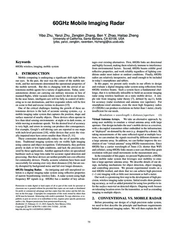
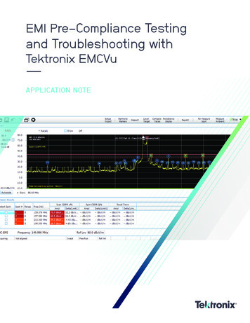
Modern radars produce complicated pulses that can presentsignificant measurement challenges. Improvements to range,resolution, and immunity to interference have motivatednumerous coding schemes, frequency and phase modulatedpulses, frequency chirped pulses, and narrow pulses with highoverall bandwidth.Frequency BandsRadar frequency bands are classified into letter designationsdefined by the IEEE (see Table 1). The most commonly usedbands used today for radar are the L-band through the KUband or 1 – 18 GHz. Short-range automotive radar systemsuse the very high W-band frequencies in the 75 GHz range.Figure 1: A Weather Radar DisplayTable 1 Common Radar Frequency BandsWhat is Radar?BandRadar (RAdio Detection And Ranging) is actually a fairlysimple process of bouncing radio waves off objects andlooking at the reflections to determining presence, size,distance, position and speed.Typically, radars illuminate their targets with an RF pulse andthen listen for the return echo. Since the RF pulse propagatesat the speed of light, the time it takes the echo to return isproportional to the distance from the target. This, of course,applies to a primary-radar, one that relies on reflected energybouncing back off the target. Secondary-radars, that retransmit the signal back from a transponder, have additionaldelays.Transmitted RF signals are “bounced” off a target and areceiver measures the characteristics of the echo. Most often,low duty cycle pulses are used.As the technology has evolved, the basic concept of radar hasnot changed. At the same time, the accuracy, resolution andnumber of radar applications has increased dramatically overtime.Radar ApplicationsRadar technology is used heavily in military applications.Ground-based radar is used for long-range threat-detectionand air traffic control. Ship-based radar provide surface-tosurface and surface-to-air observation. Airborne radar isutilized for threat detection, surveillance, mapping, andaltitude determination. Finally, missile radars are used fortracking and guidance.There are many commercial aviation applications of radarsuch as air traffic control (ATC) long range surveillance,terminal air traffic monitoring, surface movement tracking, andweather surveillance. Additionally, short-range radar isincreasingly being used in automotive applications for collisionavoidance, driver assistance, and autonomous driving.Specialized radars can also be used to provide imagingthrough fog, through walls, and even underground.UseRangeHFLong-range, over the horizon(OTH)3-30 MHzVHFLong-range, over the horizon(OTH)30-300 MHzUHFLong-range, over the horizon(OTH)300 MHz-3GHzLLong range Air Traffic Control(ATC), surveillance1-2 GHzSMedium Range, AirportSurveillance Radar (ASR),long range weather, marine radar2-4 GHzCWeather, snow/ice mapping,precipitation detection4-8 GHzXMissile guidance, marine radar,weather, ground surveillance,short-range airport tracking radar8-12 GHzKuHigh-resolution radar, satellitetransponders12-18 GHzKCloud detection, police radar18-27 GHzKaShort range, airport surveillance,red-light traffic camera trigger27-40 GHzVVery short range, spaceapplications40-75 GHzWAutomotive/vehicleparking/warning radar systems,imaging75-110GHzwww.tektronix.com/radar3
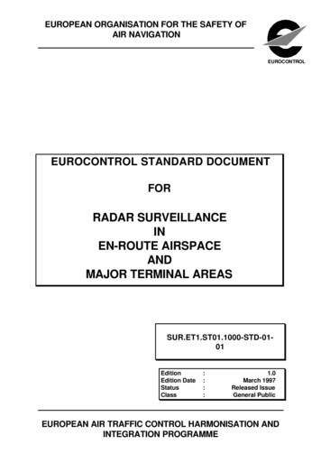
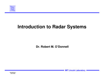
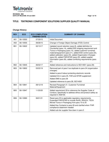
Continuous Wave and PulsedRadarRadar systems can use continuous wave (CW) signals or,more commonly, low duty-cycle pulsed signals. CW radarapplications can be simple unmodulated Doppler speedsensing systems such as those used by police and sportsrelated radars, or may employ modulation in order to senserange as well as speed. Modulated CW applications havemany specialized and military applications such as maritime /naval applications, missile homing, and radar altimeters. Thedetection range of CW radar systems is relatively short, due tothe constraints of continuous RF power. There is no minimumrange, however, which makes CW radar particularly useful forclose-in applications.Pulsed RadarThe radar measurements discussed in this document are allpulse measurements. Although there are several continuoustransmission types of radar, primarily Doppler, the greatmajority of radars are pulsed. There are two generalcategories of pulsed radar, Moving Target Indicator (MTI) andPulsed Doppler. MTI radar is a long-range, low pulserepetition frequency (PRF) radar used to detect and tracksmall ( 2m2) moving targets at long distances (up to 30km)by eliminating ground clutter (aka chaff). MTI is useful whenvelocity is not a big concern (i.e. “just tell me if something ismoving”). Pulsed Doppler radar, in contrast, utilizes a highPRF to avoid “blind speeds” and has a shorter “unambiguous”range ( 15km), high resolution, and provides detailed velocitydata. It is used for airborne missile approach tracking, airtraffic control, and medical applications (e.g. blood flowmonitoring).better resolution. This relationship constitutes one of thefundamental trade-offs in radar engineering. Pulsecompression with a modulated carrier is often used toenhance resolution while maintaining a narrow PW allowingfor higher power and longer range.The Pulse Repetition Interval (PRI) is the time the pulse cycletakes before repeating. It is equal to the reciprocal of the PRFor Pulse Repetition Rate (PRR), the number of transmittedpulses per second. PRI is important because it determines themaximum unambiguous range or distance of the radar. In fact,pulse-off time may actually be a better indication of the radarsystem's maximum design range.Traditional radar systems employ a Transmit/Receive (T/R)switch to allow the transmitter and receiver to share a singleantenna. The transmitter and receiver take turns using theantenna. The transmitter sends out pulses and during the offtime, the receiver listens for the return echo. The pulse-offtime is the period the receiver can listen for the reflected echo.The longer the off-time, the further away the target can bewithout the return delay putting the received pulse after thenext transmitted pulse. This would incorrectly make the targetappear to be reflected from a nearby object. To avoid thisambiguity, most radars simply use a pulse-off time that is longenough to make echo returns from very distant objects soweak in power, they are unlikely to be erroneously detected inthe subsequent pulse's off-time.Figure 3 illustrates the need for pulse compression to obtaingood range and resolution. Wider PWs have higher averagepower, which increases range capability. However, wide PWsmay cause echoes from closely spaced targets to overlap orrun together in the receiver, appearing as a single target.Modulated pulses mitigate these issues, providing higherpower and finer resolution to separate closely spaced targets.The RF pulse characteristics reveal a great deal about aradar's capability. Electronic Warfare (EW) and ELectroniclNTelligence (ELINT) experts specialize in the study of thesepulsed signals. Pulse characteristics provide valuableinformation about the type of radar producing a signal andwhat its source might be - sailboat, battleship, passengerplane, bomber, missile, etc.Figure 3. Pulse Width versus ResolutionPulse PowerFigure 2. Common Pulse CharacteristicsPulsed radar typically utilizes very low duty cycle RF pulses ( 10%). The range and resolution is determined by the pulserepetition frequency (PRF), pulse width (PW), and transmitpower. A wide PW generally provides better range, but poorresolution. Conversely, a narrow PW supports less range, but4 www.tektronix.com/radarAnother consideration for the maximum range of a radar is thetransmitted power. Peak power is a measure of the maximuminstantaneous power level in the pulse. Power droop, pulsetop amplitude, and overshoot are also of interest. ELINTexperts sometimes scrutinize these characteristics, as theyprovide additional information about a radar's characteristics.
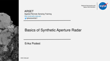
Pulse top amplitude (Power) and Pulse Width (PW) areimportant for calculating the total energy in a given pulse(Power x Time). Knowing the duty cycle and the power of agiven pulse, the average RF power transmitted can becalculated (Pulse Power x Duty Cycle).Radar EquationThe Radar Equation, as it is commonly known, defines manyof the engineering trade-offs encountered by radar designers.Equation 1. Radar Range EquationThe radar equation relates the expected receive power (Pr) tothe transmitted pulse power (Pt); based on transmit antennagain (Gt), area of the receive antenna (Ar), target cross section(aka reflectivity) σ, range from the transmitter antenna to thetarget (Rt), and range of the target to the receive antenna (Rr).airliner, or multiple smaller targets closely spaced, possibly atight formation of fighter aircraft. Without sufficient resolution,it is impossible to determine the number of objects thatactually make up the echo return. Narrow pulse widthsmitigate the overlapping of echoes and improve resolution atthe expense of transmit power.Pulse width thus affects two very important radar systemcapabilities - resolution and detection range. These twoqualities are traded off against each other. Wider pulsesequate to longer-range radars with less resolution, whereasnarrow pulses equate to finer resolution but shorter range.Narrow pulses also require greater bandwidth to correctlytransmit and receive. This makes the pulse's spectral naturealso of interest, which must be considered in the overallsystem design (see Figure 4).Unlike many communications systems, radar systems sufferfrom very large signal path losses. The round-trip distance istwice that of a typical communications link and there arelosses associated with the radar cross-section and reflectivityof targets. As can be observed from the Radar Equation, therange term is raised to the fourth power in the denominator,underscoring the tremendous signal power losses radarsignals experience. There are also several forms of the radarequation that take into account differing applications andantenna configurations.Using the radar equation, the received signal level can becalculated to determine if sufficient power exists to detect areflected radar pulse. Combining multiple pulses toaccumulate greater signal power and average out the noise isalso helpful for increasing the detection range.Figure 4. Pulse Time vs Frequency CharacteristicsPulse WidthPulse width is an important property of radar signals. Thewider a pulse, the greater the energy contained in the pulsefor a given amplitude. The greater the transmitted pulsepower, the greater the reception range capability of the radar.Greater pulse width also increases the average transmittedpower. This makes the radar transmitter work harder. Thedifference in decibels (dB) between the pulse power andaverage power level is easily calculated using ten times thelog of the pulse width divided by the pulse repetition interval.Range is therefore limited by the pulse characteristics andpropagation losses. The PRI and duty cycle set the maximumallowed time for a return echo, while the power or energytransmitted must overcome the background noise to bedetected by the receiver.Pulse width also affects a radar’s minimum resolution. Echoesfrom long pulses can overlap in time, making it impossible todetermine the nature of the target or targets. A long pulsereturn may be caused by a single large target, possibly anwww.tektronix.com/radar5
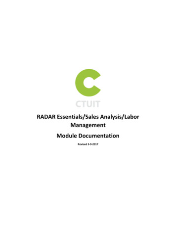
Pulse ModulationWhile unmodulated pulsed radar are relatively simple toimplement, they have drawbacks. As described previously,unmodulated pulses have relatively poor range resolution. Tomake the most efficient use of transmit power and optimizerange resolution, most radars modulate pulses using a varietyof techniques (see Figure 5).performance in the presence of Doppler effects. Additionally,the variable frequency pattern used by hopping pulsesreduces susceptance to spoofing and jamming. This alsoreduces interference between transmitters in close proximity.Digital ModulationWith the advancements of software defined radio and digitalsignal processing applied to radar, more complex pulsemodulations are now used. For example, more effective antispoofing can be accomplished using M-ary PSK or QAMmodulations. These modulations produce pulses thatresemble noise as opposed to coherent frequencies, whichmakes them harder to detect. Other information can beencoded into these more complex digital modulations as well.Pulse CompressionBasic pulsed radar using time-of-flight to measure target rangehas limitations. For a given pulse width, the range resolution islimited to the distance over which the pulse travels during thetime of its duration. When multiple targets are at nearly equaldistance from the radar, the return from the farthest target willoverlap the return from the first target. In this situation, the twotargets can no longer be resolved from each other with justsimple pulses.Figure 5. Common Pulse Modulations – constant CW (top),Linear FM (middle), Phase-Shift Keying (bottom)Linear FM ChirpsThe simplest pulse modulation scheme is the linear FM (LFM)chirp. It is also the most common types of pulse compressionand is in wide use. Sweeping the carrier frequency throughouta pulse results in every part of a pulse being distinct anddiscernable. This enables pulse compression techniques to beutilized in the receiver, which is a very powerful radartechnique for improving range resolution and making moreefficient use of transmit power.Phase ModulationUsing a short pulse width is one way to improve distanceresolution. However, shorter pulses contain proportionately lessenergy, preventing reception at greater range due topropagation losses. Increasing the transmit power is impracticalin many cases, such as for aircraft radar due to power constraints.The answer to these challenges is the use of pulsecompression. If a pulse can be effectively compressed in time,then the returns will no longer overlap. Pulse compressionallows low amplitude returns to be “pulled” out of the noisefloor. It is achieved by modulating the pulse in the transmitterso different parts of the pulse become more discernable. Theactual time compression is accomplished by the radarreceiver.Phase modulation can also be used to differentiate segmentsof a pulse in a similar fashion as frequency hopping. Pulsephase modulation is often implemented as a version of BinaryPhase-Shift Keying (BPSK). There are specific phase codingschemes, such as Barker Codes to ensure orthogonality of thecoding while providing excellent range resolution.Frequency HoppingAnother modulation technique utilizes several frequency hopswithin a pulse. If each frequency has a corresponding filterwith the appropriate delay in the receiver, then all segmentscan be compressed together in the receiver. If the frequencyhopping sequence remains the same for all pulses, then thereceiver compression can even be implemented with a simpleSurface Acoustic Wave (SAW) filter. One common form offrequency hopped coding is known as Costas Coding. This isa coding that intentionally reduces the side-lobes in theperiodic auto-correlation function and has advantageous6 www.tektronix.com/radarFigure 6. A matched filter in the receiver compresses thesignal in timeThe most common pulse compression technique linearfrequency modulation, or LFM pulses. A LFM pulse is onewhere the pulse begins at one carrier frequency, then rampslinearly, up or down to an end frequency. LFM pulses areoften called “chirps” or chirped pulses. Compression isachieved in the receiver by passing the signal through amatched filter (see Figure 6). This filter is designed to have adelay characteristic matched to the LFM frequency range, and
delays portions of the modulated signal proportional to thecarrier frequency. For example, the filter may delay thestarting frequency of the LFM more than the ending frequencyof the LFM, causing the leading edge of the pulse to bedelayed more than the trailing edge. When the pulse passesthrough a receiver signal processor, the chirp will transformfrom a frequency chirp pulse to a narrow pulse containing allthe frequencies overlapped. The width of the resulting pulse isdependent on the frequency resolution of the receiverprocessor. Bear in mind, there will be additional time-smearingand ringing due to non-linearity in the transmitted pulse.When a pulse entering the receiver is a target return, there willlikely be multiple close reflections due to the different surfacesof the target. If the compression signal processor hassufficient resolution, it can separate each of these reflectionsinto discrete narrow pulses.Figure 7. Barker coded binary phase shift keying (BPSK)Another common pulse compression technique employsbinary phase shift keying, or BPSK modulation, using a Barkercoded sequence (see Figure 7). Barker codes are uniquebinary patterns that auto correlate against themselves at onlyone point in time. Barker Codes can vary in length from 2 - 13bits, providing a corresponding compression ratio of 2 - 13.The compression is achieved in the receiver by sensing theauto-correlation of the Barker sequence within the detectedpulse.Figure 8. Barker coded spectrum showing side-lobesuppressionLifecycle of RadarMeasurement TasksThe measurements needed for radar will vary depending onthe job to be done and the type or radar to be characterized.From radar system design and component selection to thesurveillance of deployed radars, accurate and fastmeasurements are required with reproducible results.Challenges of Radar Design &VerificationWhen performing radar design verification, there is a need toassure the transmitted signal is correct, the receiver respondsto and detects the correct signals, and that there are nospurious signals emitted from the transmitter. Unexpectedoutputs can range from unintended signals related to thedesired pulse (such as harmonics, sub-harmonics, imagemixing products, etc.), as well as spurious outputs unrelated tothe desired pulse, such as radiation of internal localoscillators, coupling from digital clocks, spurious oscillationswithin RF circuitry, pulse errors, and so forthIn the modern world of "software defined" radar, modulatedpulses, chirps, and other waveforms are usually not generatedwith traditional analog circuitry, but with Digital SignalProcessors (DSP) and Direct Digital Synthesis (DDS)techniques. These digital techniques generate complicatedsignals directly at intermediate frequencies (IF) or RFfrequencies. The signals only become analog when thesynthesized digital data is passed through a digital-to-analog(D/A) converter.Within the DSP, subtle software code and numeric errors suchas poorly chosen filter constants, numeric rounding, oroverflow errors can create very short-duration artifacts thatmay bear little or no relation to the desired output. A singleDSP error can create momentarily incorrect RF output (i.e. aglitch). This can play havoc when filtered, amplified, andtransmitted.Spurious emissions can also interfere with other RF servicesin the deployment area and often provide a distinctivesignature if they are specific to a particular transmitter design.Wideband radars can also “bleed” into surrounding spectrumcausing unintended interference well outside the assignedspectrum.Challenges of Production TestingProduction testing involves verification that eachmanufactured product meets its specifications. Test tasksinclude tuning and calibrating assemblies, along with thecompensation and calibration of analog modules, linearizers,and amplifier components. Results must be accurate andrepeatable to assure the final product will function asintended. As component and subsystem vendors makechanges to their processes, continued verification ofwww.tektronix.com/radar7
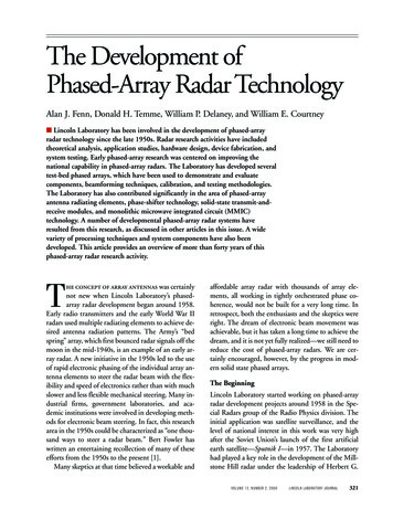
performance is required without varying the tests throughoutthe product lifecycle.Automated testing reduces the chance for operator error,which is a drawback of manual test processes and manuallyoperated test equipment. With automation, reproducibility oftest results can be maintained regardless of productionpersonnel changes and training requirements can besignificantly reduced.Signal MonitoringSignal monitoring is a different challenge. For SignalMonitoring, there is less need to verify a specification, butmore to identify signals that may be present in the surroundingarea or show themselves only very rarely. These types ofinterfering signals can jam or reduce the effectiveness of aradar. When searching for pulsed or interfering signals, an RFanalyzer must not “blink” when the signal appears.Discovering, triggering, and capturing infrequent signals ortransient characteristics of signals are required beforeanalysis can be performed.Interference may be manifested not only as an infrequentproblem, but may be an issue of multiple signals contendingfor the same spectrum, either intentionally or unintentionally.Discovering such overlapping signals can be very difficultusing traditional test equipment.Figure 9. Oscilloscope trace of an RF pulse trainBasic RF Pulsed Radar SignalsA simple pulse can be a single frequency that is turned on fora short time and then off again. The signal travels from thetransmit antenna, reflects off of a target and returns to theradar. The time it takes for the pulse to return represents therange, or distance to the target.An oscilloscope can show the time domain voltage waveformof the transmitted pulse. This includes all individual cycles ofthe RF pulse as in Figure 9.A RF detector can be used to create a trace of the envelope ofthe pulse, instead of the individual cycles. This makestriggering much easier. A Vector Signal Analyzer (VSA), or aspectrum analyzer in zero-span, can display amplitude versustime. This is the equivalent of using a RF detector. The lowertrace in Figure 10 is a spectrum analyzer detected envelope ofa single RF pulse seen in the voltage waveform of Figure 9.A spectrum analyzer can also show the frequency spectrum ofthe pulse. The sin(x) / x (pronounced "sine x over x") classicpulse spectrum plot is seen in the upper trace. A VSA can usea Fast Fourier Transform (FFT), or other Discrete-TimeFrequency Transformation (DTFT), to make such a spectrumplot of a single pulse. A swept spectrum analyzer must eitherbe in a "maximum trace hold" mode, or it must sweep slowlyenough that at least one pulse appears at each positionacross the screen to provide a complete spectrum view.Without additional frequency processing software, theoscilloscope provides only the voltage waveform.8 www.tektronix.com/radar
Figure 10. RF pulse spectrum (top) and pulse trace (bottom)Transmitter TestsModern radars often generate pulses at an IntermediateFrequency (IF) where the processing is easier and thenconvert the IF frequency to the final CW frequency beforeamplifying it to the necessary high power. When testing an upconverter from the IF system, or testing the power amplifier, aradar pulse generator is needed in addition to the pulseanalyzer.There are several solutions available for generating radarpulses. Arbitrary Function Generators (AFGs), ArbitraryWaveform Generators (AWGs), and software to create thenecessary pulses can generate baseband, IF, RF, ormicrowave signals using direct synthesis up to 10 GHz andhigher. Test waveforms can be imported into the generators,synthesized, and replayed. Signal generation is often requiredin the selection and verification of analog transmittercomponents to test the margin of design and manufacturingprocesses.Receiver TestsTesting the receiver portion of a radar system, when thecompanion transmitter is not yet available, requires pulsegeneration equipment. However, verification of receiverperformance under varying signal conditions may not bepossible using the companion transmitter. This requires agenerator with the capability to add impairments anddistortions to generated pulses. Common impairments are inchannel and out-of-channel signals and noise to testdesensitization or blocking. This will verify the limits of receiverfunctionality. A generator of waveforms with arbitrary variationof any part of a digitally created waveform fills this need.www.tektronix.com/radar9
Contact Information:ASEAN / Australia (65) 6356 3900Austria 00800 2255 4835Balkans, Israel, South Africa and other ISE Countries 41 52 675 3777Belgium 00800 2255 4835Brazil 55 (11) 3759 7627Canada 1 800 833 9200Central East Europe / Baltics 41 52 675 3777Central Europe / Greece 41 52 675 3777Denmark 45 80 88 1401Finland 41 52 675 3777France 00800 2255 4835Germany 00800 2255 4835Hong Kong 400 820 5835India 000 800 650 1835Italy 00800 2255 4835Japan 81 (3) 6714 3010Luxembourg 41 52 675 3777Mexico, Central/South America and Caribbean 52 (55) 56 04 50 90Middle East, Asia, and North Africa 41 52 675 3777The Netherlands 00800 2255 4835Norway 800 16098People’s Republic of China 400 820 5835Poland 41 52 675 3777Portugal 80 08 12370Republic of Korea 001 800 8255 2835Russia / CIS 7 (495) 6647564South Africa 41 52 675 3777Spain 00800 2255 4835Sweden 00800 2255 4835Switzerland 00800 2255 4835Taiwan 886 (2) 2656 6688United Kingdom / Ireland 00800 2255 4835USA 1 800 833 9200Rev. 01/16WWW.TEK.COMFor Further InformationTektronix maintains a comprehensive, constantly expanding collection of application notes, technical briefs and other resources to help engineers working on the cutting edge of technology.Please visit www.tek.comCopyright 2017, Tektronix. All rights reserved. Tektronix products are covered by U.S. and foreign patents, issued and pending. Information in this publication supersedes that in allpreviously published material. Specification and price change privileges reserved. TEKTRONIX and TEK are registered trademarks of Tektronix, Inc. All other trade names referenced arethe service marks, trademarks or registered trademarks of their respective companies.10 www.tektronix.com/radar
band or 1 - 18 GHz. Short-range automotive radar systems use the very high W-band frequencies in the 75 GHz range. Table 1 Common Radar Frequency Bands Band Use Range HF Long -range, over the horizon (OTH) 3 30 MHz VHF 30Long-range, over the horizon (OTH) -300 MHz UHF Long-range, over the horizon (OTH) 300 MHz-3 GHz L Long range Air Traffic .