Transcription
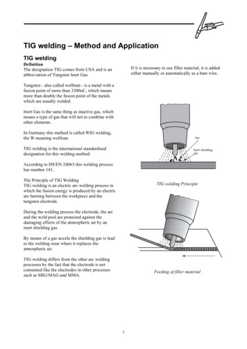
TALAT Lecture 4201Arc Welding Processes:TIG, Plasma Arc, MIG36 pages, 47 figuresBasic Levelprepared by Ulrich Krüger,Schweißtechnische Lehr- und Versuchsanstalt BerlinObjectives: to describe the arc welding processes TIG, Plasma, MIG and their modifications inconnection with aluminium the choice of welding parameters influence on macrostructurePrerequisites: general engineering background basic knowledge in electrical engineeringDate of Issue: 1994 EAA - European Aluminium Association
4201 Arc Welding Processes: TIG, Plasma Arc, MIGTable of Contents4201 Arc Welding Processes: TIG, Plasma Arc, MIG.24201.01 Introduction: Gas-Shielded Arc Welding of Aluminium. 44201.02 TIG Welding. 5Principle of TIG Welding .5TIG Welding Equipment.6Watercooled TIG Welding Torch .7Torch Forms for TIG Welding.8Shielding Gases for Welding and Cutting .8Flow Meters .9Flow Meter for Torches .9Effect of Current and Inert Gas.10Argon Consumption for TIG Welding.11Tungsten Electrodes for TIG Welding.12Influence of Current Type on Weld Pool.13Arc Burning with Alternating Current .14Action of Alternating Current during TIG Welding of Aluminium .14Function of Filter Condenser .15TIG Welding with Pulsating Square-Wave Alternating Current .16TIG Alternating Current Welding Parameters .16Current Loading of Tungsten Electrode.17Manual and Mechanised TIG Welding.18Macrostructure of TIG Welds .184201.03 Plasma Arc Welding . 19Principle of Plasma Arc Welding .19Arc Form during TIG and Tungsten Plasma-Arc Welding.20Weld Pool Form and Heat Affected Zone .20Varying Arc Stabilities.21Principle of the Keyhole Plasma Arc Welding .21Guide Values for the Positive Polarity Plasma Arc Welding .22Principle of the VPPA Welding.23Guide Values for the VPPA Welding .23Macrostructure of VPPA Welds .24Advantages of Plasma Arc Welding over to TIG Welding.24Process Steps of the Plasma Arc Cutting.25Guide Values for Plasma Arc Cutting .26Characteristics which Determine the Quality of a Plasma Arc Cut .26TALAT 42012
4201.04 Metal Inert Gas Welding (MIG). 27Principle of MIG Welding .27Guide Values for the Manual MIG Welding .28MIG Welded Joint Profiles as a Function of Shielding Gas and Welding Parameters.29Influence of Contact Tube Distance on MIG Welding Current and Penetration .29Modifications of MIG Welding .30MIG Welding with Pulsed Current .31Macrostructure of MIG Welds.31Guide Values for Thick-Wire MIG Welding.32Deposit Efficiency of Thick-Wire MIG Welding .33Principle of the Narrow-Gap MIG Welding .33Principle of the Plasma-Arc MIG Welding.34Fields of Application for the Shielded Gas Welding of Aluminium .344201.05 Literature/References . 354201.06 List of Figures. 35TALAT 42013
4201.01 Introduction: Gas-Shielded Arc Welding of AluminiumGas-shielded welding can be divided into the tungsten gas-shielded welding and themetal gas-shielded welding processes. The tungsten gas-shielded welding covers theprocesses tungsten plasma arc welding (PAW)inert-gas tungsten-arc welding (TIG),whereby TIG welding is the most widely used fusion welding process for aluminium.The plasma welding consists only of the plasma-arc welding process which works witha transferred arc.The metal shielded-gas welding is limited to the metal inert-gas welding processoperating with an inert gas as shield, as well as a process combination with plasmawelding (plasma metal shielded-gas welding - PMIG).A further subdivision is possible, depending on the mechanism of metal transfer: without short-circuits by pulsed arc (p)in short-circuit with a short arc (sh)without short-circuits by spray (transfer) arc (sp)partly short-circuit-free and in short-circuit by the mixed arc (m)short-circuiting with a long arc (l), (see Figure 4201.01.01).Gas-Shielded Arc Welding of NGWEGWPMIGGas-Shielded Arc Welding of AluminiumTraining in Aluminium Application TechnologiesTALAT 4201MAGMIG4MAGCspl4201.01.01
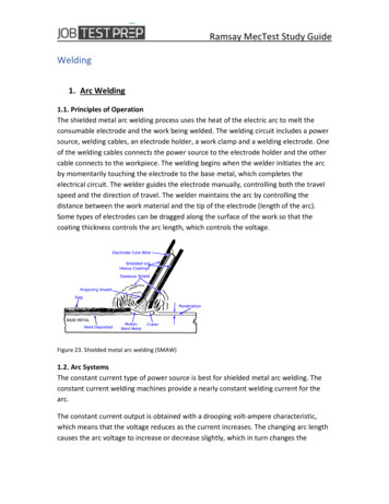
The abbreviations used ed arc weldingGas-shielded tungsten arc weldingGas-shielded metal arc weldingAtomic hydrogen weldingConstricted arc weldingTungsten inert-gas arc weldingMetal inert-gas arc weldingMetal active-gas arc weldingPlasma jet weldingPlasma arc weldingPlasma jet plasma arc weldingGMGMMA(MAGM)MAGCNGWEGWPMIGGas-mixture shielded metal-arc weldingCO2-shielded metal-arc weldingNarrow-gap weldingElectro-gas weldingPlasma MIG weldingpshsplPulsed arcShort arcSpray arcLong arc4201.02 TIG Welding Principle of TIG WeldingTIG welding equipmentWatercooled TIG welding torchTorch forms for TIG weldingShielding gases for welding and cuttingFlow metersFlow meter for torchesEffect of current and inert gasArgon consumption for TIG weldingTungsten electrodes for TIG weldingInfluence of current type on weld poolArc burning with alternating currentAction of alternating current during TIG welding of aluminiumFunction of filter condenserTIG welding with pulsating square-wave alternating currentTIG alternating current welding parametersCurrent loading of tungsten electrodeManual and mechanised TIG weldingMacrostructure of TIG weldsPrinciple of TIG WeldingDuring TIG welding, an arc is maintained between a tungsten electrode and the workpiece in an inert atmosphere (Ar, He, or Ar-He mixture). Depending on the weldpreparation and the work-piece thickness, it is possible to work with or without a filler.The filler can be introduced manually or half mechanically without current or only halfmechanically under current (Figure 4201.02.01).TALAT 42015
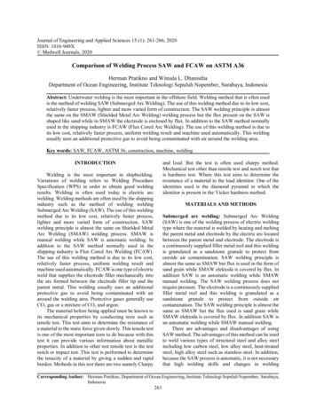
Principle of TIG WeldingTungsten ElectrodeContact (for current)Shielding-GasWelding Power SourceShielding-Gas NozzleFiller MetalHFWeld SeamArcaluWork-PiecePrinciple of TIG Welding4201.02.01Training in Aluminium Application TechnologiesThe process itself can be manual, partly mechanised, fully mechanised or automatic.The welding power source delivers direct or alternating current (partly with modulatedor pulsed current).A major difference between the welding of steel and the TIG welding of aluminium isthe adhering oxide film on the aluminium surface which influences the weldingbehaviour and has to be concerned.This oxide film has to be removed in order to prevent oxides from being entrapped inthe weld. The oxide film can be removed by varying the current type or polarity or alsothrough the use of suitable inert gases.TIG Welding EquipmentTIG Welding EquipmentPressure - Reducing ValveShielding - GasWelding TorchPower Source with Control PanelFoot SwitchaluTraining in Aluminium Application TechnologiesTALAT 4201TIG Welding Equipment64201.02.02
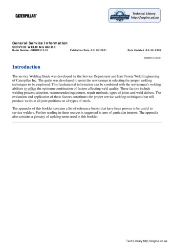
TIG welding equipment consists of the following components: Source of welding current (including welding controls, filtering condensersand pulse modulation) Torch unit with hose packet Gas cylinders with pressure-reducing valve and flow meter(Figure 4201.02.02)Modern welding power sources can deliver both direct and alternating current.The power sources have falling characteristic curves. The current can be varied in stepsor continuously. The voltage required depends on the distance between electrode andwork-piece and determines the operating point on the characteristic line. In modernpower sources designed with transistors, the currents and times can be controlledcontinuously or can be regulated using control programmes.Watercooled TIG Welding TorchDepending on the magnitude of thermal stressing, the torches can be air or watercooled(for 100 A). The watercooling cools both torch and current cable. A flow meterregisters any water shortage, switching off the current in this case and thus preventingtorch overheating.In the region of the gas nozzle and the arc burning location, the cooling action isprovided by the inert gas. The torch should be airtight since humidity has a negativeinfluence on the welding result (hydrogen absorption). The gas nozzle is made of metalor ceramics and insulated from the electricity conducting parts. The tungsten electrodehas a protrusion length of 2 to 4 mm. A torch cap prevents any inadvertent contact withthe electrode (Figure 4201.02.03).Watercooled TIG Welding TorchTorch CapHand GripWater FlowCurrent CableElectrode ColletArgon NozzleTungsten ElectrodeWater InletArgon InletWater OutletWater Flow Monitor(Checks for Water Shortage)aluWatercooled TIG Welding TorchTraining in Aluminium Application TechnologiesTALAT 420174201.02.03
Torch Forms for TIG WeldingTorches of different configurations are necessary to allow for the differentaccessibilities of the weld seams (work-piece form, welding position). Welding atlocations which are difficult to access can be made easier by using the short or elongatedtorch forms.Torch Forms for TIG WeldingNormalElongatedShortaluTorch Forms of TIG Welding4201.02.04Training in Aluminium Application TechnologiesThe torch design and size also depend on the type of cooling (air or water cooled)(Figure 4201.02.04).Shielding Gases for Welding and CuttingThe type of shielding gas used has a major influence on the weld quality. Only inertgases and their mixtures are utilised for welding aluminium, as opposed to the weldingof steels (Figure 4201.02.05). The required purity of the gases must be guaranteed. It ismost important that the limiting value for humidity is not exceeded. The gases are eitherdelivered in compressed form in cylinders or obtained by a vaporisation process(liquefied gas) through pipe lines.TALAT 42018
Shielding Gases for Welding and CuttingDesignationGroup Nr.RIM1M2M3CFoxidisingCO ²O²Components in vol. %inertreducing inactivH²N²ArHe1rest (1-2)1 . 1521231234bal. (1-2)15 . 3512312312100 0 . 5 0 . 5 0 . . 3 0 . 5 0 . 3 5 . 25 3 . 10 5 . 25 0 . 8 25 . 50 10 . 15 5 . 50 8 . 15100rest 0 . 30rest (1)rest (1-2)rest (1-2)rest (1-2)rest (1-2)rest (1-2)rest (1-2)rest (1-2)rest (1-2)rest (1-2)rest (1-2)10020 . 80aluTraining in Aluminium Application TechnologiesRemarksTIG, PAW, rootprotection, plasmaarc cuttingreducingTIG, MIG, PAWroot protectioninert 0 . 5weakoxidisingMAGstronglyoxidising0 . 301ProcessrestShielding Gases for Welding and Cuttingroot protectionreducing4201.02.05Flow MetersThe pressure of the gas contained in cylinders is reduced by pressure-reducing valves(Manometers for indicating cylinder pressure).The amount of gas flowing in l/min is controlled via a regulating valve and indicated bythe flow meter. In order to prevent any errors, the pressure-reducing valves have acolour code corresponding to the gas type (black for inert gases).The type of gas used is also indicated in the manometer (Figure 4201.02.06).Flow Meter for TorchesFlow meters which can be fixed directly to the torch nozzle have proved to be verypractical. This shows the amount of gas actually passing through the torch in l/min. Acorrection factor has to be used for the varying gas densities of the Ar-He mixtures orthe pure helium used (He: 0.1785 kg/Nm3 , Ar: 1.7844 kg/Nm3) (Figure 4201.02.07).TALAT 42019
Gas Flow MetersManometer (for Gas Cylinder Pressure)Indication ofGas TypeFlow Meter(With Floating Ball)Flow Control ValveColor Codefor Gas TypealuFlow Meters4201.02.06Training in Aluminium Application TechnologiesGas Flow Meters for TorchesAr 100 %Ar75 % He 25% : f 1.00Ar50 % He 50 % : f 0.75Ar25 % He 75 % : f 0.57He 100 %alu: f 1.00Flow Meters for Torches: f 0.324201.02.07Training in Aluminium Application TechnologiesEffect of Current and Inert GasBoth direct and alternating currents are used for welding aluminium. The weld pool andthe weld forms can be regulated by controlling the current type and the polarity. Theheat developed is highest when helium is used.In direct-current, straight-polarity welding (electrode is negative with respect toaluminium), the heating of the electrode is kept to a minimum but the cleaning action onthe weld pool is also minimum. Helium is used as the shielding inert gas. Thebreakdown of the oxide film is a result of the thermal stressing, i.e., melting occurs.Because of its high melting point (ca. 2050 C), the oxide layer cannot be melted usingargon as the shielding gas.TALAT 420110
Effect of Current and Inert Gas Heat Efficiency70 %30 %50 %Cleaning EfficiencyBadGoodGoodInert GasHeAr - HeAr -HeHelium produces a deep weld poolaluArgon produces a flat weld pool4201.02.08Effect of Current and Inert GasTraining in Aluminium Application TechnologiesWhen direct-current reverse-polarity is used (electrode is positive with respect toaluminium), excessive heating of the electrode occurs, so that the electrode life isreduced or, as in some cases, even melting of the electrode end can occur.The reverse polarity (electrode positive) has a lower energy density so that the weld poolis shallower than in the case of straight polarity (electrode negative). Thus it is only usedfor welding thin-walled parts with low currents. However, good cooling and largediameter electrodes are necessary. The alternating-current welding is a compromisesolution (Figure 4201.02.08).Argon Consumption for TIG WeldingArgon Consumption for TIG WeldingArgon Consumptionl \ min10soyiumAllndatseTiBael kcNi987Alumin6ium5450,41,02,03,0 mm4,010 mm 20Gas Nozzle DiameterWork - Piece ThicknessaluTraining in Aluminium Application TechnologiesArgon Consumption for TIG Welding4201.02.09The amount of shielding gas required depends on the material used and its thickness.TALAT 420111
The gas consumption for titanium is higher than for steel, since a gas absorption by theformer material must be prevented even at lower temperatures.Thus, trailing nozzles have to be used.The gas nozzle diameter has to be optimised for the electrode diameter used.Because of its lower density, the amount of argon required is larger than the heliumamount needed (4201.02.09).Tungsten Electrodes for TIG WeldingOxide additions (oxides of thorium, zircon, lanthan and cer) to the tungsten electrodereduce the electron emission energy (pure tungsten 5.36 eV, thorated 2.62 eV).This improves: the arc stability electrode life current loading capacity arc igniting properties.Tungsten Electrodes for TIG WeldingDesignationMaterialNo.OxideAdditionsWt. %Impuri tiesWt. % 0.20W2.6005-WT 102.60220.90 - 1.20 ThOWT 202.60261.80 - 2.20 ThOWT 302.60302.80 - 3.20 ThOWT 402.60363.80 - 4.20 ThOWZ 42.60500.30 - 0.50 ZrOWZ 82.60620.70 - 0.90 ZrOWZ 102.60100.90 - 1.20 0.20 RestYellow1018 0.20RestRed20020.20 RestViolet40030.20 RestOrange20030.20 RestBrown80010.20 RestWhite90100.20 RestBlack9005Wt. %Tungsten Electrodes for TIG Welding4201.02.10Training in Aluminium Application TechnologiesThorated tungsten electrodes are most commonly used. For nuclear reactor construction,zircon oxide additions have proved effective. Lanthated electrodes are used for microplasma welding and for plasma arc cutting (Figure 4201.02.10).TALAT 420112
Influence of Current Type on Weld PoolThe type of current used influences the weld pool created and the weld form as well asthe form of the electrode used.Current loading and life of the electrode are much higher when the electrode is set to anegative polarity, since the emission of electrons from this hot electrode tip requires lessenergy than in the case of positive electrode polarity, where the electrons have to beemitted from the cold work-piece surface.The electrons emitted from the negative electrode bombard the work-piece giving uptheir kinectical energy as heat to produce a narrow and deep weld pool. The electrode tipis thin and narrowly tapered. The high-melting oxide film is not destroyed here, i.e.,there is no cleaning action of the weld pool.Influence of Current Type on Weld Pool( )(-)Alternating CurrentDirect CurrentaluInfluence of Current Type on Weld PoolTraining in Aluminium Application Technologies4201.02.11Conditions are reversed when the electrode is made positive with respect to the workpiece. The electrons give up their kinetic energy to the electrode, causing an excessiveheating of the electrode. Consequently, large-diameter electrodes with wide-angled tipshave to be used. The weld pool is broader and flatter.Alternating current welding combines the characteristics of the above mentioned twovariations (Figure 4201.02.11).TALAT 420113
Arc Burning with Alternating CurrentIn the alternating current welding, both current and voltage pass through a zero-phase,causing a periodic extinction of the arc. High voltage pulses are essential both in thenegative as well as in the positive half-cycle to ignite the arc after each zero-phase iscrossed (Figure 4201.02.12).High Voltage ImpulseVoltage ---TimeHigh Voltage ImpulsealuTraining in Aluminium Application TechnologiesArc Burning with Alternating Current4201.02.12Action of Alternating Current during TIG Welding of AluminiumThe oxide film can be destroyed or broken up thermally under helium gas shielding(direct-current, straight-polarity - electrode negative) or mechanically (alternatingcurrent under argon or Ar-He mixture).Action of Alternating Currentduring TIG Welding of AluminiumGas Ions Bombarding the SurfaceBreak Up the Oxide SkinDiscarded Theory:Electrons Emitting from the MaterialBreak Up the Oxide FilmArOxide SkineAluminiumaluTraining in Aluminium Application TechnologiesAction of Alternating Current during TIG Weldingof Aluminium4201.02.13During the positive phase of the alternating current welding, gas ions are acceleratedaway from the electrode (anode) in the direction of the work-piece.TALAT 420114
The bombardment with the relatively heavy ions breaks up the oxide film, therebycleaning the weld pool (cleaning half-wave). At the same time, an electron streambombards the electrode. The kinetic energy of the electrons is converted here, causingexcessive heating of the electrode (Figure 4201.02.13).A cooling half-wave in which the electrode has a negative polarity follows the cleaninghalf-cycle (electrode positive). The electrons emitting from the electrode (cathode)bombard the work-piece causing the temperature to rise, without, however, being able tobreak up the oxide film. On the other hand, the ions striking the electrode hardly causeany heating of the electrode, so that the previously heated electrode can cool down. Thealternating polarity increases the life of the electrode and also has the desired cleaningeffect on the weld.According to current theories, a bombardment with electrons has no cleaning effect. Therelease energy of electrons from the oxide layer is 50 % less than from pure aluminium.Consequently, the electrons are emitted from the oxide film and not from the metalsurface lying under it. Thus, a "tunnelling" or breaking up of the oxide film is notpossible.Function of Filter CondenserWhile welding with alternating current, the maximum voltage amplitudes during thepositive and negative half-cycle are not the same; one refers to this as the rectifyingeffect. The differences in the electron emission characteristics of the metal (or oxide)and the electrode cause the alternating current to be unbalanced.Function of Filter CondenserPositive and negative half-cycles unbalanced due to rectifier effectVoltage 0-Time-Positive and negative half-cycles balanced through the use of filtering condensersVoltage 0--Time-aluFunction of Filter Condenser4201.02.14Training in Aluminium Application TechnologiesThe electron emission of the incandescent tip of the tungsten electrode is very muchlarger than that of the relatively cold weld pool surface, so that the amplitude of thenegative half-cycle is higher. This effect reduces the cleaning action and the stability ofthe arc.TALAT 420115
Filter condensers are used to produce a balanced wave (Figure 4201.02.14).TIG Welding with Pulsating Square-Wave Alternating CurrentWith modern power sources it is possible to weld with impulse overlay and alternatingpolarity of the direct current as well as with square-waved alternating current. Thus it ispossible to choose the pulse duration and pulse pauses as well as the pulse amplitudeindependently.TIG Welding with Pulsating Square-WaveAlternating CurrentPositive Half-WaveNegative Half-Wave VoltagePositive polarity of electrode:- breaks up the oxide skin,- excessive heating of electrode tipTime1Cycle-aluTraining in Aluminium Application TechnologiesNegative electrode polarity:- lower temperatures,- cooling of electrode tip,- base material meltsTIG Welding with Pulsating Square-WaveAlternating Current4201.02.15The balanced-wave alternating current (positive and negative half-cycles aresymmetrical) can be altered so that the cleaning half-cycle duration is reduced and thecooling-phase half-cycle duration increased. Thus, the positive phase - heavily reducedin duration and amplitude - serves only as the cleaning phase, and the negative phaseexclusively as the melting phase. The square-wave form of the alternating current hasthe added advantage that the steep transition from positive to negative guarantees theignition of the arc without having to use a high frequency overlaying voltage (Figure4201.02.15).TIG Alternating Current Welding ParametersThe maximum current strengths used for alternating current welding are around 400 A,the current strength for direct current welding being around 600 A (negative polarityunder helium). The guiding values for manual and fully mechanised welding can beobtained from the corresponding tables (see Figure 4201.02.16).The direct current welding with helium is generally fully mechanised. The small arclength (ca.1mm) which must be maintained for this type of welding makes manualwelding very difficult.TALAT 420116
TIG Alternating Current Welding ParametersWorkThicknessmm1246810Alternating WeldingCurrent in AWelding PositionPAPFPE50- 6080-100160-190250-290300-350330-380alu40- 6075- 95155-185210-250240-290250-300Tungsten Welding WeldingArgonNo. ofElectrode RateRod Consumption PassesDiameterDiametermmcm/minmml/min40- 6070- 4.84.8-6.43030282520152.02.03.04.04.06.03- 54- 74- 96-108-1210-1411122-33-44201.02.16TIG Alternating Current Welding ParametersTraining in Aluminium Application TechnologiesCurrent Loading of Tungsten ElectrodeThe current strengths required can be estimated from the form of the tungsten electrode.For direct current welding, the electrode is ground to an angle of ca. 20 to 25 . The arcshould surround the tip symmetrically. Too high currents cause the tip to melt. Due tothe lower thermal stressing, small-diameter electrodes can be used for direct currentwelding.Current Loading of Tungsten ElectrodeAlterning CurrentOverloadedaluProperLoadingDirect CurrentUnderloadedProperLoadingCurrent Loading of the Tungsten ElectrodeTraining in Aluminium Application TechnologiesOverloaded4201.02.17During alternating current welding, thicker electrodes are used. When the proper currentstrength is used, a hemispherical molten bead is formed at the end of the electrode. Thisbead, however, should not be allowed to grow too large in size. When the currentstrength is too low, only a local melting occurs (Figure 4201.02.17).TALAT 420117
Manual and Mechanised TIG WeldingDepending on the torch manipulation and the filler metal introduction, one refers to manual welding (torch and filler metal are manipulated by hand, as in gas welding) orfully mechanised welding (torch and filler metal are manipulated mechanically)(Figure 4201.02.18).Manual and Mechanised TIG WeldingManual TIG WeldingaluFully Mechanised TIG WeldingManual and Mechanised TIG Welding4201.02.18Training in Aluminium Application TechnologiesMacrostructure of TIG WeldsCurrent type and polarity as well as the shielding gas type influence the weld geometry.The micrograph shows a flat and broad penetration during positive polarity under argongas shielding. The mixing of helium to argon in the alternating current welding,produces a broader penetration profile (Figure 4201.02.19).Macrostructure of TIG WeldingsAlZn4,5Mg1 F35; 2.5 mm thick, Filler Metal S-AlMg4,5 Mn; Square Butt Joint; Position PAAlternating Current;100 ArAlternating Current;50 Ar 50 HeDirect Current;100 Ar;Electrode vealuMacrostructure of TIG WeldingsTraining in Aluminium Application TechnologiesTALAT 4201184201.02.19
4201.03 Plasma Arc Welding Principle of plasma arc weldingArc form during TIG and tungsten plasma-arc weldingWeld Pool Form and Heat Affected ZoneVarying Arc StabilitiesPrinciple of the Keyhole Plasma Arc WeldingGuide Values for the Positive Polarity Plasma Arc WeldingPrinciple of the VPPA WeldingGuide Values for the VPPA WeldingMacrostructure of VPPA WeldsAdvantages of Plasma Arc Welding over to TIG WeldingProcess Steps of the Plasma Arc CuttingGuide Values for Plasma Arc CuttingCharacteristics which Determine the Quality of a Plasma Arc CutPrinciple of Plasma Arc WeldingThermal plasma consists of electrons, ions and neutral particles under high temperatureand subject to a disordered violent movement. The molecules are partly dissociated andthe atoms ionised. During collision with the work-piece surface, these give their energyup to the work and recombine. (Figure 4201.03.01)Gas-Shielded Arc Welding of MApshmNGWEGWPMIGGas-Shielded Arc Welding of AluminiumMAGCspl4201.03.01Training in Aluminium Application TechnologiesThe plasma is concentrated in the inside of the jet, thereby delivering a narrow plasmajet with a very high energy density. The plasma arc is, therefore, constricted and arcsbetween the tungsten electrode and the work-piece (Figure 4201.03.02). The shieldinggases used here are exclusively inert gases like argon, helium or a mixture of thesegases. The tungsten electrode has a negative polarity and the work-piece a positivepolarity (straight polarity).TALAT 420119
Principle of Plasma Arc WeldingTungsten ElectrodeContact (for current)Shielding-GasIgniting EquipmentShielding-Gas NozzlePlasma-GasPlasma-Gas NozzleFiller MetalWeldingPower SourceWeld SeamTransferred ArcaluWork-PiecePrinciple of Plasma Arc Welding4201.03.02Training in Aluminium Application TechnologiesArc Form during TIG and Tungsten Plasma-Arc WeldingCompared to the TIG arc, the constricted plasma arc has a much lower divergence, i.e.,much larger changes in arc length can be tolerated. Thus, for example, a 20 % increaseof arc cross-section corresponds to a ten times larger length of the plasma arc than of theTIG arc. This explains the relative insensitivity of the plasma arc to surface unevenness(Figure 4201.03.03).TIGPAW45 6 20 % Change in Cross-Section of ArcaluArc Form during TIG and Tungsten Plasma-Arc Welding 4201.03.03Training in Aluminium Applicatio
During TIG welding, an arc is maintained between a tungsten electrode and the work- piece in an inert atm