Transcription
Introduction to Radar SystemsDr. Robert M. O’DonnellMIT Lincoln LaboratoryIntroduction-1AG 6/18/02
Disclaimer of Endorsement and Liability The video courseware and accompanying viewgraphs presented on thisserver were prepared as an account of work sponsored by an agency of theUnited States Government. Neither the United States Government nor anyagency thereof, nor any of their employees, nor the Massachusetts Instituteof Technology and its Lincoln Laboratory, nor any of their contractors,subcontractors, or their employees, makes any warranty, express orimplied, or assumes any legal liability or responsibility for the accuracy,completeness, or usefulness of any information, apparatus, products, orprocess disclosed, or represents that its use would not infringe privatelyowned rights. Reference herein to any specific commercial product,process, or service by trade name, trademark, manufacturer, or otherwisedoes not necessarily constitute or imply its endorsement, recommendation,or favoring by the United States Government, any agency thereof, or any oftheir contractors or subcontractors or the Massachusetts Institute ofTechnology and its Lincoln Laboratory. The views and opinions expressed herein do not necessarily state or reflectthose of the United States Government or any agency thereof or any of theircontractors or subcontractorsIntroduction-2AG 6/18/02MIT Lincoln Laboratory
Introduction to Radar SystemsIntroductionMIT Lincoln LaboratoryIntroduction-3AG 6/18/02
Acknowledgement Developers of Tutorial Material– Dr. Eric D. Evans– Dr. Andrew D. Gerber– Dr. Robert M. uction-4AG 6/18/02Dr. Robert G. AtkinsDr. Pamela R. EvansDr. Robert J. GalejsDr. Jeffrey S. HerdDr. Claude F. NoiseuxDr. Philip K. W. PhuDr. Nicholas B. PulsoneDr. Katherine A. RinkDr. James WardDr. Stephen D. WeinerAnd many othersMIT Lincoln Laboratory
Background on the Course One of Many Radar Courses Presented at the Laboratory Relatively Short–– Introductory in Scope–– Introduction-5AG 6/18/02Basic Radar ConceptsMinimal Mathematical FormalismPrerequisite – A College Degree– 10 lectures40 to 60 minutes eachPreferred in Engineering or Science, but not RequiredMore Advanced Issues Dealt with in Other Laboratory RadarCoursesMIT Lincoln Laboratory
OutlineIntroduction-6AG 6/18/02 Why radar? The basics Course agendaMIT Lincoln Laboratory
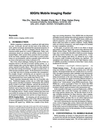
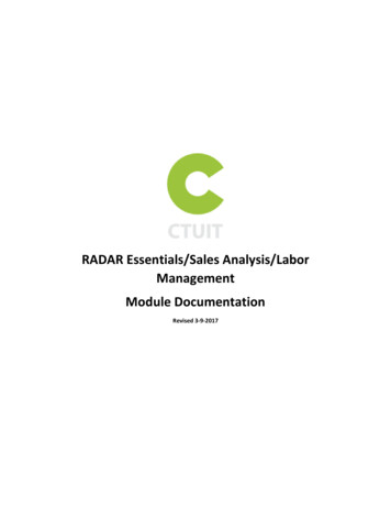
What Means are Available forLifting the Fog of War ?D-Day 1The Invasion of NormandyD-DayCourtesy of National Archives.Introduction-7AG 6/18/02MIT Lincoln Laboratory
What Means are Available forLifting the Fog of War ?Courtesy of US Marine Corp, History Division.Iwo Jima1945Courtesy of National Archives.Introduction-8AG 6/18/02Courtesy of National Archives.MIT Lincoln Laboratory
Military Means of SensingRadar Ground surveillance/reconnaissance/ID Laser targeting Night vision Space surveillance Missile n-9AG 6/18/02AcousticOther Chem/Bio Surveillance Sonar Radiological Tracking Blast detection Fire control Troop movement Target ID/detectiondiscrimination Ground surveillance/reconnaissance Ground mapping Moving target detection Air traffic control Missile seekers Long range All-weather Day/night 3-space target location Reasonably robust againstcountermeasuresMIT Lincoln Laboratory
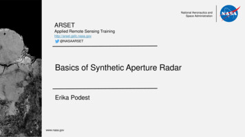
Early Days of RadarChain Home Radar, Deployment Began 1936Chain Home Radar Coveragecirca 1940(21 Early Warning Radar Sites)Sept 2006 Photograph ofThree Chain HomeTransmit Towers, nearDoverDoverRadar SiteCourtesy of Robert Cromwell.Used with permission.Introduction-10AG 6/18/02MIT Lincoln Laboratory
Chain Home Radar SystemTypical Chain Home Radar SiteRadar Parameters Frequency– Wavelength– –350 kWDetection Range–Introduction-11AG 6/18/02About 100oPeak Power– Dipole Array onTransmitCrossed Dipoles onReceiveAzimuth Beamwidth– 10-15 mAntenna– 20-30 MHz 160 nmi onGerman BomberMIT Lincoln Laboratory
Chain Home Transmit & Receive AntennasTwo Transmitter Towersλ/2360'One Receiver Towerλ/2240'215'95'45'0'Main Gap FillerAntenna AntennaTransmit AntennaIntroduction-12AG 6/18/02Receive AntennaMIT Lincoln Laboratory
Radar and “The Battle of Britain”Chain Home Radar Coveragecirca 1940(21 Early Warning Radar Sites) The Chain Home Radar– British “Force Multiplier”during the Battle of Britain” Timely warning of directionand size of German aircraftattacks allowed British to– Focus their limited numbersof interceptor aircraft– Achieve numerical paritywith the attacking Germanaircraft Effect on the War– Germany was unable toachieve Air Superiority– Invasion of Great Britainwas postponed indefinitelyIntroduction-13AG 6/18/02MIT Lincoln Laboratory
Surveillance and Fire Control RadarsCourtesy of Raytheon.Used with permission.Courtesy of Raytheon.Used with permission.Courtesy of Raytheon. Used with permission.Courtesy of Raytheon. Used with permission.Courtesy of US Navy.MIT Lincoln LaboratoryIntroduction-14Courtesy ofGlobal Security.AG 6/18/02Used with permission.Photo courtesyof ITTCorporation.Used withpermission.Courtesy of Raytheon. Used with permission.
Airborne and Air Traffic Control RadarsCourtesy of US Air Force.Courtesy of US Navy.Courtesy of Northrop Grumman.Used with permission.Courtesy Lincoln Laboratory.Courtesy of US Air Force.Introduction-15AG 6/18/02MIT Lincoln LaboratoryCourtesy of US Air Force.Courtesy of US Air Force.Courtesy of Boeing Used with permission
Instrumentation RadarsIntroduction-16AG 6/18/02MIT Lincoln Laboratory
OutlineIntroduction-17AG 6/18/02 Why radar? The basics Course agendaMIT Lincoln Laboratory
RADARRAdio Detection And ttedPulseReflectedPulse(“echo”)Radar observables: Target range Target angles (azimuth & elevation) Target size (radar cross section) Target speed (Doppler) Target features (imaging)Introduction-18AG 6/18/02MIT Lincoln Laboratory
Electromagnetic WavesCourtesy Berkeley National LaboratoryRadar FrequenciesIntroduction-19AG 6/18/02MIT Lincoln Laboratory
Properties of WavesRelationship Between Frequency and Wavelengthλ1, 2, 3, Speed of light, cc 3x10⁸ m/sec 300,000,000 m/secFigure byMIT OCW.Frequency (1/s) Examples:Introduction-20AG 6/18/02Frequency100 MHz1 GHz3 GHz10 GHzSpeed of light (m/s)Wavelength λ (m)Wavelength3m30 cm10 cm3 cmMIT Lincoln Laboratory
Properties of WavesPhase and AmplitudeAmplitude (volts)APhase, θAmplitude (volts)A sin(θ )90 phase offsetAPhase, θIntroduction-21AG 6/18/02A sin(θ 90 o )MIT Lincoln Laboratory
Properties of WavesConstructive vs. Destructive AdditionΣΣPartially Constructive(somewhat out of phase)Constructive(in phase)ΣDestructive(180 out of phase)Introduction-22AG 6/18/02ΣNon-coherent signals(noise)MIT Lincoln Laboratory
PolarizationyElectric FieldElectric FieldElectromagnetic WaveElectromagnetic WaveMagneticMagnetic FieldFieldxHorizontal PolarizationVertical PolarizationyyExIntroduction-23AG 6/18/02zxEzMIT Lincoln Laboratory
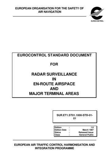
Radar Frequency BandsWavelength1 kmFrequencyUHF1m1 MHzL-Band1 GHzS-Band1 μm1 mm109 Hz1 nm1012 HzIRUVVisibleC-BandKuKKaWX-BandVHF0130 20Introduction-24AG 6/18/022310 945678Allocated Frequency (GHz)8 765Wavelength (cm)491011123MIT Lincoln Laboratory
IEEE Standard Radar Bands(Typical Use)HFVHFUHFIntroduction-25AG 6/18/023 – 30 MHz30 MHz–300 MHz300 MHz–1 GHzL-Band1 GHz–2 GHzS-Band2 GHz–4 GHzC-Band4 GHz–8 GHzX-Band8 GHz–12 GHzKu-Band12 GHz–18 GHzK-Band18 GHz–27 GHzKa-Band27 GHz–40 GHzW-Band40 GHz – 100 GHzSearchRadarsSearch &Track RadarsFire Control &Imaging RadarsMissileSeekersMIT Lincoln Laboratory
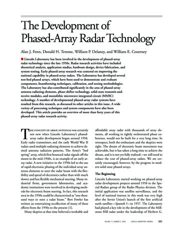
Radar Block terWaveformGeneratorSignal ProcessorAntennaReceiverPulseCompressionA/DMain ComputerDetectionIntroduction-26AG 6/18/02Tracking &ParameterEstimationDopplerProcessingConsole /DisplayRecordingMIT Lincoln Laboratory
Radar Range EquationAntenna Aperture ATransmitted PulseTransmit Power PTTarget Cross Section σReceived PulseRFigure by MIT OCW.Received Signal EnergyIntroduction-27AG TargetRCSPT4πAλ214πR21LσSpread ReceiveFactor Aperture14πR2ADwellTimeτMIT Lincoln Laboratory
Signal-to-Noise RatioReceived SignalNoiseSNR Introduction-28AG 6/18/02Received Signal EnergyNoise EnergyMIT Lincoln Laboratory
What the #@!*% is a dB?The relative value of two things, measured on alogarithmic scale, is often expressed in deciBel’s (dB)Example:Signal-to-noise ratio (dB) 10 log 10Factor of:101001000.1,000,000Introduction-29AG 6/18/02ScientificNotation101102103106Signal PowerNoise PowerdB1020300 dB factor of 1-10 dB factor of 1/10-20 dB factor of 1/100603 dB factor of 2-3 dB factor of 1/2MIT Lincoln Laboratory
Pulsed RadarTerminology and ConceptsPeak powerPowerPulse lengthTargetReturnPulse repetition interval(PRI)Duty cycle TimePulse lengthPulse repetition intervalAverage power Peak power * Duty cyclePulse repetition frequency (PRF) 1/(PRI)Continuous wave (CW) radar: Duty cycle 100% (always on)Introduction-30AG 6/18/02MIT Lincoln Laboratory
Pulsed RadarTerminology and ConceptsPeak powerPowerPulse length100 μsec1 MWTargetReturn1 μWPulse repetition interval(PRI) 1 msecDuty cycle Pulse lengthPulse repetition intervalTime10%Average power Peak power * Duty cycle100 kWPulse repetition frequency (PRF) 1/(PRI)1 kHzContinuous wave (CW) radar: Duty cycle 100% (always on)Introduction-31AG 6/18/02MIT Lincoln Laboratory
Brief Mathematical DigressionScientific Notation and Greek 0MegaMHz, 60.000,001microμsecMHz MegahertzMW MegawattIntroduction-32AG 6/18/02MIT Lincoln Laboratory
Radar WaveformsWhat do radars transmit?Waves?or Pulses?Introduction-33AG 6/18/02Waves, modulatedby “on-off” action ofpulse envelopeMIT Lincoln Laboratory
Radar Waveforms (cont’d.)FrequencyPulse at single frequencyTimeFrequencyPulse with changing Introduction-34AG 6/18/02MIT Lincoln Laboratory
Radar Range MeasurementengaRTargetdtteinsm searT PultedceflRe ulseP Target range cτ2where c speed of lightτ round trip timeCourtesy of Raytheon. Used with permission.Introduction-35AG 6/18/02MIT Lincoln Laboratory
Antenna GainIsotropic antennaDirectional antennaG antenna gainR.Introduction-36AG 6/18/02MIT Lincoln Laboratory
Propagation Effects on Radar Performance Atmospheric attenuation Reflection off of earth’s surface Over-the-horizon diffraction Atmospheric etheenvironmentenvironmentIntroduction-37AG 6/18/02MIT Lincoln Laboratory
Radar Cross Section (RCS)RCSIncidentPower Density(Watts/m2)xσ(m2) ReflectedPower(Watts)Radar Cross Section (RCS, or s) is the effective crosssectional area of the target as seen by the radarmeasured in m2, or dBm2Introduction-38AG 6/18/02MIT Lincoln Laboratory
Signal ProcessingPulse CompressionProblem: Pulse can be very long; does not allow accurate range measurement1 msec x c 150 km2?Figure byMIT OCW.Solution: Use pulse with changing frequency and signal process using “matched filter”MatchedFilterUncompressed pulseIntroduction-39AG 6/18/02Compressed pulseMIT Lincoln Laboratory
essedPulseΔR debandWaveformTimeIntroduction-40AG 6/18/02HighRangeResolutionCompressedPulseRangeMIT Lincoln Laboratory
.Why Bandwidth is ImportantWideband Target ProfileBandwidthPowerVery High(X 30)High(X 10)Medium(X 3)LowRelative Range (m)Introduction-41AG 6/18/02MIT Lincoln Laboratory
Detection of Signals in NoiseDetected dRMSNoiseLevelRangeIntroduction-42AG 6/18/02MIT Lincoln Laboratory
Coherent IntegrationVoltageSignal buriedin Noise(SNR 0 dB)Pulse 1 Pulse 20 Pulse 3Signal integratedout of Noise(SNR increases by N). Signals are same each time;add “coherently” (N2) Noise is different each time;doesn’t add coherently (N)Introduction-43AG 6/18/02 x 2Power Pulse N0MIT Lincoln Laboratory
Doppler EffectObserver AObserver BObserver A HearsObserver B HearsDriver HearsFigure by MIT OCW.Introduction-44AG 6/18/02MIT Lincoln Laboratory
Doppler Shift Conceptλλf ccλfvcf’ f (2v/λ)λ’Introduction-45AG 6/18/02DopplershiftMIT Lincoln Laboratory
Why Doppler is ImportantSurface RadarClutter returns are much larger thantarget returns however, targets move, clutterdoesn’t.Airborne RadarNote: if you’re moving too, you needto take that into account.DopplerDoppler letslets youyou separateseparate thingsthings thatthat areare movingmoving fromfrom thingsthings thatthat aren’taren’tIntroduction-46AG 6/18/02MIT Lincoln Laboratory
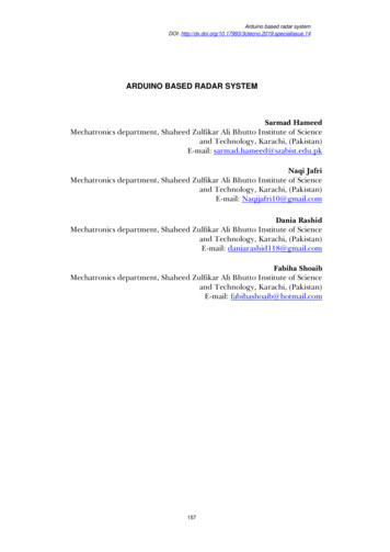
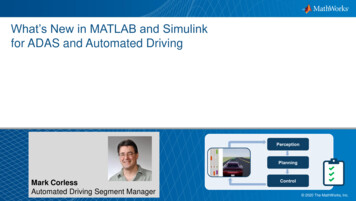
Clutter Doppler Spectra70LandSeaRainChaffBirdsRelative Power (dB)605040302010Target0-10-20050100150200Velocity (m/s)Introduction-47AG 6/18/02MIT Lincoln Laboratory
Radar Block terWaveformGeneratorSignal ProcessorAntennaReceiverPulseCompressionA/DMain ComputerDetectionIntroduction-48AG 6/18/02Tracking &ParameterEstimationDopplerProcessingConsole /DisplayRecordingMIT Lincoln Laboratory
OutlineIntroduction-49AG 6/18/02 Why radar? The basics Course agendaMIT Lincoln Laboratory
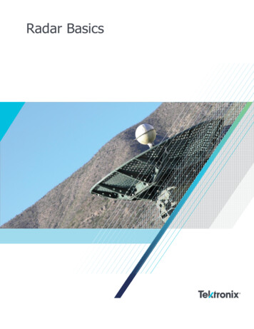
Introduction to Radar Systems TutorialAgenda Introduction Radar Equation Propagation Effects Target Radar Cross Section Detection of Signals in Noise & Pulse Compression Radar Antennas Radar Clutter and Chaff Signal Processing-MTI and Pulse Doppler Tracking and Parameter Estimation Transmitters and ReceiversIntroduction-50AG 6/18/02MIT Lincoln Laboratory
References Introduction-51AG 6/18/02Skolnik, M., Introduction to Radar Systems, New York,McGraw-Hill, 3rd Edition, 2001Nathanson, F. E., Radar Design Principles, New York,McGraw-Hill, 2nd Edition, 1991Toomay, J. C., Radar Principles for the Non-Specialist, NewYork, Van Nostrand Reinhold, 1989Buderi R., The Invention That Changed the World, NewYork, Simon and Schuster, 1996MIT Lincoln Laboratory
One of Many Radar Courses Presented at the Laboratory Relatively Short - 10 lectures - 40 to 60 minutes each Introductory in Scope - Basic Radar Concepts - Minimal Mathematical Formalism Prerequisite - A College Degree - Preferred in Engineering or Science, but not Required More Advanced Issues Dealt with in Other Laboratory Radar