Transcription
Bridge Software Institute - NewsletterFALLIssue #23Page 12018Index TableWhat’s New at BSIPage 2FB-MultiPier v5.4ProgramEnhancementsPage 2Modeling TipsIn this issue we discuss features that wereimplemented in FB-MultiPier v5.4.Page 7Technical SupportPage 8Program StatusPage 9FB-MultiPier v5.4FB-Deep v2.05Atlas v7.0Contact BSIPage 10Bridge Software InstituteUniversity of FloridaPO Box 116580Gainesville, FL 32611Online: bsi.ce.ufl.eduEmail: bsi@ce.ufl.eduFax: (352) 392-3697The Bridge Software Institute (BSI) encourages correspondence from allengineers making use of the program, particularly when suggestions for newfeatures come to light. These suggestions may be general in nature or veryspecific to the needs of a given project. We firmly believe that you are in the bestposition to know what those needs are!In this release of FB-MultiPier (v5.4), the enhancements listed below were all aresult of YOUR suggestions:a) Liqueified sand p-y model.b) Simplified hybrid liquefied sand p-y model.c) Soil with both cohesion and internal friction p-y model.d) Loess p-y model.e) Piedmont residual soil p-y model.f) Massive rock p-y model.g) Linear (constant subgrade modulus) p-y model.h) Exclusion of skin friction for embedded casing lengths of drilled shafts.Please contact BSI at bsi@ce.ufl.edu with your ideas.
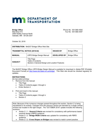
Bridge Software Institute - NewsletterIssue #23Page 2FALL2018Index TableWhat’s New at BSIPage 2FB-MultiPier v5.4ProgramEnhancementsPage 2What’s New at BSIWe are pleased to announce the release of FB-MultiPier v5.4. This program and otherbridge design software are available for download from the BSI website. The newversion of FB-MultiPier (v5.4) contains fixes to the latest reported errors and alsoincludes a number of new features.Program EnchancementsModeling TipsPage 7Technical SupportPage 8Program StatusPage 9FB-MultiPier v5.4FB-Deep v2.05Atlas v7.0Lateral Resistance (p-y) modelsTo provide engineers with more options in characterizing lateral resistance of deepfoundations in a variety of soils and rocks, seven new p-y curves have been implementedin FB-MultiPier. Shown in Fig. 1 are comparisons of the p-y relationships, relative tomanually generated p-y curves, based on the references indicated below. Excellentagreement is achieved for all cases. For manual curve generation, all studied piles andshafts were 2 ft in diameter and the results are presented at a depth of 3 ft beneath theground surface elevation. Additional examples can be found here. Listed below are briefdescriptions of the newly implemented p-y models.Contact BSIPage 10Bridge Software InstituteUniversity of FloridaPO Box 116580Gainesville, FL 32611Online: bsi.ce.ufl.eduEmail: bsi@ce.ufl.eduFax: (352) 392-3697a)Liquefied SandThe p-y relationship for liquefied sand was developed by Rollins et al. (2005a) and Rollinset al. (2005b). The initial curve portions are concave-up (the slope of the curve increasesas deflection increases). This p-y curve is presented in Fig. 1a and models the lateralresistance of a pile in a liquefied sand at 3 ft depth.b)Simplified Hybrid Model for Liquefied SandThe simplified hybrid model for liquefied sand (p-y relationship) was developed byFranke and Rollins (2013). This p-y relationship is applicable to a wide range of soil types,relative densities, pile/shaft diameters, and loading conditions. An example p-y curve ispresented in Fig. 1b and models the lateral resistance of a pile in a liquefied sand with0.9 psi residual strength.
Bridge Software Institute - NewsletterIssue #23Page 3FALL2018Index TableWhat’s New at BSIPage 2FB-MultiPier v5.4ProgramEnhancementsPage 2c)Soil with Both Cohesion and Internal FrictionThe “c-φ” p-y relationship was implemented by drawing upon on the work of Ismael(1990) on cemented soils having both components of shear strength, c and φ. Theimplemented p-y curve is plotted in Fig. 1c and models the lateral resistance of a pile ina c - φ soil with 21 psi undrained shear strength and 30 internal friction angle.d)LoessThe p-y relationship for Loess was originally developed and proposed by Johnson et al.(2006). An example p-y curve for Loess is displayed in Fig. 1d and models the lateralresistance of a shaft in loess with CPT tip resistance of 153 psi.Modeling TipsPage 7Technical SupportPage 8Program StatusPage 9FB-MultiPier v5.4FB-Deep v2.05Atlas v7.0Contact BSIPage 10Bridge Software InstituteUniversity of FloridaPO Box 116580Gainesville, FL 32611Online: bsi.ce.ufl.eduEmail: bsi@ce.ufl.eduFax: (352) 392-3697e)Piedmont Residual SoilA p-y relationship for Piedmont residual soils was proposed based on physical testsconducted by Simpson and Brown (2003). An example p-y curve is presented in Fig. 1efor a pile in a Piedmont residual soil with modulus (Esi) of 1739 psi.f)Massive RockThis p-y relationship was developed by Liang et al. (2009) for a rock mass. It is presentedin Fig. 1f and models the lateral resistance of a shaft in a rock mass with unconfinedcompressive strength and intact modulus of 5671 psi and 590014 psi, respectively.g)Linear Soil (Constant Subgrade Modulus)A linear relationship for lateral resistance (p) versus pile lateral deflection relative to thesoil (y) has also been implemented in FB-MultiPier.References:Franke, K. W., and Rollins, K. M. (2013). “Simplified Hybrid p-y Spring Model for LiquefiedSoils.” Journal of Geotechnical and Geoenvironmental Engineering, 139(4), 564-576.Ismael, N. F. (1990). “Behavior of Laterally Loaded Bored Piles in Cemented Sands.”Journal of Geotechnical Engineering, 116(11), 1678-1699.Johnson, R. M., Parsons, R. L., Dapp, S. D., and Brown, D. A. (2006). “Soil Characterizationand p-y Curve Development for Loess.” Kansas Department of Transportation,Bureau of Materials and Research.
Bridge Software Institute - NewsletterIssue #23Page 4FALL2018Index TableWhat’s New at BSIPage 2FB-MultiPier v5.4ProgramEnhancementsPage 2Modeling TipsPage 7Liang, R., Yang, K., and Nusairat, J. (2009). “p-y Criterion for Rock Mass.” Journal ofGeotechnical and Geoenvironmental Engineering, 135(1), 26-36.Rollins, K., Gerber, T., Lane, J., and Ashford, S. (2005a). “Lateral Resistance of a Full-Scale Pile Group in Liquefied Sand.” Journal of Geotechnical andGeoenvironmental Engineering, 131(1), 115-125.Rollins, K., Hales, L. J., Ashford, S., and Camp III, W. M. (2005b). “P-Y Curves for LargeDiameter Shafts in Liquefied Sand from Blast Liquefaction Tests.” SeismicPerformance and Simulation of Pile Foundations in Liquefied and LaterallySpreading Ground.Simpson, M., and Brown, D. A. (2003). “Development of P-Y Curves for Piedmont ResidualSoils.” Highway Research Center, Harbert Engineering Center, Auburn University.Technical SupportOnline: bsi.ce.ufl.eduEmail: bsi@ce.ufl.eduFax: (352) 392-369724y (in)64020FBMPLiquefied Sand02000p (lb/in)40250008024y (in)60FBMPc-φ Soil00.5y FBMPHyb. Liqu. Sandp (lb/in)Bridge Software InstituteUniversity of FloridaPO Box 116580Gainesville, FL 32611600p (lb/in)Page 106020FB-MultiPier v5.4FB-Deep v2.05Atlas v7.0Contact BSI80p (lb/in)Page 980p (lb/in)Program Statusp (lb/in)Page 8FBMPLoess00.4y (in)0.8500FBMP5000Piedmont Residual00.4y (in)0.80FBMPMassive Rock00.5y (in)1Figure 1. Lateral soil resistance models (p-y curves): a) liquefied sand (Rollins et al. 2005a;Rollins et al. 2005b); b) hybrid liquefied sand (Franke and Rollins 2013); c) c-φ soil (Ismael1990); d) Loess (Johnson et al. 2006); e) Piedmont residual (Simpson and Brown 2003); f)massive rock (Liang et al. 2009)
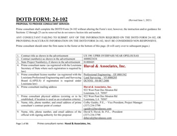
Bridge Software Institute - NewsletterIssue #23Page 5FALL2018Index TableExclusion of Skin Friction for Embedded Casing Lengthsof Drilled ShaftsWhat’s New at BSIPage 2FB-MultiPier v5.4ProgramEnhancementsAn option has been added to the “Analysis Settings” window, Fig. 2, which allowsengineers to exclude soil skin friction from the embedded portions of drilled shafts fittedwith casings.Page 2Modeling TipsPage 7Technical SupportPage 8Program StatusPage 9FB-MultiPier v5.4FB-Deep v2.05Atlas v7.0Figure 2. Exclude Skin Friction for Embedded Casings option on Analysis Settings pageContact BSIPage 10Bridge Software InstituteUniversity of FloridaPO Box 116580Gainesville, FL 32611Online: bsi.ce.ufl.eduEmail: bsi@ce.ufl.eduFax: (352) 392-3697The following example illustrates the process of excluding soil skin friction resistancealong the embedded casing length of drilled shafts. Consider the hammerhead pierdepicted in Fig. 3. This substructure consists of a single drilled shaft fitted with casingfrom the bottom of the sand layer up to the water surface elevation. A column extendsconcentrically up beyond the drilled shaft, and the overall substructure is topped withtapered pier cap cantilevers. In this example, the substructure is subjected to self-weightloading.
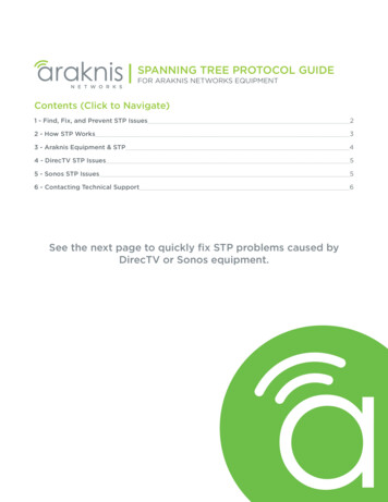
Bridge Software Institute - NewsletterIssue #23Page 6FALL2018Index TableWhat’s New at BSIPage 2FB-MultiPier v5.4ProgramEnhancementsPage 2Modeling TipsPage 7Technical SupportPage 8Program StatusPage 9FB-MultiPier v5.4FB-Deep v2.05Atlas v7.0Contact BSIPage 10Bridge Software InstituteUniversity of FloridaPO Box 116580Gainesville, FL 32611Online: bsi.ce.ufl.eduEmail: bsi@ce.ufl.eduFax: (352) 392-3697Figure 3. Elevation view of hammerhead pier configurationAfter enabling the exclusion of skin friction for embedded casing lengths (recall Fig. 2),the Pile Force Results windows can be accessed to review reactions along the shaft. Thiscan be done by clicking the Pile Force Results button (Fig. 4, top), selecting the shaft inthe Pile Plan View window, and checking the “Soil Reaction Zp (kips)” checkbox. Theseactions will open the Printable Forces dialog (Fig. 4, bottom), which tabulates vertical soilreactions along the shaft. As expected, only a nominal soil reaction is generated alongthe embedded casing length (elevations -18ft to -56ft).
Bridge Software Institute - NewsletterIssue #23Page 7FALL2018Index TableWhat’s New at BSIPage 2FB-MultiPier v5.4ProgramEnhancementsPage 2Modeling TipsPage 7Technical SupportPage 8Program StatusPage 9FB-MultiPier v5.4FB-Deep v2.05Atlas v7.0Figure 4. Printable Forces dialog for Soil Reaction (Zp)Contact BSIPage 10Bridge Software InstituteUniversity of FloridaPO Box 116580Gainesville, FL 32611Online: bsi.ce.ufl.eduEmail: bsi@ce.ufl.eduFax: (352) 392-3697Modeling TipsHammerhead PiersThe hammerhead pier from Fig. 3 can be easily modeled in FB-MultiPier. A tip forcreating such a model with a single pile or shaft support is simply to supply a 1 x 1 gridline mesh from within the Pile Cap model data window (Fig. 5), which indicates to theprogram that no pile cap is present within the substructure. Further, for this type ofmodel, the pile and column are directly connected end-to-end.
Bridge Software Institute - NewsletterIssue #23Page 8FALL2018Index TableWhat’s New at BSIPage 2FB-MultiPier v5.4ProgramEnhancementsPage 2Figure 5. Pile cap mesh discretization of 1x1 for use in modeling hammerhead configurationsModeling TipsPage 7Technical SupportIn FB-MultiPier, the pier cap can also be sloped or tapered from within the Pier page.For example, the pier cap cantilever for the example configuration from Fig. 3 is taperedacross 19 incrementsPage 8Program StatusPage 9FB-MultiPier v5.4FB-Deep v2.05Atlas v7.0Contact BSIPage 10Bridge Software InstituteUniversity of FloridaPO Box 116580Gainesville, FL 32611Online: bsi.ce.ufl.eduEmail: bsi@ce.ufl.eduFax: (352) 392-3697Technical SupportCary PetersonTechnical Support, Bridge Software InstituteLocation of model files: When running an analysis with FB-MultiPier, the input file shouldalways be located on the local machine, and not on a network server. If an input file islocated on a server, network latency can disrupt reading and writing of analysis files,and cause the program to crash. Thus, it is best practice to create a folder on the localmachine and save the input file to this location. Once the model has been analyzed,the input (.in) and output (.out) files can be copied back to the server location (forpermanent storage, or access by other engineers).Identifying the program version: To leverage all program features and revisions,engineers are encouraged to make use of the most currently available versions of BSIsoftware. To identify the current version of program installed on your computer, openthe program and go to Help - About to see the program version number.
Bridge Software Institute - NewsletterIssue #23Page 9FALL2018Index TableWhat’s New at BSIPage 2FB-MultiPier v5.4BSI Program StatusFB-MultiPier v5.4Download a FREE demo today!Released November 2018 - Continuing Development - Technical SupportAvailableProgramEnhancementsPage 2Modeling TipsPage 7FB-MultiPier allows for the modeling of bridges, bridge piers, pilebents, and other foundation structures. In addition to allowing formultiple load cases and AASHTO load combinations, FB-MultiPier isalso capable of performing dynamic analysis (time-history and RSA).For more information about FB-MultiPier, click here.Technical SupportPage 8FB-Deep v2.05Download a FREE demo today!Released January 2018 - Continuing Development - Technical Support AvailableProgram StatusPage 9FB-MultiPier v5.4FB-Deep v2.05Atlas v7.0Contact BSIPage 10Bridge Software InstituteUniversity of FloridaPO Box 116580Gainesville, FL 32611Online: bsi.ce.ufl.eduEmail: bsi@ce.ufl.eduFax: (352) 392-3697FB-Deep is used to estimate the static axial capacity of drilled shaftsand driven piles. The methodology is based upon Federal HighwayAdministration (FHWA) reports. FB-Deep guides the user throughpile and shaft materials data, shape and dimensional inputs, soilproperties, and boring log info. For more information about FB-Deep,click here.Atlas v7.0Released June 2017 - Limited Web Support AvailableAtlas is a finite element analysis program that is used for the design/analysis of cable supported traffic signal systems. The Atlas programmodels dual cable supported systems including single-point, and twopoint attachments systems. For more information about Atlas, clickhere.
Bridge Software Institute - NewsletterIssue #23Page 10FALL2018Index TableWhat’s New at BSIPage 2FB-MultiPier v5.4ProgramEnhancementsContact BSIIf you need to contact BSI for any reason you can use any of the methods below:Online: bsi.ce.ufl.eduEmail: bsi@ce.ufl.eduFax: (352) 392-3697Page 2Mailing Address:Modeling TipsPage 7Technical SupportPage 8Program StatusPage 9FB-MultiPier v5.4FB-Deep v2.05Atlas v7.0Contact BSIPage 10Bridge Software InstituteUniversity of FloridaPO Box 116580Gainesville, FL 32611Online: bsi.ce.ufl.eduEmail: bsi@ce.ufl.eduFax: (352) 392-3697Bridge Software InstituteUniversity of FloridaPO Box 116580Gainesville, FL 32611
Please contact BSI at bsi@ce.ufl.edu with your ideas. Bridge Software Institute - Newsletter Page 1. FALL 2018 Issue 23 Index Table What's New at BSI Page 2 FB-MultiPier v5.4 Program . Journal of Geotechnical and Geoenvironmental Engineering, 139(4), 564- 576. Ismael, N. F. (1990). "Behavior of Laterally Loaded Bored Piles in Cemented .