Transcription
Introduction to X-rayFluorescence Analysis (XRF)Fundamental Principles, InstrumentationInnovation with IntegrityXRF
Bruker AXS is continually improving its products andreserves the right to change specifications without notice.Order No. DOC-M84-EXS001 V8. 2016 Bruker AXS.Bruker AXS GmbHKarlsruhe · GermanyPhone 49 721 5 09 97-0 49 721 5 09 97-56 54Faxinfo.baxs@bruker.comwww.bruker.com
Introduction to X-Ray Fluorescence Analysis (XRF)Table of ContentsIntroduction to X-ray FluorescenceAnalysis (XRF)Table of ContentsFundamental Principles . 1Electromagnetic Radiation, Photons .1The Origin of X-rays . 1Bohr's Atomic Model . 2Characteristic Radiation . 2Nomenclature . 3Generating the Characteristic Radiation .3X-ray Tubes, Bremsspektrum .4Tube Types, Generator . 5Side-window Tubes .5End-window Tubes .5Generator . 6Excitation of Characteristic Radiation in Sample Material . 6Absorption, the Mass Attenuation Coefficient . 7Layer Thickness, Saturation Thickness . 8Secondary Enhancement. 9Tube-Spectrum Scattering at the Sample Material . 9Rayleigh Scattering . 10Compton Scattering . 10Measuring X-rays . 10Detectors, Pulse Height Spectrum . 10Gas Proportional Counter . 10Scintillation Counters .11Pulse Height Analysis (PHA), Pulse Height Distribution . 12The Counter Plateau . 13Diffraction in Crystals . 14Interference . 14Diffraction . 15X-ray Diffraction from a Crystal Lattice, Bragg's Equation. 15Reflections of Higher Orders. 17Crystal Types . 18Dispersion, Line Separation . 19Standard Types, Multilayers . 20Special Crystals . 21Curved Crystals for Rowland Geometry . 25Instrumentation . 26Wavelength Dispersive X-ray Fluorescence Spectrometers . 26The Multichannel Spectrometer S8 LION . 26DOC-M84-EXX001 V8 – 10.2016i
Table of ContentsIntroduction to X-Ray Fluorescence Analysis (XRF)The Sequential Spectrometer S8 TIGER . 28The End-window Tube and the Generator . 29The Primary Beam Filter . 30Sample Cups, the Cup Aperture . 31The Vacuum Seal . 32Collimator Masks . 32Collimators, the Soller Slit . 32The Crystal Changer . 33The Flow Counter . 33The Scintillation Counter . 33Electronic Pulse Processing . 34The Discriminator . 34Main Amplifier, Sine Amplifier . 34Dead Time Correction . 34Line-shift Correction . 35Energy Dispersive XRF with the S2 PUMA . 36Basic Principles of the SDD Detectors . 37Energy Resolution . 39Spectral Artefacts in EDXRF . 40Escape Peaks . 40Sum Peaks . 40Diffraction Peaks . 41System Contamination Peaks . 41Appendix A . 42Supplementary Literature . 42Books. 42Tables . 43Journals . 43Appendix B . 44Sources of Standard Samples . 44Index . 47iiDOC-M84-EXX001 V8 – 10.2016
Introduction to X-Ray Fluorescence Analysis (XRF)Fundamental PrinciplesFundamental PrinciplesElectromagnetic Radiation, PhotonsFrom a physical point of view, X-rays are of the same nature as visible light. Visible light can bedescribed as electromagnetic wave radiation whose variety of colors (e.g. the colors of the rainbow)we interpret as different wavelengths. The wavelengths of electromagnetic radiation reach from thekilometer range of radio waves up to the picometer range (10-12 m) of hard gamma radiation (Tab. 1).Tab. 1:Energy and wavelength ranges of electromagnetic radiation.Energy range (keV)Wavelength rangeName 10-7cm to kmRadio waves (short, medium, long waves) 10-3µm to cmMicrowaves 10-3µm to mmInfrared0.0017 – 0.0033380 to 750 nmVisible light0.0033 – 0.110 to 380 nmUltraviolet0.11 – 1000.01 to 12 nmX-rays10 – 50000.0002 to 0.12 nmGamma radiationIn the following text, the unit nanometer (nm 10-9 m) is used for the wavelength, ( Lambda), andthe unit kiloelectronvolts (keV) for energy, E.CommentIn literature the unit Angström (Å) is often stated for the wavelength:1 Å 0.1 nm 10-10 mThe following relationship (conversion formula) exists between the units E (keV) and (nm):E ( keV ) 1 . 24 ( nm )or (nm) 1.24E (keV )The X-ray fluorescence analysis records the following range of energy or wavelengths:E 0.11 - 60 keV 11.3 – 0.02 nmApart from the wave properties, light also has the properties of particles. This is expressed by the term”photon”. In the following we will be using the term photons or X-ray photons for this.The radiation intensity is the number of X-ray photons that are emitted or measured per unit of time.We use the number of X-ray photons measured per second, cps ( counts per second) or kCps ( kilocounts per second) as the unit of intensity.The Origin of X-raysElectromagnetic radiation can occur whenever electrically charged particles, particularly electrons,lose energy as a result of a change in their state of motion, e.g., upon deceleration, changing directionor moving to a lower energy level in the atomic shell. The deceleration of electrons and the transitionfrom an energy level in the atomic shell to a lower one play an important part in the creation of X-raysin the field of X-ray analysis. To understand the processes in the atomic shell we must take a look atthe Bohr's atomic model.DOC-M84-EXX001 V8 – 10.20161
Fundamental PrinciplesIntroduction to X-Ray Fluorescence Analysis (XRF)Bohr's Atomic ModelBohr's atomic model describes the structure of an atom as an atomic nucleus surrounded by electronshells (Fig. 1):Fig. 1:Bohr's atomic model, shell model.The positively charged nucleus is surrounded by electrons that move within defined areas (”shells”).The differences in the strength of the electrons‘ bonds to the atomic nucleus are very clear dependingon the area or level they occupy, i.e. they vary in their energy. When we talk about this we refer toenergy levels or energy shells. This means: A clearly defined minimum amount of energy is required torelease an electron of the innermost shell from the atom. To release an electron of the secondinnermost shell from the atom, a clearly defined minimum amount of energy is required that is lowerthan that needed to release an innermost electron. An electron’s bond to an atom is weaker the furtheraway it is from the atom’s nucleus. The minimum amount of energy required releasing an electronfrom the atom, and thus the energy with which it is bound to the atom, is also referred to as thebinding energy of the electron to the atom.The binding energy of an electron in an atom is established mainly by determining the incident. It is forthis reason that the term absorption edge is very often found in literature:Energy level binding energy absorption edgeThe individual shells are labeled with the letters K, L, M, N .; the innermost shell being the K-shell,the second innermost the L-shell etc. The K-shell is occupied by 2 electrons. The L-shell has threesub-levels and can contain up to a total of 8 electrons. The M-shell has five sub-levels and can containup to 18 electrons.Characteristic RadiationEvery element is clearly defined by its atomic number Z in the periodic system of elements or by thenumber of its electrons in a neutral state. The binding energies or the energy levels in every elementare different and characteristic for every element as a result of the varying number of electrons(negative charges) or the number Z of the positive charges in the atomic nucleus ( atomic number).If an electron of an inner shell is now separated from the atom by the irradiation of energy, an electronfrom a higher shell falls into this resultant “hole” which releases an amount of energy equivalent to thedifference between the energy levels involved.The energy being released can be either be emitted in the form of an X-ray or be transferred toanother atomic shell electron (Auger effect). The probability of an X-ray resulting from this process is2DOC-M84-EXX001 V8 – 10.2016
Introduction to X-Ray Fluorescence Analysis (XRF)Fundamental Principlescalled the fluorescence yield . This depends on the element’s atomic number and the shell in whichthe “hole” occurred. is very low for light elements (approx. 10-4 for boron) and almost reaches avalue of 1 for the K-shell of heavier elements (e.g. uranium).However, decisive is that the energy or wavelength of the X-ray is very characteristic for the elementfrom which it is emitted; such radiation is called characteristic X-rays.This provides the basis for determining chemical elements with the aid of X-ray fluorescenceanalysis.NomenclatureThe energy of an X-ray corresponds to the difference in energy of the energy levels concerned. Kradiation is the term given to the radiation released when replenishing the K-shell, L-radiation to thatreleased when replenishing the L-shell etc. (Fig. 2).Also needed for the full labeling of the emitted X-ray line is the information telling us which shell theelectron filling the “hole” comes from. The Greek letters , , , . are used for this with the numbering1, 2, 3, . to differentiate between the various shells and sub-levels.Fig. 2:X-ray line labeling.Examples:Electron from sub-level LIII to the K-shell (K )K K Electron from sublevel LII to the K-shell (K )K if neither line is resolved by the spectrometer: K Electron from sublevel M to the K-shell (K 1)Electron from sublevel M to the L-shell (L )K 1L Generating the Characteristic RadiationThe purpose of X-ray fluorescence is to determine chemical elements both qualitatively andquantitatively by measuring their characteristic radiation. To do this, the chemical elements in asample must be caused emit X-rays. As characteristic X-rays only arise in the transition of atomic shellelectrons to lower, vacant energy levels of the atom, a method must be applied that is suitable forreleasing electrons from the innermost shell of an atom. This involves adding to the inner electronsamounts of energy that are higher than the energy bonding them to the atom.DOC-M84-EXX001 V8 – 10.20163
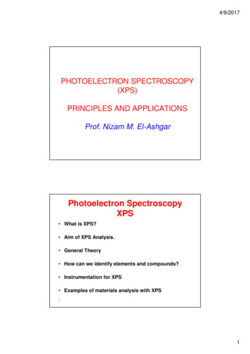
Fundamental PrinciplesIntroduction to X-Ray Fluorescence Analysis (XRF)This can be done in a number ways: Irradiation using elementary particles of sufficient energy (electrons, protons, -particles, .) thattransfer the energy necessary for release to the atomic shell electrons during collision processes Irradiation using x- or gamma rays from radionuclides Irradiation using X-rays from an X-ray tubeUsing an X-ray tube here proves to be the technically most straightforward and, from the point of viewof radiation protection, the safest solution (an X-ray tube can be switched off, a radionuclide cannot).X-ray Tubes, BremsspektrumIn an X-ray tube, electrons are accelerated in an electrical field and shot against a target materialwhere they are decelerated. The technical means of achieving this is to apply high voltage between aheated cathode (e.g. a filament) and a suitable anode material. Electrons emanate from the heatedcathode material and are accelerated towards the anode by the applied high voltage. There they strikethe anode material and lose their energy through deceleration. Only a small proportion of their energyloss (approx. 1-2 %, depending on the anode material) is radiated in the form of X-rays. The greatestamount of energy contributes to heating up the anode material. Consequently the anode has to becooled which is achieved by connection to a water-cooling system.The proportion of the electron energy loss emitted in the form of an X-ray can be between zero andthe maximum energy that the electron has acquired as a result of the acceleration in the electricalfield. If 30 kV are applied between the anode and cathode, the electrons acquire 30 keV from passingthrough this voltage (kiloelectron volts) (Definition: 1 eV the energy that an electron acquires whenpassing through a potential of 1 Volt).A maximum X-ray energy of 30 keV can be acquired from deceleration in the anode material, i.e. thedistribution of the energies of numerous X-rays is between zero and the maximum energy. If theintensity of this type of X-ray is applied depending on the energy, the result is the Bremsspektrum ( continuum) of the tube.Fig. 3:4A Bremsspektrum ( continuum) with characteristic radiation of the anode material.DOC-M84-EXX001 V8 – 10.2016
Introduction to X-Ray Fluorescence Analysis (XRF)Fundamental PrinciplesIn addition to the Bremsspektrum, an X-ray tube of course emits the characteristic radiation of theanode material as well which is of major importance for the X-ray fluorescence analysis (Fig. 3).Tube Types, GeneratorAll X-ray tubes work on the same principle: accelerating electrons in an electrical field anddecelerating them in a suitable anode material. The region of the electron beam in which this takesplace must be evacuated in order to prevent collisions with gas molecules. Hence there is a vacuumwithin the housing. The X-rays escape from the housing at a special point that is particularlytransparent with a thin beryllium window.The main differences between tube types are in the polarity of the anode and cathode and thearrangement of the exit window. The two most significant types are the end-window tubes and theside-window tubes. The side-window tube design is the historical design, whereas today for modernXRF- instruments only end-window tubes are used due to the higher efficiency.Side-window TubesIn the past side window tubes were used for XRF instrumentation. In side-window tubes, a negativehigh voltage is applied to the cathode. The electrons emanate from the heated cathode and areaccelerated in the direction of the anode. The anode is set on zero voltage and thus has no differencein potential to the surrounding housing material and the laterally mounted beryllium exit window(Fig. 4).Cooling water for the anodeAnode Electron beamX-rayFig. 4:Beryllium window,e.g. 75 mThe principle of the side-window tube.For physical reasons, a proportion of the electrons are always scattered on the surface of the anode.The extent to which these back-scattering electrons arise depends, amongst other factors, on theanode material and can be as much as 40 %. In the side-window tube, these back-scattering electronscontribute to the heating up of the surrounding material, especially the exit window. As aconsequence, the exit window must withstand high levels of thermal stress any cannot be selectedwith just any thickness. The minimum usable thickness of a beryllium window for side-window tubes is300 µm. This causes an excessively high absorption of the low-energy characteristic L radiation of theanode material in the exit window and thus a restriction of the excitation of lighter elements in asample.End-window TubesModern XRF instrumentation is using due to the better efficiency means higher primary intensity endwindow X-ray tubes. The distinguishing feature of the end-window tubes is that the anode has apositive high voltage and the beryllium exit window is located on the front end of the housing (Fig. 5).DOC-M84-EXX001 V8 – 10.20165
Fundamental PrinciplesIntroduction to X-Ray Fluorescence Analysis (XRF)Electron beamCathode (annular, tungsten)X-rayCooling water for the anode75 m Berylliumwindow (example)Fig. 5:AnodeThe principle of the end-window tube.The cathode is set around the anode in a ring (angular cathode) and is set at zero voltage. Theelectrons emanate from the heated cathode and are accelerated towards the electrical field lines onthe anode. Due to the fact that there is a difference in potential between the positively charged anodeand the surrounding material, including the beryllium window, the back-scattering electrons are guidedback to the anode and thus do not contribute to the rise in the exit window’s temperature. Theberyllium window remains “cold” and can therefore be thinner than in the side-window tube. Windowsare typically used with a thickness of 75 µm, older design will have thicknesses of about 125 µm.Actually the tube window thicknesses become thinner to 50 µm. This provides a prerequisite forexciting light elements with the characteristic L radiation of the anode material (e.g. rhodium).Due to the high voltage applied, non-conductive, de-ionized water must be used for cooling.Instruments with end-window tubes are therefore equipped with a closed, internal circulation systemcontaining de-ionized water that cools the tube head as well.End-window tubes have been implemented by all renowned manufacturers of wavelength dispersiveX-ray fluorescence spectrometers since the early 80‘s.GeneratorThe current, the high voltage for the X-ray tubes and the heating current for the cathode are producedin the X-ray generator. The generators available today supply a maximum tube current of 150 mA anda maximum high voltage of 60 kV at a maximum output of 4 kW, i.e. current and voltage must beselected in such a way that 4 kW is not exceeded. The architecture of modern control electronics andsoftware ensures that damage to the tube resulting from maladjustment is impossible. The reason forrestricting the maximum excitation power to 1 kW is that cooling with external coolant can bedispensed with which simplifies installation requirements.Excitation of Characteristic Radiation in SampleMaterialThe Bremsstrahlung and the characteristic radiation of the X-ray tube’s anode material are used toexcite the characteristic radiation of the elements in the sample material. It is very important toknow that a chemical element in the sample can only be made to emit X-rays when the energy of theincident X-ray photons is higher than the binding energy (absorption edge) of the element’s innerelectrons. If the sample is irradiated with a tube high-voltage of e.g. 20 kV, the maximum energy of thephotons emitted from the tube is 20 keV. Hence, it is impossible, for example, to excite the K radiationof the elements that have an atomic number Z 43 as their K binding energy is greater than 20 keV.Excitation of the K radiation of heavier elements is achieved with a generator setting of 60 kV.All renowned manufacturers use rhodium (Rh) as the standard anode material as the characteristicenergies of this element are simultaneously suitable for exciting both heavy and light elements.Energies and wavelengths of rhodium’s characteristic lines, and the heaviest element that can beexcited with the appropriate line in each case, are listed in Tab. 2.6DOC-M84-EXX001 V8 – 10.2016
Introduction to X-Ray Fluorescence Analysis (XRF)Tab. 2:Fundamental PrinciplesRhodium’s characteristic lines.LineEnergyWavelengthHeaviest elementRh Ka120.214 keV0.0613 nmMolybdenum (Mo)Rh Ka220.072 keV0.0617 nmMolybdenum (Mo)Rh Ka122.721 keV0.0546 nmRuthenium (Ru)Rh La1,22.694 keV0.4601 nmSulphur (S)Rh La12.834 keV0.4374 nmChlorine (Cl)The following can be extracted from Tab. 2: The K lines of the heavy elements from rhodium to tantalum (Ta) can, on principle, only be excitedwith the Bremsstrahlung of the rhodium tube as the energy of the rhodium lines is insufficient todo it. A generator setting of 60 kV is recommended for such cases. The elements as far as molybdenum are excited by the Rh K radiation. The Rh-K 1 radiation caneven excite the element ruthenium but is of lower intensity than the K-alpha radiation. The light elements up to sulphur are excited very effectively by the Rh L radiation. The Rh-L 1 radiation can excite the element chlorine but is of a lower intensity. Decisive for theavailable intensity of the Rh L radiation is the thickness of the tube’s beryllium exit window.Instead of rhodium, other elements can be used as an anode material for special applications.Tungsten (W) and gold (Au) are particularly suitable for exciting heavier elements with theBremsspektrum. Chromium (Cr) was often used in side-window tubes for exciting lighter elements.Molybdenum (Mo) was frequently used for the interference-free measurement of rhodium and, forexample, cadmium.The use of the rhodium end-window tube as a “universal tube” is justified as the light elements can beexcited far more effectively with the Rh L radiation than with the K radiation of a chromium anode.Moreover, instrument technology is so advanced nowadays that measuring rhodium itself (orcadmium) presents no problem. Please also refer to the technique of the primary beam filter, page 30.Absorption, the Mass Attenuation CoefficientPassing through matter weakens the intensity of X-rays. The degree of this weakening depends onboth the radiation energy and the chemical composition of the absorbing material (e.g. the sample).Heavier elements absorb better than light ones: 1 mm of lead absorbs practically all of the higherenergy radiation occurring during X-ray fluorescence; 1 mm of polypropylene (hydrocarbon) is more orless permeable to X-rays. Low-energy X-ray photons are absorbed more readily than photons withhigher energy ( short wavelengths): the photons emitted by the element boron, for example, have avery low energy of 0.185 keV ( 67 nm) and are practically completely absorbed by even 6 µm ofpolypropylene foil.If an X-ray with photons of energy E and an intensity of Io pass through a layer of material, e.g., 1 mmsheet of pure iron (Fe), the ray emerging from behind the iron layer will only be left with the intensityI Io as a result of the absorption. The relationship between I and Io after the transition through thelayer thickness x is described by the law of absorption:I I 0 e xµ linear absorption coefficientThe linear absorption coefficient has the dimension [1/cm] and is dependent on the energy or thewavelength of the X-ray photons and the special density ρ (in [g/cm3]) of the material that was passedthrough.If the iron sheet in the above example is replaced by a 1 mm layer of iron powder, the absorption isless because the density of the absorber is lower. Therefore, it is not the linear absorption coefficientthat is specific to the absorptive properties of the element iron, but the coefficient applicable to thedensity of the material that was passed throughDOC-M84-EXX001 V8 – 10.20167
Fundamental PrinciplesIntroduction to X-Ray Fluorescence Analysis (XRF) / mass attenuation coefficientThe mass attenuation coefficient has the dimension [cm2/g] and only depends on the atomic numberof the absorber element and the energy, or wavelength, of the X-ray photons.Fig. 6 illustrates the schematic progression of the mass attenuation coefficients depending on theenergy or wavelength.Fig. 6:Schematic progression of the mass attenuation coefficient of energy or wavelength.Fig. 6 supplies the following: The overall progression of the coefficient decreases as energy increases, i.e. the higher theenergy of the X-ray photons, the less they are absorbed. The rapid changes in the mass attenuation coefficient reveal the binding energies of the electronsin the appropriate shells. If an X-ray photon has a level of energy that is equivalent to the bindingenergy of an atomic shell electron in an appropriate shell, it is then able to transfer all its energy tothis electron and displace it from the atom. In this case, absorption increases sharply. Photonswhose energy is only slightly below the absorption edge are absorbed far less readily.Exampl
of radiation protection, the safest solution (an X-ray tube can be switched off, a radionuclide cannot). X-ray Tubes, Bremsspektrum In an X-ray tube, electrons are accelerated in an electrical field and shot against a target material where they are decelerated. The technical means of achieving this is to apply high voltage between a


![[AWS Black Belt Online Seminar] AWS X-Ray](/img/17/20200526-blackbelt-x-ray.jpg)