Transcription
CHEST X-RAY TRAINING MANUAL FOR HIV AND TB CLINICIANSTom Heller, MD
Lighthouse Chest X-ray Training Manual for HIV and TB CliniciansTom Heller, MDSpecialist in Internal Medicine and Infectious Diseases (Germany)Clinical AdvisorLighthouse ClinicLilongwe, Malawi
To my daughter, Yael, who knows a lot about the importance of sight and vision.‘It is only with the heart that one can see rightly; what is essential is invisible to the eye.’—Antoine de Saint-Exupery
DisclaimerEvery attempt has been made to ensure that the information in this casebook is accurate and correct. The author andpublishers accept no responsibility for any loss or damage that may arise out of the reliance of any person upon any of theinformation provided in the book, nor is responsibility accepted for any loss or damage sustained as a result of the use ofthe information contained herein.When in doubt, seek the assistance of a more senior colleague, or, when further information is required concerning drugindications or dosage, consult the National Drug Formulary, the current pharmaceutical package inserts, or the relevantpharmaceutical company.
Table of tion. vii1. X-ray Physics. 12. Image Quality.23. Normal Chest Anatomy.44. Systematic Assessment of a Chest X-ray.95. Pathological Patterns of the Lungs. 116. Pleural Effusion, Pneumothorax, and Other Pleural Changes. 177. Tuberculosis.208. Pneumonia.249. Pneumocystis Pneumonia.2610. Kaposi Sarcoma. 2711. Cardiomegaly.2812. Pericardial TB.2913. Dilated Cardiomyopathy.3014. Mitral Valve Changes and Rheumatic Heart Disease. 3115. Cor Pulmonale.3216. Cardiovascular Syphilis.33Appendix 1. Bone and Joint Tuberculosis on X-rays.34Appendix 2. Case Quizzes. 37Cases 1–20.38–77Image Sources.78Lighthouse Chext X-ray Training Manual for HIV and TB CliniciansIndex.79
AcknowledgementsThe idea for this manual stems from several practical CXR trainings held at the Lighthouse Clinics in Malawi.These were held not just for clinical officers, but also for medical students and other interested parties. As Ideveloped these tranings, the Radiographic Manifestations of Tuberculosis: A Primer for Clinicians teachingmaterial published by the Curry International Tuberculosis Center, UCSF (www.currytbcenter.ucsf.edu) provedto be an invaluable reference, one that I highly recommend.The diagnosis of TB in patients at various levels of immunosuppression is an important skill for all clinicians; theLighthouse Clinic is a WHO-recognised Centre of Excellence for HIV care. I would like to thank the growing teamof Lighthouse clinicians who care for our patients, participate in trainings, do their best to diagnose opportunisticinfections, and share CXR images to get telemedical support for their decisions.I would further like to thank Dr Ashlyn Sakona (Dept of Infectious Diseases, UCLA, Los Angeles), and DrsElizabeth Joekes and Jehan Ghany (Dept of Radiology, Liverpool University Hospitals) for reading through partsof this radiological text in English written by a non-English non-radiologist. The improvements are to their credit;the remaining faults are mine.I would like to thank Kevin J. O’Conner in Seattle for his great work on the artwork, layout, and typesetting of thismanual—he did a tremendous job handling all my requests.I would further like to thank Lighthouse management, in particular Executive Director Prof. Sam Phiri; andI-TECH Malawi management, in particular Country Director Dr Yusuf Babaye, for their support. I would alsolike to acknowledge our funding organisation, PEPFAR through CDC Malawi.Finally, I would like to thank my wife, Dr Claudia Wallrauch, just for joining me—there and back again.Lighthouse Chext X-ray Training Manual for HIV and TB Clinicians—Tom Heller, MDv
AbbreviationsAFBAcid-fast bacilliARDSAcute respiratory distress ULLVMDRMTBNSAIDOIPAPCPPCRPRPTBRHDLighthouse Chext X-ray Training Manual for HIV and TB erior, anterior to posteriorAntiretroviral therapyBlood pressureCommunity-acquired pneumoniaCenters for Disease Control and PreventionCardiomyopathyChronic obstructive pulmonary diseaseCardiothoracic ratioChest X-rayImmune reconstitution inflammatory syndromeKaposi sarcomaKaposi sarcoma-associated herpes virusLymph node(s)Left lower lobeLeft upper lobeLeft ventricle, left ventricularMultidrug resistance, multidrug-resistantMycobacterium tuberculosisNon-steroidal anti-inflammatory drugOpportunistic infectionPosterior-anterior, posterior-to-anteriorPneumocystis pneumoniaPolymerase chain reactionPulse ratePulmonary TBRheumatic heart diseaseRifampin, isoniazid, pyrazinamide, ethambutol (TB drug regimen)Rifampin; in GeneXpert, resistance to rifampinRight lower lobeRight middle lobeRespiration rate, respiratory rateRight upper lobeTuberculosisTuberculosis-immune reconstitution inflammatory ir (ART drugs)TMPTrimethoprim (component of cotrimoxazole)TDLVLWBCWHOviTuberculosis destroyed lungViral loadWhite blood countWorld Health Organization
IntroductionChest radiography, or chest X-ray (CXR) is an essentialtool for early detection of tuberculosis (TB), and thereforefundamental to achieving the targets set out in WHO’sEnd TB Strategy.Lighthouse Chext X-ray Training Manual for HIV and TB Clinicians—Chest Radiography in Tuberculosis Detection, WHO2016. (https://www.who.int/tb/publications/RadiographyTB factsheet.pdf)In its 2016 fact sheet, Chest Radiography in Tuberculosis Detection, the World Health Organization (WHO)recognised the chest x-ray as an essential technology.According to WHO, it is a sensitive tool for screeningfor active TB, helps to rule out active TB before treating latent TB infection, can improve the efficiency ofGene Xpert MTB/RIF testing, and can help diagnose TBamong people living with HIV.Although instruments are necessary to producethe images, the medical gaze is required to recognisethe findings. The ability of x-rays to reveal the typicalchanges of tuberculosis of the lungs is long known. Thediscovery of x-rays in 1895 by Wilhelm Conrad Roentgen(1845-1923), a professor at Würzburg University in Germany, was immediately followed by their use to visualiseTB changes.In what is probably one of the first textbooks on radiology, Die röntgenologische Diagnostik der Erkrankungender Brusteingeweide [The Roentgenologic Diagnosis ofDiseases of the Thoracic Organs], published in Viennain 1901 by Guido Holzknecht (1872-1931), more than 15pages are dedicated to the disease; the book containsnumerous images of TB patients. It describes the apicalchanges with cavities (Spitzenkartarrh, Figure A) thatwere considered typical TB for many years afterwards,and tuberculous lymphadenopathy (Lymphdrüsentumor,Figure B), which would historically have been consideredatypical TB.Because effective drug therapy for TB was not developed until half a century later, the book also containsan image of the unfortunate end-stage TB—a shrinking chronic inflammation with destruction of the lung, apicture we sadly still see in our patients, and which wewould today describe as tuberculosis destroyed lung(Figure C).We have come a long way with respect to technologyand image quality, but the underlying principles havestayed the same. It is therefore essential for all clinicians challenged with diagnosing tuberculosis—whetherin HIV-positive or HIV-negative patients—to know itsradiological features, understand their correlation withdisease stages, distinguish them from the most common differential diagnoses, and use them to initiate ade quate treatment of a curable disease that still causesmany unnecessary deaths worldwide. We hope that thismanual and the many sample images shown can helpin this cause.Figure A. Using an inverse view of radiographs (with the bones blackinstead of white), we can see in this CXR of a 20 year old seamstress‘strand–forming shadows in the right upper lobe with a bright centrerepresenting a certain cavity’. All these are features of ‘typical’ TB.(Holzknecht 1901)Figure B. The left hilum shows ‘a curved outline of a shadowing mass’due to tuberculous lymphadenopathy—a feature of ‘atypical’ TB. (Holzknecht 1901)Figure C. Here the features of end-stage TB are clearly visible andwell defined. On the left side there are wide intercostal spaces due tohyperinflation of the lung; ‘the right lung field is dense due to infiltrationsand shrinking, the whole mediastinum is pulled to the right The heartis fully dislocated into the right thorax.’ (Holzknecht 1901)vii
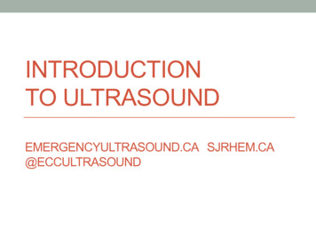
1. X-ray PhysicsTo understand a chest x-ray (CXR), we need a basic un- Tissue Densityderstanding of x-ray physics and how an image is crea The density of the different tissues seen on a CXR varted. For our purposes, some basic facts will be sufficient. ies substantially; therefore absorption also varies. TheThe two main components of an x-ray machine are denser the tissue, the more energy it absorbs, and thethe x-ray source and the x-ray detector. The source is whiter it appears on the radiograph. Tissue that is lesscalled an x-ray tube; x-rays are emitted from this tube dense absorbs less energy, so the corresponding partswhen the machine is activated. The rays pass through an of the image are blacker.object, such as the patient who is positioned between thesource and the detector. The detector is called an x-raycassette. Historically, the cassette contained film, whichafter exposure was developed and could then be vieweddirectly. Today many x-ray cassettes use electronic detectors that create digital images, which can be viewedon computer screens.A standard CXR is obtained using a fixed distance of180 cm between the tube and the cassette; the rays passthrough the patient from back to the front (this orientationis called posterior to anterior, or PA).If the patient is unable to stand, sometimes the cassette has to be placed under the back of the patient, whois now lying down; in this case, the rays pass from frontto back (anterior to posterior, or AP).AP images often have a different, usually lower quality.They may be distorted in three ways: The mediastinum and the heart are magnified, andappear too large.It is difficult for the patient to take a full breath inthis position.Rotation may be present.Therefore, whenever possible the x-ray technicianshould try to obtain a standard PA image.When x-ray photons pass through the body, they canbasically interact with the body in three ways:Lighthouse Chext X-ray Training Manual for HIV and TB Clinicians They may be absorbed completely: no energyreaches the film.They may pass unabsorbed: the full energy reaches the film.They may be partially absorbed and scattered:some of the energy reaches the film, but the restis lost along the way.Two factors contribute to the amount of absorption:the energy (strength) of the x-ray beam, and the densityof the structures it passes through.EnergyThe energy of a standard CXR is largely constant, andthus we do not need to discuss it further. However, it isimportant to know that x-ray technicians can change theenergy if they need to.1Figure 1. Correlation between energy absorption and CXR appearance.These differences in absorption between types of tissue mean that distinct structures can be visualised. Forexample, the heart and lungs have different densities:the heart is mainly soft tissue, whereas the lung is mainlyair. Accordingly, the denser tissue of the heart will absorbmore energy and appear whiter on the x-ray than theadjacent lung tissue. This difference allows us to see theinterface between lung and heart. That sharp line is alsocalled a silhouette.On the other hand, the diaphragm (including the liverand organs below) and heart tissue have very similardensities—both consist mainly of soft tissue. As a result,they will absorb similar amounts of energy, and appearsimilarly white on the resulting x-ray—that is, it will not beclear where one structure ends and the other begins. Because we cannot see an interface, there is no silhouette.Sometimes you expect to see a silhouette (for example, between heart and lung), but the sharp line isblurred—the silhouette begins to disappear. This happens when the density of the lung (normally air) becomesincreasingly similar to that of the heart (soft tissue). Thisis called the silhouette sign, which can be suggestive ofpneumonia or other consolidations. We will come backto this later.
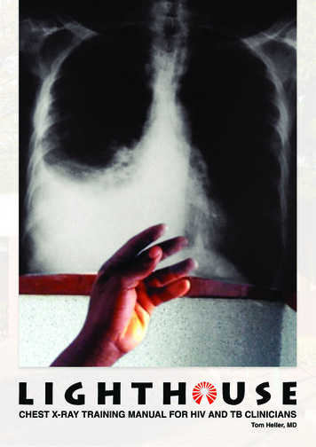
2. Image QualityThe first step in interpreting a CXR is to check five technical points relating to image quality: IdentityOrientationExposureInsirationRotationCXR, the lung structures may be difficult to assess, especially the central areas. Because the image has toomuch white, the hilum may seem enlarged and the intra pulmonary vessels too pronounced.IdentityIt is important to briefly verify that the x-ray image matches to the patient. In busy x-ray departments, it is easyfor films to get mixed up, so it is important to check thepatient name (which is, hopefully, printed) on the filmbefore examining it to ensure that you are making decisions for the correct patient.OrientationThe next step—small but relevant—is to check whichside is right and which is left. Usually the radiology technicians will put an L or R marker on the film to indicatethe side. Unfortunately, this is sometimes forgotten—inwhich case we cannot be sure what the proper orientation of the image is. The simple rule, ‘left is where theheart is’, often works—but is sometimes misleading. Forexample, if the patient has a situs inversus—a rare condition with a complete reverse orientation of the internalorgans—the heart will be on the right side. More often,previous chest disease may distort the anatomy, shiftingthe mediastinal structures so that orientation is less obvious, or even impossible to determine.Figure 3. On an underexposed CXR, the lungs appear too white; lungstructures may be difficult to assess, as they may be overshadowed.On the other hand, if the spine is too visible, theimage is overexposed or too hard (Figure 4). The imagewill seem too black, and you will not be able to see theblood vessels towards the periphery of the lung (also asign of over exposure—and a common error).Lighthouse Chext X-ray Training Manual for HIV and TB CliniciansExposureA properly exposed CXR (Figure 2) allows us to see thethoracic spine, and especially the thoracic intervertebraldisc spaces, faintly through the shadow of the heart. Theblood vessels in the lung should be visible up to at least2 to 3 cm from the lung periphery.Figure 4. On an overexposed CXR, the lungs appear too black.Smaller structures, such as nodules or faint infiltrates, can easilybe missed.InspirationThe CXR should be taken with deep inspiration. Posteriorly, nine or 10 ribs should be visible above thediaphragm to ensure inspiration is sufficient.Two problems can occur when inspiration is too shallow (eight or fewer ribs showing):Figure 2. Normal CXR, with the L marker (large arrow) identifying thepatient’s left side. Intervertebral disc spaces (small arrows) are faintlyvisible through the heart.If the spine becomes invisible, the image is underexposed or too soft (Figure 3). On an underexposed2 The cardiac diameter may appear enlarged.The failure to distend the lungs fully will causecrowding of vessels, especially around the hilumand at the lung bases. This may give the appearance of a basal lung infection or vascular congestion.
When 11 or more posterior ribs are visible, lung vol- Rotationume is considered enlarged. This can be due to emphy- The patient is well positioned if the medial end of eachsema or chronic obstructive lung disease, which causes clavicle is the same distance (equidistant) from the cenhyperinflation, often seen with a flattened diaphragm. tre of the vertebral bodies (spinous processes). Whenone of the clavicles is further away from the centre thanthe other, rotation is present.Rotation is a common cause of one lung appearingblacker than the other. Also, on a rotated CXR, variousstructures can be projected towards the right or left side.This can cause the following diagnostic problems: Rotation to the right may project the upper partof the mediastinum—the superior vena cava andother vessels not usually prominent—to the right.This can mimic a mediastinal mass in the right upper zone.Rotation to the left may shift the aortic arch andthe silhouette of the heart to the left, making bothappear enlarged.Figure 5. A good quality CXR, done with deep inspiration and withoutrotation. The posterior parts of ten ribs (indicated by the numbers)are visible above the diaphragm. The medial ends of the clavicles areequidistant from the spinous processes.Lighthouse Chext X-ray Training Manual for HIV and TB CliniciansFigure 8. CXR rotated to the left. The aortic arch (arrowheads) is veryprominent and the left border of the heart appears enlarged (arrows).Figure 6. A poorer quality CXR, done with shallower inspiration. Thecardiac diameter seems larger and vessels are crowded especiallyaround the hilum (arrowheads).Figure 7. CXR with hyperinflated lungs due to emphysema (12 ribs arevisible). Note that the cardiac shadow seems to almost not touch thediaphragm. The diaphragms are very low, with the costophrenic anglescut off of the image and a fla t shape (concave on the lateral image;see arrows).3
3. Normal Chest AnatomyLighthouse Chext X-ray Training Manual for HIV and TB CliniciansFigure 9. Normal CXR with posterior–anterior view.To identify pathologies, one needs to know what is normal. In this chapter we will look at the structures as theyappear on a normal CXR. Figure 9 above shows an example of a normal CXR; this will serve as our referenceimage.Ribcage and Chest WallAlthough the CXR is not the ideal method for looking atbony structures, many bones can be seen on a CXR, sowe should be aware of the anatomy.Each rib is seen twice on the CXR. The anterior partin front is usually more vertical and seems to run downward. Closer to the sternum, the ribs become cartilageand thus are usually not visible; the sternum is also notusually visible. In the back, the dorsal part of the rib ismore horizontal, and is connected to the thoracic verte brae. It is worthwhile to quickly check the ribs for anyvisible fractures or tumours.In the upper part of the sternum, the two claviclesproject outwards and connect to the scapula. It is worthchecking these as well, both for fractures and for symmetry.The two scapulae deserve an extra word. Usually,they should be rotated out of the image so that they donot project on the lung fields, but are seen beside thethorax (as in Figure 9). If this is overlooked, or the patientis unable to rotate the arms, the scapulae may create extra lines and extra opacities that need to be consideredto avoid confusion (for example, with a pneumothorax).4The muscles, tendons, and fat of the chest wall allhave a similar density, and thus are usually not visible.Nevertheless, they are there; if there are major asymme t ries—for example, a very strong pectoral muscle on oneside—they may absorb extra energy, causing one lungto appear whiter than the other.Figure 10. Normal CXR: bony structures of the thorax.In female patients, and in male patients with gynaecomastia, breast shadows can often be seen. It is worthidentifying these shadows to avoid confusion with pathological findings.
zone, the middle third is the mid zone, and the lowerthird is the lower zone.Figure 11. Normal CXR: female patient with symmetrical breastshadows.DiaphragmThe two domes of the diaphragm are usually well defined, because the soft tissues below the diaphragm inthe abdomen have a different density than the air in thelung above. The liver is located under the right hemi diaphragm; this side is normally slightly higher than theleft hemidiaphragm. Under the left hemidiaphragm, abubble of gas in the stomach or gas in the bowels canoften be seen. It is worth briefly checking the gas distribution below the diaphragm, as free air suggesting aperforation in the bowels may sometimes be unexpectedly found on a CXR.PleuraLighthouse Chext X-ray Training Manual for HIV and TB CliniciansThe pleura is the fine serous membrane that folds backon itself to form the two-layered pleural cavity. The outerpleura (parietal pleura) is attached to the chest wall. Theinner pleura (visceral pleura) covers the lungs. Betweenthe two layers is a small amount of lubricating fluid toprevent friction during the respiratory cycle. Usually, thepleura is not visible on the CXR, as it is too thin. To determine whether there is extra fluid collected in the pleuralcavity, it is best to look at the costophrenic angle, whichis normally sharp.Figure 13. Normal CXR: approximate location of the lung zones.Hila and MediastinumBoth lungs have a central part called the hilum at theroot of the lung, where the blood vessels and bronchienter into the lungs. Ninety-nine percent (99%) of thehilar shadow is caused by vessels, particularly the pulmonary arteries and, to a lesser extent, the pulmonaryveins. In a normal CXR, there is only a minimal con tribution from fat, lymph nodes, and bronchial walls. Theleft hilum is usually slightly higher than the right. Thisis because the left pulmonary artery passes over theleft main bronchus, whereas the right pulmonary arterypasses in front of the right main bronchus. With respectto hilar density and size, there is wide variation amongnormal individuals. They should be similar on both sides.In the hila, there are also bronchopulmonary lymphnodes. In a healthy individual, these are small and notvisible. When the lymph nodes are enlarged, though, thehila can become enlarged.The heart and the large vessels are loca ted in themedia stinum. This is the central area of soft tissue seenas white on the CXR. The main vessels are the aortaand the superior vena cava with their branches. Theinferior vena cava can only rarely be seen on a frontalCXR, as a short section close to the diaphragm.Figure 12. Normal CXR: sharp costophrenic angles (blue), and theright hemidiaphragm slightly higher than the left (orange).The Lungs and Their LobesThe lungs are located on the CXR on either side of theheart. The lung has a narrow rounded shape at the top(apex) and a broader base at the diaphragm. Each lungis divided into lobes by parts of the pleura called fis- Figure 14. Normal CXR with superimposed schematic showing thesures. To determine the exact location of each lobe, you location of other structures in the mediastinum.need both a PA and a lateral CXR (if you want to learnThe aorta forms the well-defined aortic arch, whichmore about where each lobe projects, look at Figure 13below). If you have only a PA CXR, it is better to refer to dominates the outline of the left upper mediastinal border.lung zones. The upper third of each lung is the upper As it touches the lung, the descending aorta is usually5
visible coursing through the thorax; the contour is visiblethrough the heart.Inferior to the aortic arch, the left pulmonary artery isvisible in the left hilum. The concavity created betweenthe aorta and the pulmonary artery is called the aortopulmonary window.Another vascular structure usually located in the upperpart of the mediastinum is the thoracic duct. The thoracic duct is a large lymphatic vessel that carries chyle,a liquid containing both lymph and emulsified fats. It collects most of the lymph in the lower body and drains itinto the blood circulation via the superior vena cava. Itis not separately visible on the CXR, but it can becomeimportant in diseases.The large airways are visible at the centre of the mediastinum. These include the trachea and the main bronchi.An adult trachea has an inner diameter of about 1.5 to2 cm and a length of about 10 cm. It ends at the carina,the point where the trachea branches into the left andright main bronchi. The soft tissue between the rightwall of the trachea and the air in the right upper lobe iscalled the right paratracheal stripe; it should be lessthan 5 mm thick.Lighthouse Chext X-ray Training Manual for HIV and TB CliniciansHeartThe heart occupies most of the lower mediastinum. It issurrounded by the pericardium, a tough fibroelastic sac.Inside the sac, the serous pericardium is divided into twolayers: the parietal pericardium, which is fused to thefibrous pericardium, and the visceral pericardium (alsocalled the epicardium), which is fused directly to theheart. In between the parietal and visceral layers, thereis a space called the pericardial cavity, which contains asmall amount of lubricating fluid to prevent friction duringheart activity. As all the pericardial structures (includingthe fluid) are very thin, they cannot be seen in the CXRof a healthy individual.The heart itself is divided into four chambers: the rightand left atria and the right and left ventricles. The heartcollects de-oxygenated blood from the vena cava in theright atrium. It is pumped through the tricuspid valveto the right ventricle, and through the pulmonary valveinto the pulmonary arteries. The oxygenated blood returns from the lungs to the left atrium via the pulmonary veins. Through the mitral valve, it reaches the leftPractice Boxventricle, and is then pumped through the aortic valveinto the aorta and systemic circulation. The individualchambers cannot be seen on a CXR, but the valves maysometimes be visible if they have become calcified.What can be assessed using the CXR is total heartsize. This is not assessed as an absolute measure, butrather in relation to the total width of the thorax. If theheart size is more than half the width of the thorax, it isconsidered enlarged.The cardiac borders seen on the CXR are formed bythe chambers: Right border: right side of the heart, mainly theright atrium.Left border: left side of the heart. The lower partsof the border are formed by the left ventricle, andthe more apical sections close to the left hilum bythe left atrium. This is important when the left atrium becomes enlarged (for example, due to mitralstenosis), as it then becomes more visible in thiscorner.The right ventricle is mainly located anteriorly, andin a normal patient does not form part of the heartsilhouette; it can only be seen on the lateral CXR.Figure 15. Normal CXR: heart chambers forming the borders of thecardiac silhouette.Try to name all the structures marked on this normal CXR. (You can check the answers at the end of the chapter.)6
Knowledge BoxLung lobes vs lung zonesIt is generally preferred practice to look at two views of each patient’s chest—the st
1. X-ray Physics To understand a chest x-ray (CXR), we need a basic un-derstanding of x-ray physics and how an image is crea-ted. For our purposes, some basic facts will be sufficient. The two main components of an x-ray machine are the x-ray source and the x-ray detector. The source is called an x-ray tube; x-rays are emitted from this tube


![[AWS Black Belt Online Seminar] AWS X-Ray](/img/17/20200526-blackbelt-x-ray.jpg)