Transcription
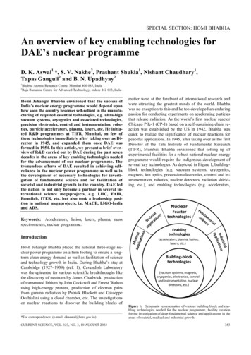
This is an extract from the WHO book "X-ray equipment maintenance andrepairs workbook for radiographers & radiological technologists" by Ian RMcClelland.Copyright: World Health Organization 2004. Reproduced with permissionAPPENDIX EX-ray equipment operationIntroduction to X-ray equipment operationPART I THE P R O D U C T I O N O FX-RAYSAimThe aim is t o provide an overall view of current X-rayequipment design and operation. This information isintended to enhance the maintenance and repairssections of this workbook, by providing a detailedexamination of equipment operation requirements. I naddition, t o provide some of the technical knowledgerequired by an electrician, or electronics technician,assisting in repairing the equipment.ObjectWhen carrying out routine maintenance, and inparticulav, diagnosing incorrect equipment operation,a good knowledge of how equipment operates isrequired.The material in this appendix is intended both as arevision of equipment operation, and to provide specific information of equipment internal operation.Thisincludes operational sequence of events,and the internal tests and checks carried out by the equipment.Thisis also an introduction to X-ray systems for an electrician or electronics technician, who may be asked toassist in the event of a problem.The first three partshave been provided as the background for thisintroduction.1. Production of X-rays2.3.4.5.6.The X-ray tubeHigh voltage generationThe X-ray generator control unitThe high-tension cableX-ray collimator7, X-ray tube suspension8. The grid and Potter Buclg9. Tomography10. The fluoroscopy table11. The automatic film processora.b.c.d.e.f.g.The X-ray tubeBremsstrahlung radiationCharacteristic radiationX-ray propertiesFiltersSpecification of minimum filtrationThe inverse square lawa. The X-ray tubeThe X-ray tube consists of an anode and cathodeinside an evacuated glass envelope. The cathode is afilament, which when made very hot, emits electrons.When a high voltage supply is placed between thecathode and anode, the electrons from the cathodestrilte the anode, releasing X-rays. See Fig E-1. Thereare two main types of X-ray radiation generated:Bremsstrahlung (braking radiation) and characteristicradiation.A t i i g h v o l t a g e ig E-I. The X-ray tubeI?
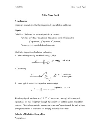
X-RAY EQUIPMENT MAINTENANCE AND REPAIRS WORKBOOK206b. Bremsstrahlung radiotionshell, giving up its energy as an X-ray photon.This hasa predominant energy of 591teV. See Fig E-3.There are other transitions, notably from the 'M'shell t o the 'I(' shell (67.2 keW and 'N' shell to the 'I('shell (69keVI.The above energy levels are specific fortungsten, and are known as 'Characteristic radiation'.Note. To eject an electron from the K shell, theincoming electron requires energy gveater than 70kV,which is the binding energy of the I( shell electron tothe nucleus of a tungsten atom. Below 70lkV, radiationis entirely due t o Bremsstrahlung.At 80 kV, characteristic radiation is about lo%, and a t 150 kV is about28% of the total usable X-ray beam.When an electron passes close to the nucleus of ananode atom, it is deflected, and its speed or energyreduced. At the same time, an X-ray photon is produced, which has an energy level equal to that lost bythe electron. See Fig E-2. Peak X-ray energy, expressedin 'electron-volts' or 'IteV', occurs only when an electron strikes the nucleus, giving up all its energy immediately.The electron will continue to pass through theanode atoms, and produce further X-ray photons.However, about 99.5% of the electron energy is lost ingenerating heat.Fig E-3. Characteristic radiation.-.-d. X-ray properties,X-ray beam quality and quantity depends on threemain factors.Fig E-2. Bremsstrahlung radiation-The IkV applied between anode and cathode-Filtration to remove low energy X-rays.-The amount of electron emission from the cathode,which affects quantity only.-The film focus distance (FFD). Radiation is reducedby the inverse square law.c. Characteristic radiationThis occurs when an incoming electron collides withan electron in the inner'l('shell.To replace the missingelectron, an electron moves from the 'L' shell to the I(Foll i n output i s d u eI25I50X-royI75I100I125I150photon energy. (keV)Fig E-4. illustration of relative kV output, for three values of kV
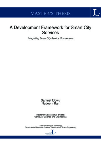
APPENDIX E. X-RAY EQUIPMENT OPERATION207e. FiltersX-ray photons below -40lteV have little penetratingpower in standard diagnostic X-ray procedures, andonly contribute to unwanted radiation of the patient.To remove these lower energy X-rays, added filters areplaced in theX-ray beam.The filter material is normallymade of pure aluminium. For special applicationsfilters made of different materials may be used.Theseare called 'I Edge' filters. An example of this is anX-ray tube used in mammography, which may have amolybdenum filter.Where it is desired to make most use of low lteVradiation, some collimators have a removable filter.Thishas a safety switch, so that if the filter is removed,X-ray generation is not permitted above a specifiedkV level.Table E-I. Minimum half value layer, atdifferent kV levelsX-ray tube voltage(IcV)Minimum permissible firstHALF-VALUE LAYER (mm Al)f: Specification of minimum filtrationMost countries specify a minimum filtration that willbe used for diagnostic X-ray.The total filtration is thecombination of the X-ray tube glass, the mirror in acollimatov, plus the added filter in the X-ray beam.Toensure the minimum required filtration is obtained,tables are provided for measurement purposes.Typical half value layers are provided in tableE-1. The actual specification may differ in somecountries.How to measure the half-value layerAt a specified kV, a radiation meter measures theradiation from the X-ray tube. Added aluminiumfiltration is placed in the beam. The amount ofaluminium to reduce the beam by 50% is called thehalf-value layer.Referring to table E-1, at 100 kV, this should requirea t least 2.7mm of aluminium.I f the specified value of aluminium reduces radiation by more than 50%, total filtration is insufficient, so more permanent aluminium must beplaced in the X-ray beam.g. The inverse square lawThe quantity of X-rays available for a given areadepends on the distance from the X-ray tube. For agiven distance, the X-ray beam may cover an area of10 x 10cm. I f we double the distance the same beamwill now cover an area of 20 x 20cm, in other words,four times the previous area. Howevev, the radiationavailable for each 10 x 10cm section is now only onequarter its previous value. See Fig E-5.LeiWhen the distance fromthe focal spat is doubled,the available radiation i nthe s a m e a r e a is o n equarter its prevous value.Fig E-5. Illustration of the inverse square law
X-RAY EQUIPMENT MAINTENANCE AND REPAIRS WORKBOOK208motor. Special ball bearings are required, designed towithstand the heat from the anode. A stator windingis placed over the anode end of the X-ray tube, to formthe energising section of the motor. See Fig E-7.PART 2 T H E X-RAY TUBEContentsa.b.c.d.e.f.g.h.i.The stationary anode X-ray tubeThe rotating anode X-ray tubeThe X-ray tube housingThe X-ray tube focal spotAnode angleMaximum anode heat inputAnode rotation speedsEffect of rotation speed on outputAnode heat and cooling timej. The X-ray tube filamentk. Filament focusi. Grid controlled X-ray tubec. The X-ray tube housinga. The stationary anode X-ray tubeThis is usually found in portable X-ray generators, or indental units. The anode is a small insert of tungsten,inside a large copper support. The copper is t o helpadsorb the heat produced.As a general rule focal spotsare larger than for the rotating anode type,as the heatproduced is in a very small area.b. The rotating anode X-ray tubeBy rotating the anode, the heat produced is spreadaround a wide area.This allows time for heat to beabsorbed into the body of the anode.As a result, muchsmaller focal spots may be used, together with anincrease in output.Rotation is achieved by attaching a copper cylinderto the anode. This forms the 'rotor' of an inductioniRotating anode X-rayThe housing is lead lined, so that radiation only exitsvia the port in front of the focal spot. This port isusually a truncated plastic cone, extending from thesurface of the housing close t o the X-ray tube glass.This reduces the absorption of X-rays due to the oil.Oil provides the required high voltage insulation, andserves to conduct the heat from the anode and statorwinding t o the outside surface. A bellows is providedt o allow the oil to expand as it becomes h0t.A thermalsafety switch is fitted to ensure protection againstexcessive housing heat. I n some cases, this may be amicro switch, operated when the bellows expandsbeyond its operating limit. See Fig E-9.d. The X-ray tube focal spotBy focussing a vertical beam of electrons, onto theanode, which has a specific angle, an effective smallarea of X-rays results.This is ltnown as the 'focal spot',and the method of generation as the 'iine focusprinciple'.As indicated in Fig E-10, this effective focal spotbecomes enlarged as the useful beam is projectedtowards the cathode end of the X-ray tube. While thespot will become smaller towards the anode side, apoint is reached where X-ray generation rapidlybecomes less. This is ltnown as the 'heel effect'. SeeFig E-11.Gloss bulbtubeFig E-7. Anode and motor for a rotating anode X-ray tubek
APPENDIX E. X-RAY EQUIPMENT OPERATION209T U housing is i filled.iThis p r o v i d e r h i g h voltageinsuiotion, a n d c o n d u c t sh e o i f r o m the X-ray t u b eo n d staiorX-raytube a n d housing.X-ray\/;"tb",k:'tube-windingBellows. Allowswhen h e a t e dT h e r m o safetyh e o i sensor)Anode S u p p o r tCathodeReceptacleLA",,,ReceptacleFig E-9. The X-ray tube and housingX-rayX-raytube anodeWtube cathodendActual focal spotFilament insidefocus cupThe width 'W' depends ont h e f i l a m e n t d i a m e t e r anddesign o f the focal c u p .Change o f effective f o c a l s p o towoy from p e i p e n d i c u l o r t o t h eonodeCathodeAnode1 1Projecied focal spotFig E-10. Formation of the focal spote. Anode angleThe wider the anode angle, the greater will be the filmcoverage at a spec f cdistance. However, to maintainthe same focal spot size, the length 'l'of the electronbeam must be reduced.This results in a smaller areato dissipate the immediate heat, so the maximumoutput of the tube has to be reduced. See Fig E-10.A common angle for an over-table tube is 12? Anunder-table tube in a fluoroscopy table may have anangle of 16g.With a 12F: angle, rad ationmay cover a35 x 35cm film at a FFD of 100cm,while a 16O lngle-100P60 80040 x 20rrO201 6 12 84t Anode48121620CathodeRadiation centreFig E-l I. Relative radiation output for twoanode angles
X-RAY EQUIPMENT MAINTENANCE AND REPAIRS WORKBOOK210would cover the same film a t a distance of 65cm.Fig E-11 indicates the relative radiation output fortwo common anode angles. The rapid fall off to theanode side is due t o heel affect.Table E-2. Common anode speeds.Thespeed shown in brackets is the actualobtained speed, versus the theoreticalmaximum d)5 0 Hz3000(-2850)9000(-8700)fi Maximum anode heat inputThe maximum heat input for the X-ray tube anode isdetermined by:The anode material.Anode rotation speed.Anode diameter.Focal spot size.The kV waveform. (Single-phase, or three-phase)An X-ray tube anode load capacity is rated as thenumber of kilowatts for an exposure time of 0.1second.This is calculated from the rating chart for aspecified mode of operation. For example,In Fig E-lla,the r o d u coft mA and kV a t 0.1 second is 381tW.h. Effect of rotation speed on outputHigh-speed operation is of maximum benefit for shortexposure times. (The generator should also sufficientoutput, to take advantage of high-speed anode rotation.) I n Fig E-12b two load lines are indicated, onefor high-speed, and one for low-speed operation.Whilethis example is for 100Kv operation, a similar result isobtained for other load factors.g. Anode rotation speedsThere are two anode rotation speeds in use, low speedand high speed.These depend on the power main supplyfrequency. High speed was originally obtained fromstatic frequency-triplers, which generate the third harmonic of the mainsfrequency. Later high-speed systemsuse solid-state inverters,so high speed is now usually atthe higher 10800frequency, even with a 50Hz supply.With the simple form of induction motor used torotate the anode, there will always be some slip, so theanode does not reach the full possible speed. Thenominal speed that may be reached is indicated inbracltets in table E-2.i. Anode heat and cooling timeA stationary anode X-ray tube can have the coppersection of the anode extended outside the glasscontainev, and into the oil. This allows direct conduction of anode heat. This is not possible for arotating anode, and heat is dissipated by directradiation from the anode disk. Depending on anodediameter and thickness, this can take a long timetime.A typical cooling chart is provided in Fig E-13, andthe formulas for calculation of the heat unit providedin table E-3.Maximum exposure t i m e (Seconds)Fig E-I2a. A typical anode-rating chart
-APPENDIX E. X-RAY EQUIPMENT OPERATION21 111.: j Fig E-I 2b. High-speed operation allows an increased anode load300070X250mm0 2000*0,51503 z 100x0,rn2 50Q0012345 6 78 9T i m e in minutes101112 13 1 4 1 5Fig E-13. A typical chart to indicate the rise in anode heat versus the cooling timeTable E-3. Formulas used for anode heat-unit calculationkV waveformPer exposureContinuousSingle phase,full wave operation.HU kVxmAxsHUIs IkV x mAThree phase, full wave operation.HU IkV x mA x s x 1.35HUIs kV x mA x 1.35Medium or high frequency inverter.HU kV x mA x s x 1.35HUIs IkV x mA x 1.35j.The X-ray tube filamentTo emit electrons, the filament must be brought to awhite heat temperature.As the temperature increases,a point is reached where, despite further increases intemperature, only a small increase in emission results.I n this area tungsten evaporation also increases,greatly reducing the filament life. This determinesthe maximum usable emission from the filament.Fig EL14 indicates the non-linear characteristic of thefilament.When the kV is increased, electron emission fromthe filament to the anode also increases.This is commonly known as the 'Space charge' effect. As anexample, Fig-14 shows the change of mA that cantake place as kV is increased, In this example, with a
X-RAY EQUIPMENT MAINTENANCE AND REPAIRS WORKBOOK212I.Grid controlled X-ray tube6tLYIX3.54.04.5505.5Filament current (Amps)Fig E-14. A typical filament emission chartfilament current of 5.OA, a t 40kV the emission is160mA, and increases t o 325mA a t 80 kV.To lkeep mAconstant, as kV is changed, the generator controlmust change the filament current.This is called 'spacecharge compensation'.I n this design, the focus cup is brought out t o aseparate connection. By applying a strong negativevoltage between the focus cup and the filament,electron emission is suppressed.With this change of connection, the cathode cup isnow referred t o as a 'grid'. Grid control allows controlof the X-ray exposure, while high voltage is continuously applied between anode and cathode. I n operation, the grid is lkept negative with respect to thefilament, until an exposure is required. During an exposure, the negative voltage is removed, permittingemission from the filament.To terminate the exposurethe grid is again made negative in respect t o thefilament.Grid control may be used where rapid precise exposures are required, such as i n special procedure rooms.However the most common use of grid control is incapacitor discharge mobiles.k. Filament focusTo enable a tight beam of electrons to the anode, thefilament is placed inside a 'focus cup'.The focus cupis connected directly to the common centre point ofthe cathode.Normally the two filaments are placed side by side,and angled,so t o strike the same anode position.Somedesigns instead have the filaments placed end. Thisallows formation of two separate tracks on the anode.These traclts can have separate angles to suit therequired application.There is, however, a problem withtwo separate tracks, as exact alignment of the collimator to both tracks is not possible.Fine a n dbroadfilament f o rcommononode f o c u strackEnd viewkFilamentalignment f o rtwo seperatefocus trackso n the a n o d eFig E-15. Two versions of filament design forthe cathode
APPENDIX E. X-RAY EQUIPMENT OPERATION213PART 3 HIGHVOLTAGEGENERATIONContentsa. Single-phase, self rectifiedb. Single-phase, full-wave rectifiedc. Three-phase generatorsd. Three-phase 'Six Pulse' generatore. Three-phase 'Twelve Pulse' generatorf. The 'Constant potential' generatorg. High-frequency generatorsh. The capacitor discharge (CD) mobilem'InverseThe high-tension winding is 'centre tapped', so thatboth anode and cathode have equal voltage appliedabove ground potential.Single phase self rectified systems are normallyfound in small portable X-ray generators, or may beused in dental units. Efficiency is low, and long exposure times will be required.6. Single-phase, full-wave reaifiedFuii wave rectification results in both half cycies of theac voltage used for X-ray production. There is nodanger of back-fire, as no negative voitage is appliedto the anode. Much higher output is now avaiiabie. Fuiiwave rectification is used on systems ranging fromportable, dental, mobile, and up to heavy duty fixedinstallations. While self rectified generators may havea maximum output of 10-15mA, full wave rectifiedunits have been produced with up to 800mA output. mA Meter-1Voltage betweenanode a n dcathode.Fig E-17. Single-phase self-rectifiedgeneratora. Single-phase, self rectifiedThe X-ray tube can also be considered as a rectifiev, inthat electrons emitted from the cathode filamenttravel to the positive anode. I f the anode is negativein respect to the cathode, no electron flow occurs.However, in case the anode is very hot, electronemission can also occur from the anode, in which caseelectron flow can exist from the anode to the cathode.This is called 'back-fire', and would damage the filament.To prevent this, an external diode and resistor isfitted to the primary of the HT transformer.The effectis to greatly reduce the avaiiabie high voitage on thenegative half cycie.lbis is called 'inverse suppression'.E f f e c t i v e voltage accrassthe X-ray tubeFig E-18. Single-phase full-wave generatorThe high-tension winding is centre tapped, with thecentre position connected t o ground. This ensuresanode and cathode voltages are equally balancedabove ground potential.As the current in the transformer winding is AC, anadditional rectifier is required for the mA meter (normally mounted on the control front panel). Exposuretimes are in multiples of the power main supply frequency. For a 50Hz supply, exposure time calculationis simple. See table E-4.With a 60Hz suppiy, each pulse is 8.3 millisecondswide. So some generators may indicate exposure timesbelow 0.1 second as a number of pulses, rather thana set time.
X-RAY EQUIPMENT MAINTENANCE A N D REPAIRS WORKBOOK214Table E-4. Indication of exposure time for a single-phase, 50 Hz generator50Hz supply1 0 millisecondsfor each 'pulse'0.01 secondexposure 1pulse.c. Three-phase generatorsBy operating with three-phase power supply, severaladvantages occur:The peak power demand per phase is reduced, withthe input power equally shared between all threephases.Rather than pulsed high voltage, the X-ray tube nowhas continuous voltage supplied, so radiation for agiven ItV and mA is considerably greater.This resultsin shorter exposure times for a given setting, whilethe radiation absorbed by the patient is alsoreduced.Shorter exposure times, down to 0.003 seconds, areavailable. Exposure time calculation for 6OHZ ismore accurate.The X-ray tube has higher anode load capacity forshort exposure times, although for long exposuretimes this will be less.Three phase generators have typical outputs of500mA up to -1200mA.d. Three-phase 'Six Pulse' generatorThis system uses an identical style of winding for boththe anode and cathode side. The windings may beconfigured 'star' or 'delta'. The system obtains itsname due to the six joined together pulses that aregenerated each cycle. The 'ripple factor' for six-pulseis -13%.Three p h o s e'Six Pulse' q e n e r a t o r0.05 secondexposure 5 pulses0.2 secondexposure 20 pulsesI n the example shown below, the secondary windings are both delta configuration.The two isolated setsof windings and rectifier systems allow independentvoltage supply to both anode and cathode. By connecting the common centre point to ground, bothanode and cathode are equally balanced aboveground.See Fig E-19.e. Three-phase 'Twelve Pulse'generatorWith the twelve-pulse generator, one winding is configured delta, and the other star. The voltage pealtsbetween these two windings have a 30 degree phaseshift, so that a peak of the rectified output from thedelta winding will coincide with a trough from the starrectified output.This result in twelve joined togetherpulses for each cycle.The overall ripple-factor is considerably improved, t oa possible 3.5%. This improved ripple factor allowshigher effective radiation output for a set ItV, compared to six-pulse generators. With special exposurecontactor systems, exposure times down t o 0.001seconds have been achieved. Conventional exposurecontactors however, have the same exaosure timelimitations of the six-pulse systems.See Fig E-20."Six Pulse" w a v e f o r mAnode I7- 50:ID IICathode--Ic a A o o d e and cathodewaveforms ore i n ohossThe ideal woveform1s more o f f e n iike thisFig E-19. Three-phase, six-pulse generator50kV
Three-phase Twelve-PulsegeneratorTwelve-PulseAPPENDIX E. X-RAY EQUIPMENT OPERATION1215iwaveformAnodeIv- 50Ii- Anode and cathode o v e l o r m sare phose shiftedThe ideol w o v e f o r m1Is more o f t e n like this(Anode a n d cathodecombined)\Fig E-20. Three-phase twelve-pulse generator-f The 'Constant aotential' peneratorWith this generator, there is NO ripple factor, and thevoltage applied t o theX-ray tube is pure DC.To achievethis, the output of a conventional six-pulse generatoris smoothed by high voltage capacitors. The highvoitage is then passed through a pair of high voltagetetrode valves.These serve to control the exposure,andregulate the actual high voitage supplied to the X-raytube.To achieve good regulation, the high voltageobtained from the generator is set about 50kV higherthan actually required. During the exposure, thetetrodes control the voltage a t the required level tothe X-ray tube. Constant-voltage generators wereused for special procedure rooms,and CTscanners.Theconstruction and maintenance of these systems isexpensive. They have been largely replaced by highfrequency inverter systems. However, they are still inuse for providing a very accurate X-ray calibrationstandard.g. High-frequency generatorsThese are sometimes ltnown as 'medium frequency'generators, depending on the maximum frequency ofthe inverter.Generally, if maximum frequency is below -20 kHz,the generator is called 'medium frequency'. Currenthigh-frequency generators can operate up to 100 kHz,although most systems will operate below 50 kHz.Inside the high-frequency generatov, the AC mainspower is rectified, and smoothed by a large valuecapacitor, to become a DC voltage supply.The'inverter'converts the DC voltage baclc into a high-frequency ACvoltage.This in turn is fed into the primaly winding, ofthe high-tension transformer.High-frequency generators have many advantagesover conventional generators, operating a t 50 or 60Hzpower main frequency.The high-tension transformer now uses ferriteinstead of an iron core, with an increase inefficiency.The required inductance of the transformer windingis reduced, resulting in a big drop of copper resistive loss, again improving efficiency.Transformer manufacturing costs are reduced.High-voltage output is tightly regulated, so normalchanges in power main voltages have no affect onthe exposure.The high-voltage waveform is simiiar to between an deai six-pulse to twelve-pulse generator for amedium-frequency system.A high-frequency generator waveform has less ripple, in many cases lessthan 2%. However, final ripple depends on otherdesiqn considerations.High-voltage production is highly consistent, withlittle variation in residual IcV riuule. (Unlilte threephase systems, this can suffer distortion of the ItVwaveform.)Used in a mobile system, the inverter may operatedirectly from storage batteries, or else from largecapacitors charged via the power point. I n boththese cases, ItV waveform remains similar t o largefixed installations.While earlier medium frequency systems had highdeveiopment costs, present high-frequency systems are more cost effective than conventionalgenerators.
X-RAY EQUIPMENT MAINTENANCE AND REPAIRS WORKBOOK2163 phaseSCR "Bridge"inverterCapacitorsprov de /.,.-.-- -- --LPower 'ON'Contactor'L o n i o c t o ro p e r a t e safter capacitorsare f u l l y c h a r g e dmAWTo k"9''-ControlFig E-Zla. Diagram to illustrate the principle of a high-frequency generatorOn initial power up, a resistor limits the chargingcurrent of the capacitors. This is necessaty, asothetwise with the capacitors discharged; it wouldbe equivalent to placing a short circuit on theoutput of the rectifiers.After the capacitors are charged, another contactor shorts out the resistors.The system is now readyfor operation.The energy stored in the capacitors supplies thehigh peak current required by the inverter.The inverter illustrated is an SCR 'bridge' inverter.The output of this inverter is coupled via a resonantcircuit t o the primary of the HT transformeu,The capacitor 'C', and the inductance 'L', togetherwith the inductance of the transformer windingform a series resonant tuned circuit. The resonantcircuit has two functions.-As the pulse rate of the inverter increases towardsresonance, the energy each pulse produces in theHT transformer secondary also increases. Thisallows avery wide range of control.'High Frequency' generator. i c a lwith t w o t r a n s f o r m e r sand 'voltage-doubler' rectification.-The resonant circuit has a 'flywheel affect', sothat on the reverse half cycle,the back EMF attempts to reverse the current in the pair of SCRsthat produced the initial pulse.This causes thatpair to switch off. (The other pair will produce thenext pulse, but this time in the opposite direction)The high-tension transformer is operated similar toa single-phase generator, with two exceptions.-For medium-frequency generators, added capacitors to provide waveform smoothing. For manyhigh-frequency generators howeveu, the inherentcapacitance of the HT cables provides therequired smoothing, without added capacitors.-A built in resistive voltage divider provides measurement of the high voltage during the exposure.This rneasuvement is compared to a referencevoltage equivalent t o that for the required kV.I f there is any difference, the inverter controlcircuit changes the pulse rate to correct theerror. This is called 'closed loop' or 'feedback'regulation.'High Frequency' generator.Typical arrangement with twot r a n s f o r m e r s , and b r i d g e rectifiers-Fig E-2lb. Two versions of high voltage generation, used with a high-frequency system
APPENDIX E. X-RAY EQUIPMENT OPERATION217h. The capacitor discharpe (CD) mobileThe capacitor-discharge or'CD'generator obtains highvoltage for an exposure directly from a pair of capacitors. These are charged to the required IkV beforemalting an exposure. As the kV for an exposure isapplied to the X-ray tube prior to an exposure, a 'gridcontrolled' X-ray tube is fitted. A negative voltageapplied between the 'grid', or focus-cup, and the filament. This prevents an exposure until the negativevoltage is removed.Although there is a slow capacitor charging time,the capacitor can rapidly discharge through the X-raytube,with peal mA currents up to 500mA.Actual peakmA depends on the X-ray tube used, not the capacitorsystem. During an exposure, the charge on the capacitor drops by 1kV per mAs.OperationThe high voltage capacitors are charged prior topreparation for an exposure.This may take up t o aminute depending on the kV setting required. Aresistor in series with the transformer primary limitsthe charging current, allowing operation from astandard power point.The CD mobile has two capacitors, connected inseries,with the common point connected to ground.This ensures the high-voltage to anode and cathodeof the X-ray tube is equally balanced above groundpotential. The capacitors are usually each of twomicrofarads capacity, and as they are connected inseries, make up a total value of one microfarad.The transformer secondary and rectifiers are connected to the capacitors to form a'voltage doubler'.On the positive half cycle D l conducts, charging C1.On the negative half cycle, conduction is via D2,charging C2.The charge on C l and C2 add togetherto produce the total kV available for an exposure.See Fig E-22.The resistors R 1 and R2 provide a voltage measurement for the charging circuit, and for the kVmeter.At the start of an exposure, the mAs timer operatesa high voltage relay. This removes the negativevoltage applied between grid and cathode. At endof the exposure, the relay stops operating, andthe negative voltage is once more applied to thegrid.Once the capacitors are charged t o the required ItV,the charge will slowly drop, partly due to the conduction of the ItV measurement resistors,and partlydue t o a small 'dark current' current of the X-raytube. (This term is used to describe conduction witha cold cathode filament.) As a result, when the IkVdrops a small amoun
PART 2 THE X-RAY TUBE . motor. Special ball bearings are required, designed to withstand the heat from the anode. A stator winding is placed over the anode end of the X-ray tube, to form . Contents . the energising section of the motor. See Fig E-7. a. The stationary anode X-ray tube b. The rotating anode X-ray tube c. The X-ray tube housing d.


![[AWS Black Belt Online Seminar] AWS X-Ray](/img/17/20200526-blackbelt-x-ray.jpg)