Transcription
Seventh EditionCHAPTER16VECTOR MECHANICS FOR ENGINEERS:DYNAMICSFerdinand P. BeerE. Russell Johnston, Jr.Plane Motion of Rigid Bodies:Forces and AccelerationsLecture Notes:J. Walt OlerTexas Tech University 2003 The McGraw-Hill Companies, Inc. All rights reserved.SeventhEditionVector Mechanics for Engineers: DynamicsContentsIntroductionEquations of Motion of a Rigid BodyAngular Momentum of a Rigid Bodyin Plane MotionPlane Motion of a Rigid Body:d’Alembert’s PrincipleAxioms of the Mechanics of RigidBodiesProblems Involving the Motion of aRigid BodySample Problem 16.1Sample Problem 16.2 2003 The McGraw-Hill Companies, Inc. All rights reserved.Sample Problem 16.3Sample Problem 16.4Sample Problem 16.5Constrained Plane MotionConstrained Plane Motion:Noncentroidal RotationConstrained Plane Motion:Rolling MotionSample Problem 16.6Sample Problem 16.8Sample Problem 16.9Sample Problem 16.1016 - 21
SeventhEditionVector Mechanics for Engineers: DynamicsIntroduction In this chapter and in Chapters 17 and 18, we will beconcerned with the kinetics of rigid bodies, i.e., relationsbetween the forces acting on a rigid body, the shape and massof the body, and the motion produced. Results of this chapter will be restricted to:- plane motion of rigid bodies, and- rigid bodies consisting of plane slabs or bodies whichare symmetrical with respect to the reference plane. Our approach will be to consider rigid bodies as made oflarge numbers of particles and to use the results of Chapter14 for the motion of systems of particles. Specifically,rrrrF maandM H& GG D’Alembert’s principle is applied to prove that the externalrforces acting on a rigid body are equivalent a vector maattached to the mass center and a couple of moment I α . 2003 The McGraw-Hill Companies, Inc. All rights reserved.16 - 3SeventhEditionVector Mechanics for Engineers: DynamicsEquations of Motion for a Rigid Body Consider a rigid body acted uponby several external forces. Assume that the body is made ofa large number of particles. For the motion of the mass centerG of the body with respect to theNewtonian frame Oxyz,rr F ma For the motion of the body withrespect to the centroidal frameGx’y’z’,rr M G H& G System of external forces isequipollent to therr systemconsisting of ma and H& G . 2003 The McGraw-Hill Companies, Inc. All rights reserved.16 - 42
SeventhEditionVector Mechanics for Engineers: DynamicsAngular Momentum of a Rigid Body in Plane Motion Angular momentum of the slab may becomputed byn r rrH G (ri′ vi′ mi )i 1n rr r [ri′ (ω ri′) mi ]i 1(r ω ri′ 2 mir Iω) After differentiation,rrrH& G I ω& I α Consider a rigid slab inplane motion. Results are also valid for plane motion of bodieswhich are symmetrical with respect to thereference plane. Results are not valid for asymmetrical bodies orthree-dimensional motion. 2003 The McGraw-Hill Companies, Inc. All rights reserved.16 - 5SeventhEditionVector Mechanics for Engineers: DynamicsPlane Motion of a Rigid Body: D’Alembert’s Principle Motion of a rigid body in plane motion iscompletely defined by the resultant and momentresultant about G of the external forces. Fx ma x Fy ma y M G Iα The external forces and the collective effectiveforces of the slab particles are equipollent (reduceto the same resultant and moment resultant) andequivalent (have the same effect on the body). d’Alembert’s Principle: The external forcesacting on a rigid body are equivalent to theeffective forces of the various particles formingthe body. The most general motion of a rigid body that issymmetrical with respect to the reference planecan be replaced by the sum of a translation and acentroidal rotation. 2003 The McGraw-Hill Companies, Inc. All rights reserved.16 - 63
SeventhEditionVector Mechanics for Engineers: DynamicsAxioms of the Mechanics of Rigid Bodiesrr The forces F and F ′ act at different points ona rigid body but but have the same magnitude,direction, and line of action. The forces produce the same moment aboutany point and are therefore, equipollentexternal forces. This proves the principle of transmissibilitywhereas it was previously stated as an axiom. 2003 The McGraw-Hill Companies, Inc. All rights reserved.16 - 7SeventhEditionVector Mechanics for Engineers: DynamicsProblems Involving the Motion of a Rigid Body The fundamental relation between the forcesacting on a rigid body in plane motion andthe acceleration of its mass center and theangular acceleration of the body is illustratedin a free-body-diagram equation. The techniques for solving problems ofstatic equilibrium may be applied to solveproblems of plane motion by utilizing- d’Alembert’s principle, or- principle of dynamic equilibrium These techniques may also be applied toproblems involving plane motion ofconnected rigid bodies by drawing a freebody-diagram equation for each body andsolving the corresponding equations ofmotion simultaneously. 2003 The McGraw-Hill Companies, Inc. All rights reserved.16 - 84
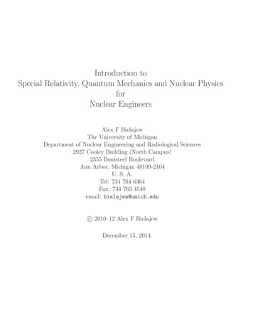
SeventhEditionVector Mechanics for Engineers: DynamicsSample Problem 16.1SOLUTION: Calculate the acceleration during theskidding stop by assuming uniformacceleration. Draw the free-body-diagram equationexpressing the equivalence of theexternal and effective forces.At a forward speed of 30 ft/s, the truck Apply the three corresponding scalarbrakes were applied, causing the wheelsequations to solve for the unknownto stop rotating. It was observed that thenormal wheel forces at the front and reartruck to skidded to a stop in 20 ft.and the coefficient of friction betweenthe wheels and road surface.Determine the magnitude of the normalreaction and the friction force at eachwheel as the truck skidded to a stop. 2003 The McGraw-Hill Companies, Inc. All rights reserved.16 - 9SeventhEditionVector Mechanics for Engineers: DynamicsSample Problem 16.1SOLUTION: Calculate the acceleration during the skidding stopby assuming uniform acceleration.v 2 v02 2a ( x x0 )v0 30fts2x 20 ft ft 0 30 2a (20 ft ) s a 22.5fts Draw a free-body-diagram equation expressing theequivalence of the external and effective forces. Apply the corresponding scalar equations. Fy (Fy )eff Fx (Fx )effN A NB W 0 FA FB ma µk (N A N B ) µ kW (W g )aµk 2003 The McGraw-Hill Companies, Inc. All rights reserved.a 22.5 0.699g 32.216 - 105
SeventhEditionVector Mechanics for Engineers: DynamicsSample Problem 16.1 Apply the corresponding scalar equations. M A (M A )eff (5 ft )W (12 ft )N B (4 ft )ma1 W W a 5W 4 a 5 4 12 g 12 g N B 0.650WNB N A W N B 0.350WN rear 12 N A 12 (0.350W )N rear 0.175WFrear µ k N rear (0.690)(0.175W )N front 12 NV 12 (0.650W )Frear 0.122WN front 0.325WF front µ k N front (0.690 )(0.325W )F front 0.0.227W 2003 The McGraw-Hill Companies, Inc. All rights reserved.16 - 11SeventhEditionVector Mechanics for Engineers: DynamicsSample Problem 16.2SOLUTION: Note that after the wire is cut, allparticles of the plate move along parallelcircular paths of radius 150 mm. Theplate is in curvilinear translation. Draw the free-body-diagram equationexpressing the equivalence of theexternal and effective forces.The thin plate of mass 8 kg is held inplace as shown.Neglecting the mass of the links,determine immediately after the wirehas been cut (a) the acceleration of theplate, and (b) the force in each link. Resolve into scalar component equationsparallel and perpendicular to the path ofthe mass center. Solve the component equations and themoment equation for the unknownacceleration and link forces. 2003 The McGraw-Hill Companies, Inc. All rights reserved.16 - 126
SeventhEditionVector Mechanics for Engineers: DynamicsSample Problem 16.2SOLUTION: Note that after the wire is cut, all particles of theplate move along parallel circular paths of radius150 mm. The plate is in curvilinear translation. Draw the free-body-diagram equation expressingthe equivalence of the external and effectiveforces. Resolve the diagram equation into componentsparallel and perpendicular to the path of the masscenter. Ft (Ft )effW cos 30 mamg cos 30 ()a 9.81m/s 2 cos 30 a 8.50 m s 2 2003 The McGraw-Hill Companies, Inc. All rights reserved.60o16 - 13SeventhEditionVector Mechanics for Engineers: DynamicsSample Problem 16.2 Solve the component equations and the momentequation for the unknown acceleration and linkforces. M G ( M G )eff(FAE sin 30 )(250 mm) (FAE cos 30 )(100 mm)(FDF sin 30 )(250 mm ) (FDF cos 30 )(100 mm) 038.4 FAE 211.6 FDF 0FDF 0.1815 FAE Fn (Fn )effa 8.50 m s260oFAE FDF W sin 30 0FAE 0.1815 FAE W sin 30 0(FAE 0.619(8 kg ) 9.81m s 2FDF 0.1815 (47.9 N ) 2003 The McGraw-Hill Companies, Inc. All rights reserved.)FAE 47.9 N TFDF 8.70 N C16 - 147
SeventhEditionVector Mechanics for Engineers: DynamicsSample Problem 16.3SOLUTION: Determine the direction of rotation byevaluating the net moment on thepulley due to the two blocks. Relate the acceleration of the blocks tothe angular acceleration of the pulley. Draw the free-body-diagram equationexpressing the equivalence of theexternal and effective forces on thecomplete pulley plus blocks system.A pulley weighing 12 lb and having aradius of gyration of 8 in. is connected to Solve the corresponding momenttwo blocks as shown.equation for the pulley angularAssuming no axle friction, determine theacceleration.angular acceleration of the pulley and theacceleration of each block. 2003 The McGraw-Hill Companies, Inc. All rights reserved.16 - 15SeventhEditionVector Mechanics for Engineers: DynamicsSample Problem 16.3SOLUTION: Determine the direction of rotation by evaluating the netmoment on the pulley due to the two blocks. M G (10 lb)(6 in ) (5 lb)(10 in ) 10 in lbrotation is counterclockwise.note:I mk 2 W 2kg12 lb 8 ft 32.2 ft s 2 12 2 0.1656 lb ft s 2 Relate the acceleration of the blocks to the angularacceleration of the pulley.a A rAα (10ft )α12 2003 The McGraw-Hill Companies, Inc. All rights reserved.aB rBα6 ) (12ft α16 - 168
SeventhEditionVector Mechanics for Engineers: DynamicsSample Problem 16.3 Draw the free-body-diagram equation expressing theequivalence of the external and effective forces on thecomplete pulley and blocks system. Solve the corresponding moment equation for the pulleyangular acceleration. M G (M G )eff6 )(10 lb)(126 ft ) (5 lb )(10ft ) I α mB aB (12ft m Aa A (10ft )12126101066510(10)(12 ) (5)(12 ) (0.1656)α (32.2 )(12 α )(12 ) (32.2 )(12 )(10)12α 2.374 rad s 2I 0.1656 lb ft saA ()ft s6aB (12 α )ft s 210 α122Then,2a A rAα()a A 1.978 ft s 2()aB 1.187 ft s 2 (10ft ) 2.374 rad s 212aB rBα6 (12ft ) 2.374 rad s 2 2003 The McGraw-Hill Companies, Inc. All rights reserved.16 - 17SeventhEditionVector Mechanics for Engineers: DynamicsSample Problem 16.4SOLUTION: Draw the free-body-diagram equationexpressing the equivalence of the externaland effective forces on the disk.A cord is wrapped around ahomogeneous disk of mass 15 kg.The cord is pulled upwards with aforce T 180 N. Solve the three corresponding scalarequilibrium equations for the horizontal,vertical, and angular accelerations of thedisk. Determine the acceleration of the cord byevaluating the tangential acceleration ofthe point A on the disk.Determine: (a) the acceleration of thecenter of the disk, (b) the angularacceleration of the disk, and (c) theacceleration of the cord. 2003 The McGraw-Hill Companies, Inc. All rights reserved.16 - 189
SeventhEditionVector Mechanics for Engineers: DynamicsSample Problem 16.4SOLUTION: Draw the free-body-diagram equation expressing theequivalence of the external and effective forces on thedisk. Solve the three scalar equilibrium equations. Fx (Fx )effax 00 ma x Fy (Fy )effT W ma yay (T W 180 N - (15 kg ) 9.81m s 2 m15 kga y 2.19 m s 2 M G (M G )eff Tr I α α )(12 mr 2 )α2T2(180 N ) (15 kg )(0.5 m )mrα 48.0 rad s 2 2003 The McGraw-Hill Companies, Inc. All rights reserved.16 - 19SeventhEditionVector Mechanics for Engineers: DynamicsSample Problem 16.4 Determine the acceleration of the cord by evaluating thetangential acceleration of the point A on the disk.racord (a A )t a (a A G )t( 2.19 m s 2 (0.5 m ) 48 rad s 2)acord 26.2 m s 2ax 0a y 2.19 m s 2α 48.0 rad s 2 2003 The McGraw-Hill Companies, Inc. All rights reserved.16 - 2010
SeventhEditionVector Mechanics for Engineers: DynamicsSample Problem 16.5SOLUTION: Draw the free-body-diagram equationexpressing the equivalence of theexternal and effective forces on thesphere.A uniform sphere of mass m and radiusr is projected along a rough horizontalsurface with a linear velocity v0. Thecoefficient of kinetic friction betweenthe sphere and the surface is µk.Determine: (a) the time t1 at which thesphere will start rolling without sliding,and (b) the linear and angular velocitiesof the sphere at time t1. Solve the three corresponding scalarequilibrium equations for the normalreaction from the surface and the linearand angular accelerations of the sphere. Apply the kinematic relations foruniformly accelerated motion todetermine the time at which thetangential velocity of the sphere at thesurface is zero, i.e., when the spherestops sliding. 2003 The McGraw-Hill Companies, Inc. All rights reserved.16 - 21SeventhEditionVector Mechanics for Engineers: DynamicsSample Problem 16.5SOLUTION: Draw the free-body-diagram equation expressing theequivalence of external and effective forces on thesphere. Solve the three scalar equilibrium equations. Fy (Fy )effN W 0F x (Fx )eff F ma µ k mg N W mga µk g M G (M G )effFr I α5 µk g2 rNOTE: As long as the sphere both rotates and slides,its linear and angular motions are uniformlyaccelerated.(µ k mg )r (23 mr 2 )α 2003 The McGraw-Hill Companies, Inc. All rights reserved.α 16 - 2211
SeventhEditionVector Mechanics for Engineers: DynamicsSample Problem 16.5 Apply the kinematic relations for uniformly acceleratedmotion to determine the time at which the tangential velocityof the sphere at the surface is zero, i.e., when the spherestops sliding.v v 0 a t v 0 ( µ k g )t5 µk g t 2 r ω ω 0 αt 0 a µk g5 µk gα 2 rAt the instant t1 when the sphere stops sliding,v1 rω1 5 µk g v0 µ k gt1 r t1 2 r 5 µk g 5 µ k g 2 v0 t1 2 r 2 r 7 µ k g t1 2 v07 µk gω1 ω1 5v v1 rω1 r 0 7 r v1 75 v0 2003 The McGraw-Hill Companies, Inc. All rights reserved.5 v07 r16 - 23SeventhEditionVector Mechanics for Engineers: DynamicsConstrained Plane Motion Most engineering applications involve rigidbodies which are moving under givenconstraints, e.g., cranks, connecting rods, andnon-slipping wheels. Constrained plane motion: motions withdefinite relations between the components ofacceleration of the mass center and the angularacceleration of the body. Solution of a problem involving constrainedplane motion begins with a kinematic analysis. e.g., given θ, ω, and α, find P, NA, and NB.- kinematic analysis yields a x and a y .- application of d’Alembert’s principle yieldsP, NA, and NB. 2003 The McGraw-Hill Companies, Inc. All rights reserved.16 - 2412
SeventhEditionVector Mechanics for Engineers: DynamicsConstrained Motion: Noncentroidal Rotation Noncentroidal rotation: motion of a body isconstrained to rotate about a fixed axis that doesnot pass through its mass center. Kinematic relation between the motion of the masscenter G and the motion of the body about G,at r αan r ω 2 The kinematic relations are used to eliminateat and an from equations derived fromd’Alembert’s principle or from the method ofdynamic equilibrium. 2003 The McGraw-Hill Companies, Inc. All rights reserved.16 - 25SeventhEditionVector Mechanics for Engineers: DynamicsConstrained Plane Motion: Rolling Motion For a balanced disk constrained toroll without sliding,x rθ a r α Rolling, no sliding:F µs Na rαRolling, sliding impending:F µs Na rαRotating and sliding:F µk Na , rα independent For the geometric center of anunbalanced disk,a O rαThe acceleration of the mass center,rrraG aO aG Orrr aO aG O aG O( 2003 The McGraw-Hill Companies, Inc. All rights reserved.)t ()n16 - 2613
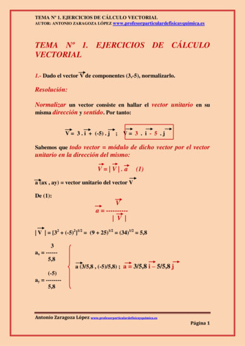
SeventhEditionVector Mechanics for Engineers: DynamicsSample Problem 16.6SOLUTION: Draw the free-body-equation for AOB,expressing the equivalence of theexternal and effective forces.mE 4 kg Evaluate the external forces due to theweights of gear E and arm OB and theeffective forces associated with theangular velocity and acceleration.k E 85 mmmOB 3 kgThe portion AOB of the mechanism isactuated by gear D and at the instantshown has a clockwise angular velocityof 8 rad/s and a counterclockwiseangular acceleration of 40 rad/s2. Solve the three scalar equationsderived from the free-body-equationfor the tangential force at A and thehorizontal and vertical components ofreaction at shaft O.Determine: a) tangential force exertedby gear D, and b) components of thereaction at shaft O. 2003 The McGraw-Hill Companies, Inc. All rights reserved.16 - 27SeventhEditionVector Mechanics for Engineers: DynamicsSample Problem 16.6SOLUTION: Draw the free-body-equation for AOB. Evaluate the external forces due to the weights ofgear E and arm OB and the effective forces.()WE (4 kg ) 9.81m s 2 39.2 N()WOB (3 kg ) 9.81m s 29.4 N2(I Eα mE k E2α (4kg )(0.085 m )2 40 rad s 2) 1.156 N m(mE 4 kgk E 85 mmmOB 3 kgα 40 rad sω 8 rad/s2mOB (aOB )t mOB (r α ) (3 kg )(0.200 m ) 40 rad s 2) 24.0 N( )mOB (aOB )n mOB r ω 2 (3 kg )(0.200 m )(8 rad s )2 38.4 NI OBα (121 mOB L2 )α 121 (3kg )(0.400 m)2 (40 rad s2 ) 1.600 N m 2003 The McGraw-Hill Companies, Inc. All rights reserved.16 - 2814
SeventhEditionVector Mechanics for Engineers: DynamicsSample Problem 16.6 Solve the three scalar equations derived from the freebody-equation for the tangential force at A and thehorizontal and vertical components of reaction at O. M O ( M O )effF (0.120m ) I Eα mOB (aOB )t (0.200m ) I OBα 1.156 N m (24.0 N )(0.200m ) 1.600 N mF 63.0 N Fx ( Fx )effWE 39.2 NWOB 29.4 NI Eα 1.156 N mRx mOB (aOB )t 24.0 NRx 24.0 N Fy ( Fy )effmOB (aOB )t 24.0 NR y F WE WOB mOB (aOB )mOB (aOB )n 38.4 NR y 63.0 N 39.2 N 29.4 N 38.4 NR y 24.0 NI OBα 1.600 N m 2003 The McGraw-Hill Companies, Inc. All rights reserved.16 - 29SeventhEditionVector Mechanics for Engineers: DynamicsSample Problem 16.8SOLUTION: Draw the free-body-equation for thesphere, expressing the equivalence of theexternal and effective forces. With the linear and angular accelerationsrelated, solve the three scalar equationsderived from the free-body-equation forthe angular acceleration and the normalA sphere of weight W is released withand tangential reactions at C.no initial velocity and rolls without Calculate the friction coefficient requiredslipping on the incline.for the indicated tangential reaction at C.Determine: a) the minimum value of Calculate the velocity after 10 ft ofthe coefficient of friction, b) theuniformly accelerated motion.velocity of G after the sphere hasrolled 10 ft and c) the velocity of G if Assuming no friction, calculate the linearacceleration down the incline and thethe sphere were to move 10 ft down acorresponding velocity after 10 ft.frictionless incline. 2003 The McGraw-Hill Companies, Inc. All rights reserved.16 - 3015
SeventhEditionVector Mechanics for Engineers: DynamicsSample Problem 16.8SOLUTION: Draw the free-body-equation for the sphere, expressingthe equivalence of the external and effective forces. With the linear and angular accelerations related, solvethe three scalar equations derived from the free-bodyequation for the angular acceleration and the normaland tangential reactions at C. M C (M C )eff(W sin θ )r (ma )r Iα (mrα )r (52 mr 2 )αa rα W 2W 2 rα r r α g 5 g a rα (α 5 g sin θ7r5 g sin 30 7)5 32.2 ft s 2 sin 30 7a 11.50 ft s 2 2003 The McGraw-Hill Companies, Inc. All rights reserved.16 - 31SeventhEditionVector Mechanics for Engineers: DynamicsSample Problem 16.8 Solve the three scalar equations derived from the freebody-equation for the angular acceleration and thenormal and tangential reactions at C. Fx (Fx )eff W sin θ F maW 5 g sin θ g72F W sin 30 0.143W7N W cosθ 0 Fy (Fy )eff5 g sin θα 7ra rα 11.50 ft s 2N W cos 30 0.866W Calculate the friction coefficient required for theindicated tangential reaction at C.F µs Nµs F 0.143W N 0.866W 2003 The McGraw-Hill Companies, Inc. All rights reserved.µ s 0.16516 - 3216
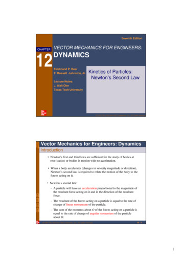
SeventhEditionVector Mechanics for Engineers: DynamicsSample Problem 16.8 Calculate the velocity after 10 ft of uniformlyaccelerated motion.v 2 v02 2a ( x x0 )() 0 2 11.50 ft s 2 (10 ft )rv 15.17 ft s Assuming no friction, calculate the linear accelerationand the corresponding velocity after 10 ft.α 5 g sin θ7r M G (M G )eff0 Iα Fx (Fx )eff W W sin θ ma a g (α 0)a 32.2 ft s 2 sin 30 16.1ft s 2a rα 11.50 ft s 2v 2 v02 2a ( x x0 )() 0 2 16.1ft s 2 (10 ft ) 2003 The McGraw-Hill Companies, Inc. All rights reserved.rv 17.94 ft s16 - 33SeventhEditionVector Mechanics for Engineers: DynamicsSample Problem 16.9SOLUTION: Draw the free-body-equation for thewheel, expressing the equivalence of theexternal and effective forces.A cord is wrapped around the innerhub of a wheel and pulledhorizontally with a force of 200 N.The wheel has a mass of 50 kg and aradius of gyration of 70 mm.Knowing µs 0.20 and µk 0.15,determine the acceleration of G andthe angular acceleration of the wheel. Assuming rolling without slipping andtherefore, related linear and angularaccelerations, solve the scalar equationsfor the acceleration and the normal andtangential reactions at the ground. Compare the required tangential reactionto the maximum possible friction force. If slipping occurs, calculate the kineticfriction force and then solve the scalarequations for the linear and angularaccelerations. 2003 The McGraw-Hill Companies, Inc. All rights reserved.16 - 3417
SeventhEditionVector Mechanics for Engineers: DynamicsSample Problem 16.9SOLUTION: Draw the free-body-equation for the wheel,. Assuming rolling without slipping, solve the scalarequations for the acceleration and ground reactions. M C (M C )eff(200 N )(0.040 m ) ma (0.100 m ) Iα8.0 N m (50 kg )(0.100 m )2α (0.245 kg m 2 )αα 10.74 rad s 2I mk 2 (50 kg )(0.70 m )2()a (0.100 m ) 10.74 rad s 2 1.074 m s 2 0.245 kg m 2 Fx (Fx )effAssume rolling without slipping,a rα (0.100 m )α(F 200 N ma (50 kg ) 1.074 m s 2F 146.3 N) Fx (Fx )effN W 0()N mg (50kg ) 1.074 m s 2 490.5 N 2003 The McGraw-Hill Companies, Inc. All rights reserved.16 - 35SeventhEditionVector Mechanics for Engineers: DynamicsSample Problem 16.9 Compare the required tangential reaction to themaximum possible friction force.Fmax µ s N 0.20(490.5 N ) 98.1 NF Fmax , rolling without slipping is impossible.Without slipping,F 146.3 N N 490.5 N Calculate the friction force with slipping and solve thescalar equations for linear and angular accelerations.F Fk µ k N 0.15(490.5 N ) 73.6 N Fx (Fx )eff200 N 73.6 N (50 kg )aa 2.53 m s 2 M G (M G )eff(73.6 N )(0.100 m ) (200 N )(0.0.060 m )() 0.245 kg m 2 αα 18.94 rad s 2003 The McGraw-Hill Companies, Inc. All rights reserved.2α 18.94 rad s 216 - 3618
SeventhEditionVector Mechanics for Engineers: DynamicsSample Problem 16.10SOLUTION: Based on the kinematics of the constrainedmotion, express the accelerations of A, B,and G in terms of the angular acceleration.The extremities of a 4-ft rodweighing 50 lb can move freely andwith no friction along two straighttracks. The rod is released with novelocity from the position shown. Draw the free-body-equation for the rod,expressing the equivalence of theexternal and effective forces. Solve the three corresponding scalarequations for the angular acceleration andthe reactions at A and B.Determine: a) the angularacceleration of the rod, and b) thereactions at A and B. 2003 The McGraw-Hill Companies, Inc. All rights reserved.16 - 37SeventhEditionVector Mechanics for Engineers: DynamicsSample Problem 16.10SOLUTION: Based on the kinematics of the constrained motion,express the accelerations of A, B, and G in terms ofthe angular acceleration.Express the acceleration of B asrrra B a A aB AWith aB A 4α , the corresponding vector triangle andthe law of signs yieldsa A 5.46αaB 4.90αThe acceleration of G is now obtained fromr rrra a G a A aG A where aG A 2αResolving into x and y components,a x 5.46α 2α cos 60 4.46αa y 2α sin 60 1.732α 2003 The McGraw-Hill Companies, Inc. All rights reserved.16 - 3819
SeventhEditionVector Mechanics for Engineers: DynamicsSample Problem 16.10 Draw the free-body-equation for the rod, expressingthe equivalence of the external and effective forces. Solve the three corresponding scalar equations for theangular acceleration and the reactions at A and B. M E (M E )eff(50)(1.732) (6.93α )(4.46) (2.69α )(1.732) 2.07αα 2.30 rad s 250 lb1 ml 2 1(4 ft )2I 1212 32.2 ft s 2 2.07 lb ft s 2I α 2.07α50(4.46α ) 6.93αma x 32.250ma y (1.732α ) 2.69α32.2α 2.30 rad s 2 Fx (Fx )effRB sin 45 (6.93)(2.30 )RB 22.5 lb Fy (Fy )effrRB 22.5 lb45oRA (22.5) cos 45 50 (2.69 )(2.30 ) 2003 The McGraw-Hill Companies, Inc. All rights reserved.RA 27.9 lb16 - 3920
Seventh Vector Mechanics for Engineers: Dynamics Edition 16 - 4 Equations of Motion for a Rigid Body Consider a rigid body acted upon by several external forces. Assume that the body is made of a large number of particles. For the motion of the mass center G of the body with respect to the Newtonian frame Oxyz, F ma r r