Transcription
1INSTRUCTION MANUALBINTEL TELESCOPESDOBSONIAN TELESCOPESTHE BINOCULAR AND TELESCOPE SHOP84 Wentworth Park RdGlebeNSW2037519 Burke RdCamberwell VIC3124Email: info@bintel.com.auWWW: www.bintelshop.com.au & www.bintel.com.au
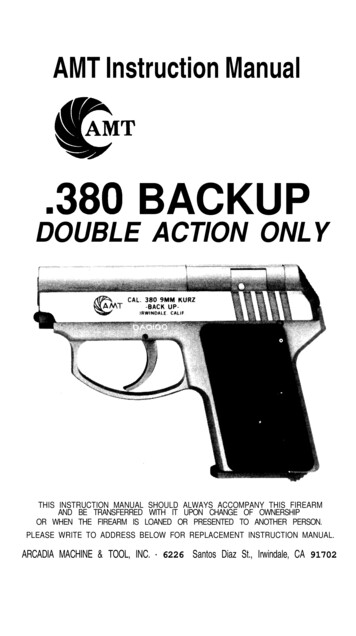
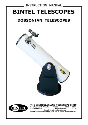
2Parts of a Bintel DobsonianCrayford Focuserwith 10:1 MicrofocusFinderscopeFinder BracketsAlignment ScrewsSpring Loaded Self Adjuster2” - 1.25” AdapterFocuser KnobOptical Tube AssemblyAltitude BearingWith Braking SystemPrimaryMirror CellLeft Side PanelCarry HandleCooling FanTop BaseplateEyepiece RackGround BoardBintel LabelYour Guarantee of QualityCongratulations and thank you for selecting a quality Bintel telescope. Your new Bintel Dobsonian is designedfor high-resolution viewing of astronomical objects. With its precision optics and Dobsonian mount, you’ll beable to locate and enjoy thousands of fascinating celestial denizens, including the planets, Moon, and a varietyof deep-sky galaxies, nebulas, and star clusters. If you have never owned a telescope before, we would like towelcome you to amateur astronomy. Take some time to familiarize yourself with the night sky. Learn torecognize the patterns of stars in the major constellations. With a little practice, a little patience, and areasonably dark sky away from city lights, you’ll find your telescope to be a never-ending source of wonder,exploration, and relaxation.For after sales service or friendly advice contact Bintels Service Dept.Our qualified technical and astronomy staff will be happy to help.These instructions will help you set up, properly use and care for your telescope.Please read them over thoroughly before getting started.
3Table of Contents1. Overview . .22. Unpacking and Parts List . .33. Base Assembly. . . . 43. Using Your Telescope . . .64. Collimation (Aligning the Mirrors) . . 95. Astronomical Observing . . . 116. Care and Maintenance . . .157. Specifications (BT 202 and BT 252) . . 158. Specifications (BT 302) . . . .169. Suggested Accessories . . .1610. Warranty . . . .162. UnpackingThe telescope will arrive in two boxes.The larger box contains the optical tube assembly and accessories.The Large flat pack contains the unassembled Dobsonian base and hardware.Below is a packing slip for both boxes.When unpacking the boxes please be careful as there are some small parts that could easily become lost.We suggest that this be done indoors. We recommend keeping the original shipping containers. In the eventthat the telescope needs to be shipped to another location, or returned to Bintel for warranty repair, havingthe proper shipping containers will help ensure that your telescope will survive the journey intact.Make sure all the parts in the Parts List below are present. Be sure to check boxes carefully, as some partsare small.If anything appears to be missing or broken, call Bintel Customer Support (02) 9518 7255 for assistance.Parts ListBox #2: Dobsonian BaseBox #1: Optical Tube Assembly and tical tube assemblyDust cover26mm Bintel Wide Angle eyepiece 2” barrel(all models)15mm Bintel Plossl eyepiece 1.25” barreldiameter (all models)9mm Bintel Plössl eyepiece, 1.25" barreldiameter (all models)Right Angled 8 x 50 finder scopeFinder scope bracket with O-RingMoon FilterInstruction ManualAltitude Bearings with Braking SystemHardware Pack121218WARNING:Never look directly at the Sun throughyour telescope or its finder scope—evenforaninstant—withoutaprofessionally made solar filter thatcompletely covers the front of theinstrument, or permanent eye damagecould result. Young children shoulduse this telescope only with adultsupervision.DescriptionLeft panelRight panelFront braceTop baseplate (has countersunk holes in it)Ground baseplateMetal disksRoller Bearing MatAluminium Tube (sleeve between top andbottom baseplates)121331Eyepiece rackEyepiece rack mounting wood screws(length 3/4")HandleSocket-head cap screws, 5/16" (black)Large Allen wrench (6mm)Base assembly screws (length 2")(BT 202 / BT252)Base assembly screws (length 2") (BT 302)Small Allen wrench (size 4mm)Plastic feetFeet attachment wood screws (length 1")Large hex-head bolt (length 3")
42. AssemblyOnce all base hex head screws are in place tightenthem with Allen Wrench.Now that you have unpacked the boxes andfamiliarized your-self with all the parts in front ofyou, it’s time to begin assembly.Start with the Base.Assembly of the Dobsonian baseThe base need only be assembled once, unless youdisassemble it for long-term storage. The assemblyprocess takes about 15 minutes and requires,anadjustable crescent wrench, and the providedAllen wrenches.1. LooselyLooselyattachfrontboardtotwothe sidetwoattachthe thefrontboardto thesidewithbasefourassemblyof the baseassemblypanelswithpanelsfour of thescrews(I) inscrews inthe Usepredrilledholes.Use tothetightenAllenthe predrilledholes.the Allenwrenchwrench Doto tightenthe screws.Dothenotscrewscomthe screws.not completelytightenyet. pletely tighten the screws yet. (See image below) Note: Be sure that the Predrilled holesfor therack are on the LEFT of the(See imageat eyepieceright)rocker box. (as view from the rear).The Threaded inserts on the Front Brace areon the inside.2. Turn this assembly upside down, and screw onthe top of the base board. Continue using the large ,hex-head screws . (See image Below)3. Screw the 3 feet into the small pre drilled holeson the bottom of the ground board with a Phillipshead screw driverGroundboard with Metal disks andRoller Bearing fitted4. With the rocker box still upside down, Place theRoller Bearing Mat between the two metal disks.Put the aluminium spacer tube into the bottom ofthe rocker box and put the metal disks and bearingmat over the spacer tube. Now put the Groundboard on with the spacer tube coming through it.The captive T-Nut should be on the top (at this time)The 3 rubber feet should be on the top.Now using Pivot Bolt screw it through the aluminiumspacer tube from inside the rocker box and tighten.There is a fixed T-screw in the bottom of the groundboard to secure it all.Note: The Pivot Bolt has a Roller Bearing in itDo Not over tighten. LARGE Washer on bottom.Small Washerbetween Roller Bearing andPlastic Knob.
55. One side panel has 2 small pre-drilled holes formounting the Eyepiece Rack. Attach the EyepieceRack with its screws. (see image below)Optical Tube AssemblyWe are now ready to assemble the tube section ofthe telescope. First unpack the parts required andset aside.1. Take Tube Assembly out of box and standupright with sitting on the ground.2.The Side Bearing Kit must be installed.This comes in two brown boxes insideAccessories Box. (see image at right)the6. Attach thehandles to the Front Brace with the socket-headscrews. Insert the screws through the handle andinto the predrilled holes. Fit the nuts at the rear ofthe front panel. Tighten the bolts with an Allenwrench. Note: Be sure that the threadedinsertsare on the inside of the rocker box.Attach the handle to the front panel with the twoblack socket-head screws. Insert the screws throughthe handle and into the predrilled holes.Fit the nuts at the rear of the front panel. Tightenthe bolts with an Allen wrench. (see image below)Altitudewith builting Sys-Bearing-in Breaktem3.With the telescope standing in the uprightposition. The side bearing housing is visible and itcontains both a Scale and Two (2) Small Brass Nutswith Phillips Head Screws protruding from them.\FrontHandleYourRockerBoxshouldnow be complete and look like the image below.AltitudeHousingNutsBearingwith Brass4.Remove Phillips Head Screws and place Altitude Bearing in position so that the screws will screw into the BrassNuts.AltitudeFittedBearing
6Installing the Finder Scope3. Using Your TelescopeThe Bintel Dobsonians come with a high quality,Right Angled 8x50 achromatic finder scope.This greatly aids in finding objects to view in thenight sky. The “8” means it magnifies 8 times, the“50” means it has a 50mm diameter lens. It showsaround 5 degrees of sky. Before attaching the finderscope bracket to the telescope tube, it is convenientto first install the finder in the bracket. Thread thetwo finder scope alignment thumb screws (withknurled lock nuts attached) into the holes on theoutside of the finder bracket’s rings. Pull the springloaded adjuster out to enable you to slide the finderscope through the bracket’s rings and secure it inplace with the alignment thumb screws; make surethe knurled lock nuts are adequately loosened to dothis. The finder scope should be oriented within thefinder bracket as shown in Figure 6. Now, connectthe entire assembly to the telescope. Do this by firstremoving the round knurled nuts on the two threaded bolts adjacent to the focuser. Then position theholes in the base of the finder bracket over the bolts,and secure the bracket in place with the two roundnuts. The large (objective) end of the finder scopeshould bepointing toward the front (open) end ofthe telescope tube.It is best to get a feel for the basic functions of theBintel Dobsonian during the day, before observingastronomical objects at night. This way you will nothave to fumble around trying to orient yourself inthe dark! Find a spot outdoors where you have plenty of room to move around the telescope, and whereyou have a clear view of some object or vista that isat least 1/4-mile away. It is not critical that the basebe exactly level, but it should be placed on somewhat flat ground or pavement to ensure smoothmovement of the telescope. Remember, never pointthe telescope at or near the Sun without using aproper solar filter over the front aperture!Altitude and AzimuthThe base of the Bintel Dobsonian permits motion ofthe telescope along two axes: altitude (up/down)and azimuth (left/right) (see Figure 8). This is veryconvenient, since up/down and left/right are themost “natural” ways that people aim. As a result,pointing the telescope is exceptionally easy.Simply take hold of the telescope tube and move itleft or right so the base rotates about its centralazimuth bolt, and move it up or down so the altitudeside bearings rotate in the base’s cradle.Both motions can be made simultaneously and in acontinuous manner for easy aiming. Move thetelescope gently - let it glide. In this way you canpoint the telescope to any position in the night sky,from horizon to horizon. When moving he telescope,it may be convenient to grasp the front end of thetelescope tube so that your fingers just protrude intoit; this provides a convenient “handle”.Right Angled 8x50 finder scope and bracket.Inserting an EyepieceThe final step in the assembly process is to insert aneye-piece into the telescope’s focuser. Take the cover cap off the end of the focuser drawtube. Loosenthe thumb screw on the 1.25" eyepiece adapter. Donot loosen the two thumb screws on the 2" eyepieceadapter. Insert one of the supplied eyepieces, thensecure it by retightening thethumbscrew on the1.25" eyepiece adapter. The other eyepiece can beplaced in the eyepiece rack until it is needed. Theassembly of your Bintel Dobsonian is now complete. It should appear as shown on page 2. Thedust cap on the front of the telescope tube shouldalways remain in place when the telescope is not inuse. It is also a good idea to store eyepieces in aneyepiece case and to replace the cover caps on thefocuser and finder scope when the telescope is idle.The Bintel Dobsonian has two axis of motion:Altitude (up/down) and Azimuth (left/right)Eyepiece being fitted to telescope
7Viewing with EyeglassesFocusing the FinderScopeIf you wear eyeglasses, you may be able to keepthem on while you observe, if your eyepieces haveenough eye relief to allow you to see the whole fieldof view. You can try this by looking through theeyepiece first with your glasses on and then withthem off, and see if the glasses restrict the view toonly a portion of the full field. If they do, you caneasily observe with your glasses off by justrefocusing the telescope the needed amount.If you suffer from severe astigmatism, however, youmay find images noticeably sharper with your glasses on point you want to look at. Then look throughthe telescope’s eyepiece to see if that point is centered in the field of view. If it is, the job is done. Ifnot, make the necessary adjustmentsIf, when looking through the finderscope, the imagesappear somewhat out of focus, you will need torefocus the finderscope for your eyes. Loosen thelock ring located behind the objective lens cell on thebody of the finderscope Back the lock ring off by afew turns, for now. Refocus the finderscope on adistant object by threading the objective lens cell inor out on the finderscope body. Precise focusing willbe achieved by focusing the finderscope on a brightstar. Once the image appears sharp, retighten thelock ring behind the objective lens cell. The finderscope’s focus should not need to be adjusted again.Aligning the FinderscopeThe finder scope must be aligned accurately with thetelescope for proper use. To align it, first aim themain telescope in the general direction of an objectat least 1/4-mile away -the top of a telephone pole,a chimney, etc. Position that object in the center ofthe telescope’s eyepiece.Now, look in the finderscope. Is the object visible?Ideally, it will be somewhere in the field of view. If itis not, some coarse adjustments of the twofinderscope alignment thumb screws will be neededto get the finderscope roughly parallel to the maintube. With the image in the finderscope’s field ofview, you will now use the alignment thumb screwsto center the object on the intersection of thecrosshairs.Aiming/Pointing the TelescopeWith the finder scope aligned, the telescope can bequickly and accurately pointed at anything you wishto observe. The finderscope has a much wider fieldof view than the telescope’s eyepiece, and thereforeit is much easier to first center an object in the finder scope. Then, if the finderscope is accuratelyaligned, the object will also be centered in thetelescope’s field of view.Start by once again moving the telescope until it ispointed in the general direction of the object youwant to see. Some observers find it convenient tosight along the tube to do this. Now, look in thefinderscope. If your general aim is accurate, theobject should appear somewhere in the field of view.Make small adjustments to the telescope’s positionuntil the object is centered on the finder’s crosshairs.Now, look in the telescope’s eyepiece and enjoy theview!Focusing the TelescopeBy loosening one alignment thumb screw andtightening another you change the line of sight ofthe finderscope. Continue making adjustments to thevarious alignment thumb screws until the image inboth the finder scope and the telescope’s eyepiece isexactly centered. Check the alignment by movingthe telescope to another object and fixing thefinderscope’s crosshairs on the exact point you wantto look at.Then look through the telescope’s eyepiece to see ifthat point is centered in the field of view. If it is, thejob is done. If not, make the necessary adjustmentsuntil the two images match up. The finderscopealignment needs to be checked before everyobserving session. This can easily be done at night,before viewing through the telescope. Choose anybright star or planet, center the object in the telescope eyepiece, and then adjust the finderscope’salignment thumb screws until the star or planet isalso centered on the finder’s crosshairs.Insert the low power 26mm eyepiece into thefocuser and secure it with the thumb screw . Movethe telescope so the front (open) end is pointing inthe general direction of an object at least 250maway. Now, with your fingers, slowly rotate one ofthe focusing knobs until the object comes into sharpfocus. Go a little bit beyond sharp focus until theimage just starts to blur again, then reverse therotation of the knob, just to make sure you’ve hit theexact focus point.If you have trouble focusing, rotate the focusingknob so the drawtube is in as far as it will go. Nowlook through the eyepiece while slowly rotating thefocusing knob in the opposite direction. You shouldsoon see the point at which focus is reached.On the underside of the focuser there are two metalthumbscrews. The thumbscrew closest to the bodyof the scope will lock the focuser position, the otherthumbscrew will adjust focuser tension.The finderscope is an invaluable tool for locatingobjects in the night sky; its usage for this purposewill be discussed later., in detail.Focusing the telescope
8MagnificationNow that the object you want to view is wellcentered in the 25mm eyepiece, you may want toincrease the magnification to get a closer view.Loosen the thumb screw on the 1.25" eyepieceadapter and remove the eyepiece. Place it in theeyepiece rack, if you wish. Insert the 9mm eyepieceinto the 1.25" eyepiece adapter, then retighten thethumb screw. If you were careful not to bump thetelescope, the object should still be centered withinthe field of view. Notice that the object being viewedis now larger, but somewhat dimmer.The Bintel Dobsonians are designed to accept anyeyepiece with a barrel diameter of 1.25" or 2".Magnification, or power, is determined by the focallength of the telescope and the focal length of theeyepiece. Therefore, by using eyepieces of differentfocal lengths, the resultant magnification can bevaried.Magnification is calculated as follows:Magnification Telescope Focal Length (mm)Eyepiece Focal Length (mm)The Bintel BT 202 Dobsonian has a focal length of1200mm. So, the magnification with the supplied26mm eyepiece is 1200mm 26mm 46x.The Bintel BT 252 Dobsonian has a focal length of1250mm. So, the magnification with the supplied32mm eye-piece is 1250mm 32mm 39x.The Bintel BT 302 Dobsonian has a focal length of1500mm. So, the magnification with the supplied32mm eye-piece is 1500mm 32mm 46.8x.The maximum attainable magnification for atelescope is directly related to how much light itsoptics can collect.A telescope with more lightcollecting area, oraperture, can yield highermagnifications than a smaller aperture telescope.The maximum practical magnification for anytelescope, regardless of optical design, is about 40xper inch of aperture. This translates to about 320xfor the Bintel BT 202 and 400x for the Bintel BT 252and 480x for the Bintel BT 302Keep in mind that as magnification is increased, thebrightness of the object being viewed will decrease;this is an inherent principle of the physics of opticsand cannot be avoided. If magnification is doubled,animageappearsfourtimesdimmer.If magnification is tripled, image brightness isreduced by a factor of nine!Note About High Magnifications:Maximum magnifications are achieved only underthe most ideal viewing conditions at the bestobserving sites. Most of the time, magnifications arelimited to 200x or less, regardless of aperture. Thisis because the Earth’s atmosphere distorts light as itpasses through. On nights of good “seeing”, theatmosphere will be still and will yield the leastamount of distortion. On nights of poor seeing, theatmosphere will be turbulent, which means differentdensities of air are rapidly mixing. This causessignificant distortion of the incoming light, whichprevents sharp views at high magnifications.Carrying the TelescopeMoving the Bintel Dobsonian is easy to do. Removeany eye-pieces from the telescope and eyepiecerack, and place them in an eyepiece case. You canalso remove the finder scope and finder scope bracket, if you wish.To carry the base, simply grasp the handle on thefront of it. The tube should be carried with twohands. One way to do this is to grasp the tube withone hand while grasping the mirror cell end with theother . Another way is to grasp the tube with bothhands around its circumference. Be careful whensetting the tube down on its end so as not to bend ordamage the primary mirror collimation screws on thebottom of the primary mirror cell.When putting the Bintel Dobsonian into a vehicle,common sense prevails. It is especially importantthat the optical tube does not knock around; this cancause the optics to become misaligned, and coulddent the tube.
94. Collimation(Aligning The Mirrors)Collimation is the process of adjusting the mirrors sothey are perfectly aligned with one another.Your telescope’s optics were aligned in our workshops, and should not need much adjustment unlessthe telescope was handled roughly during shipment.Accurate alignment is important to ensure the peakperformance of your telescope, so it should bechecked regularly. Collimation is relatively easy todo and can be done in daylight. To check thecollimation, remove the eyepiece and look down thefocuser drawtube. You should see the secondarymirror centered in the drawtube as well as thereflection of the primary mirror centered in thesecondary mirror, and the reflection of thesecondary mirror (and your eye) centered in thereflection of the primary mirror, as in Figure 12a.If anything is off-center, as in Figure 12b, proceedwith the following collimation procedure It helps toput a piece of white paper on the inside of theoptical tube opposite the focuser. It forms a brightbackground behind the secondary mirror, making iteasier to distinguish the mirror holder from thebackground.Use a Collimating ToolTo aid in centering your line of sight down thefocuser drawtube, and in centering the mirrorreflections during collimation, it is very helpful to usea precision collimating tool containing crosshairs,such as the Orion Collimating Eyepiece (#3640).We strongly recommend that you purchase one.Alternatively, you can make a crude collimating toolout of an empty, black plastic 35mm film canister.It will not have crosshairs, so it won’t be as precise,but it will be better than nothing. Cut 1/2" from thetop lip of the canister and put a 1/16" to 1/8"diameter hole in the center of its bottom. The filmcanister collimating tool goes into the focuser like aneyepiece, with the bottom end out.The Bintel Deluxe Laser Collimator can also be used.It comes with it’s own instruction manual.Aligning the Secondary MirrorWith eyepiece removed, look straight down theopen focuser drawtube at the secondary (diagonal)mirror. Ignore the reflections for the time being.The secondary mirror itself should be centered in thefocuser drawtube, in the direction parallel to thelength of the telescope. If it isn’t, as in Figure 14b,it must be adjusted. (It helps to adjust thesecondary mirror in a brightly lit room with thetelescope pointed toward a bright surface, such aswhite paper or a wall.) Loosen the three smallalignment screws in the center hub of the secondarymirror holder several turns. Now hold the secondarymirror holder stationary (be careful not to touch thesurface of the secondary mirror!), while turning thecenter Phillips head screw (as in Figure 13).Turning the bolt clockwise will move the secondarymirror toward the front opening of the optical tube,while turning the bolt counter-clockwise will movethe secondary mirror toward the primary mirror.When the secondary mirror is centered in the focuserdraw-tube, rotate the secondary mirror holder slightly until the reflection of the primary mirror is as centered in the secondary mirror as it will get. It stillmay not be perfectly centered, but that is OK.Now tighten the three alignment screws to securethe secondary mirror in that position. Thisadjustment will rarely need to be done, if ever.Figure 12a When all optical elements are collimatedthe view through the focuser should look like this.Figure 12bAll elementsare out of alignmentFigure 12cSecondary iscentered under focuser butneeds adjustment.Figure 12dSecondary iscollimatedbutprimaryneeds adjustmentFigure 13 Adjust the tilt of the secondary mirror by adjustingthe three alignment screws with a Phillips head screwdriver
10Adjusting the Primary MirrorThe final adjustment is made to the primary mirror.It will need adjustment if, as in Figure 12d, thesecondary mirror is centered under the focuser andthe reflection of the primary mirror is centered in thesecondary mirror, but the small reflection of thesecondary mirror (with your eye inside) is off-center.The tilt of the primary mirror is adjusted with threespring-loaded collimation thumb screws on the backend of the optical tube (bottom of the primary mirrorcell); these are the larger thumb screws. The otherthree smaller thumb screws lock the primary mirror’sposition in place; these thumb screws must beloosened before any collimation adjustments can bemade to the primary mirror.To start, unthread the thumb screws that lock theprimary mirror in place a few turns each (Figure 14).The thumb screws are slotted, so if they are toodifficult to loosen with your fingers, use a flat-headscrewdriver.Now, try tightening or loosening one of the springloaded collimation thumb screws one turn. Look intothe focuser and see if the secondary mirror reflectionhas moved closer to the center of the primary mirrorreflection. Repeat this process on the other twocollimation thumb screws, if necessary. It will take alittle trial and error to get a feel for how to tilt themirror in this way to center the reflection. (It helpsto have two people for primary mirror collimation,one to look in the focuser while the other adjusts thecollimation thumbscrews.) Do not loosen (i.e., rotatecounter-clockwise) each collimation thumb screw toomuch, or the thumb screw will completely unthreadfrom the mirror cell. Rather, try tightening the othertwo collimation thumb screws. Once the secondarymirror reflection is centered in the primary mirrorreflection, retighten the thumb screws that lock theprimary mirror’s position in place.The view through the focuser should now show thereflection of the primary mirror is centered in thesecondary mirror, and the reflection of thesecondary mirror is centered in the reflection of theprimary mirror. A simple star test will tell you whether the optics are accurately collimated.Shows the collimation adjustment screwsStar-Testing the TelescopeWhen it is dark, point the telescope at a bright starand accurately center it in the eyepiece’s field-ofview. Slowly defocus the image with the focusingknob. If the telescope is correctly collimated, theexpanding disk should be a perfect circle (Figure16). If the image is unsymmetrical, the scope is outof collimation. The dark shadow cast by thesecondary mirror should appear in the very center ofthe out-of-focus circle, like the hole in a doughnut.If the “hole” appears off-center, the telescope is outof collimation.If you try the star test and the bright star you haveselected is not accurately centered in the eyepiece,then the optics will always appear out of collimation,even though they may be perfectly aligned. It is critical to keep the star centered, so over time you willneed to make slight corrections to thetelescope’s position in order to account for the sky’s apparent motion.Shows Star images when testing collimationShows the Primary Mirror locking screws
115. Astronomical ObservingObserving TipsA. Site SelectionPick a location away from street lights and brightyard lighting. Avoid viewing over rooftops andchimneys, as they often have warm air currentsrising from them, which distort the image seen inthe eyepiece. Similarly, you should not observethrough an open window from indoors. Better yet,choose a site out-of-town, away from any “lightpollution”. You’ll be stunned at how many more starsyou’ll see! Most importantly, make sure that anychosen site has a clear view of a large portion of thesky.B. Seeing and TransparencyAtmospheric conditions play a huge part in quality ofviewing. In conditions of good “seeing”, startwinkling is minimal and objects appear steady inthe eyepiece. Seeing is best overhead, worst at thehorizon. Also, seeing generally gets better aftermidnight, when much of the heat absorbed by theEarth during the day has radiated off into space.Typically, seeing conditions will be better at sitesthat have an altitude over about 3000 feet. Altitudehelps because it decreases the amount of distortioncausing atmosphere you are looking through.A good way to judge if the seeing is good or not is tolook at bright stars about 40 above the horizon.If the stars appear to “twinkle”, the atmosphere issignificantly distorting the incoming light, and viewsat high magnifications will not appear sharp. If thestars appear steady and do not twinkle, tions will be possible. Also, seeingconditions are typically poor during the day. This isbecause the heat from the Sun warms the air andcauses turbulence. Good “transparency” is especiallyimportant for observing faint objects. It simplymeans the air is free of moisture, smoke, and dust.All tend to scatter light, which reduces an object’sbrightness.C. Cooling the TelescopeAll optical instruments need time to reach “thermalequilibrium” to achieve maximum stability of thelenses and mirrors, which is essential for peakperformance. When moved from a warm indoorlocation, outside to cooler air (or vice-versa),a telescope needs time to cool to the ambienttemperature.All Bintel Dobsonian models have a Cooling Fan toassist in thecoolingdown period prior to use.Caution: Cooling fanshould be turned offbefore the scope isused. The battery packnormally sits in thebottom of the rocker.D. Let Your Eyes Dark-AdaptDo not expect to go from a lighted house into thedarkness of
Congratulations and thank you for selecting a quality Bintel telescope. Your new Bintel Dobsonian is designed for high-resolution viewing of astronomical objects. With its precision optics and Dobsonian mount, you'll be able to locate and enjoy thousands of fascinating celestial denizens, including the planets, Moon, and a variety