Transcription
INSTRUCTION MANUALOrionSkyQuest XT10Dobsonian Reflector #9990Customer Support (800) 676-1343E-mail: support@telescope.comCorporate Offices (831) 763-7000Providing Exceptional Consumer Optical Products Since 1975P.O. Box 1815, Santa Cruz, CA 95061
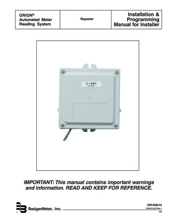
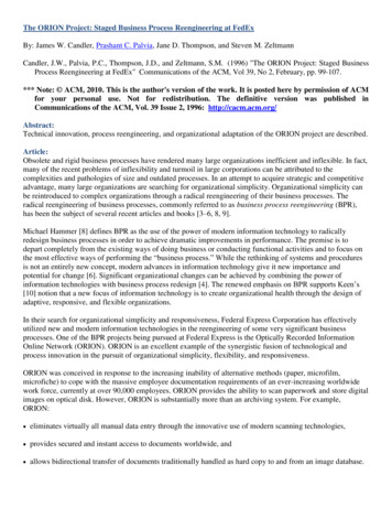
Secondary mirror holder with3-vane spider (not visible)Finder scopeFinder scope bracketEyepieceFocus knobOptical tubeAltitude side bearingCorrecTension (XT)Friction Optimization systemRight side panelPull loopFront braceEyepiece rackHandlePrimarymirror cellLeft side panelTop baseplateGround baseplateFoot (3)Figure 1. The SkyQuest XT10 parts diagram.Welcome to an exciting new world of adventure! Your SkyQuest XT10 Dobsonian is a high-quality optical instrument designed to bring you dazzling views of the outer reaches of our universe. With specialnew innovations, such as the CorrecTension (XT) Friction Optimization system, large format focuser, anddeluxe accessory package, this telescope represents a giant leap forward in the evolution of theDobsonian. Whether you are brand-new to amateur astronomy or a seasoned stargazer, the SkyQuestXT10 Dobsonian will provide many evenings of enjoyment and fascination.2
Table of Contents1. Unpacking. 32. Assembly . 43. Using Your Telescope . 74. Collimation (Aligning the Mirrors) . 105. Astronomical Observing . 126. Care and Maintenance . 157. Specifications. 161. Unpacking1Moon filter1Eyepiece rack2Eyepiece rack mounting wood screws (length 3/4")2Spring coils2Pull loops4Nylon spacers (black)21/4" washers (black)2Phillips-head screws (black, length 1-3/4")2Screws with round knobs attached1Handle2Socket head cap screws, 5/16" (black)25/16" washers (black)25/16" nuts (black)WARNING: Never look directly at the1Large Allen wrench (6mm)Sun through your telescope or its finderscope—even for an instant—withouta professionally made solar filter thatcompletely covers the front of theinstrument, or permanent eye damagecould result. Young children should use thistelescope only with adult supervision.Box #2: Dobsonian BaseThe telescope will arrive in two boxes, one containing theoptical tube assembly and accessories, the other containingthe unassembled Dobsonian base. Be careful unpacking theboxes. We recommend keeping the original shipping containers. In the event that the telescope needs to be shipped toanother location, or returned to Orion for warranty repair, having the proper shipping containers will help ensure that yourtelescope will survive the journey intact.Make sure all the parts in the Parts List below are present. Besure to check boxes carefully, as some parts are small. If anything appears to be missing or broken, immediately call OrionCustomer Support (800-676-1343) for assistance.Qty.Description1Left panel1Right panel1Front brace1Top baseplate1Ground baseplate12Base assembly screws (length 2")1Small Allen wrench (size 4mm)Box #1: Optical Tube Assembly and AccessoriesQty. Description3Plastic feet3Feet attachment wood screws (length 1")1Optical tube assembly1Self-adhesive rubber bumper1Dust cover1Large hex-head bolt (length 3")125mm Plössl eyepiece, 1.25" barrel diameter23/8" washers19mm Plössl eyepiece, 1.25" barrel diameter13/8" lock nut18x50 finder scope1Nylon spacer (white)1Finder scope bracket1T-nut6Finder scope alignmentknurled lock nutsParts Listthumbscrewswith3
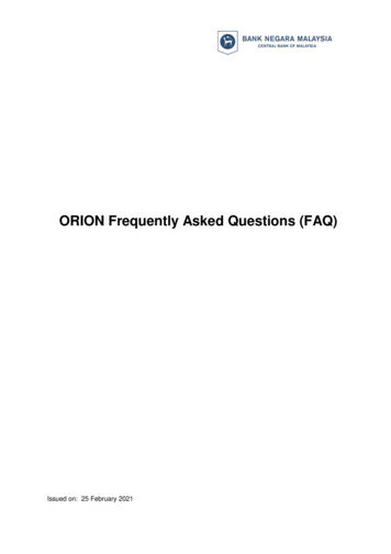
2. Assemblythe top baseplate (D) with the remaining six base assembly screws in the predrilled holes. Tighten all six screws.Now that you have unpacked the boxes and familiarized yourself with all the parts in front of you, it’s time to beginassembly. The optics of the telescope are already installed inthe tube, so most of the required assembly concerns theDobsonian base.4. Tighten the six side screws installed earlier.Assembly of the Dobsonian baseRefer to Figure 2 during base assembly. The base need only beassembled once, unless you disassemble it for long-term storage.The assembly process takes about 30 minutes and requiresa Phillips screwdriver, an adjustable crescent wrench, and theprovided Allen wrenches. When tightening screws, tighten themuntil firm, but be careful not to strip the holes by over-tightening.If you use an electric screwdriver, do final tightening with a standard screwdriver to avoid stripping.6. Insert the T-nut (K) into the center hole of the ground baseplate (A) so the nut’s flanged top is on the same side of thebaseplate as the Teflon pads. Thread the large hex-headbolt (G) with a 3/8" washer (F) attached up through theground baseplate and through the T-nut until it is tight. Nowposition the top baseplate (D) (with side panels attached)over the ground baseplate and lower it so the bolt goesthrough the nylon spacer in the center hole of the top baseplate. Now thread the remaining 3/8" washer (H) and locknut (I) onto the bolt’s shaft.You might need to hold the bolt’shead in place with another crescent wrench or pliers.Tighten the lock nut with the wrench just enough to allow aslight separation of the top and bottom baseplates when themount is lifted. The purpose of the lock nut is merely to keepthe two baseplates from coming apart when moving the telescope. Overtightening the lock nut (I) will make the mountdifficult to rotate in the azimuthal (horizontal) direction.CCBLIHJEDKA5. Insert the white nylon bushing (E) into the hole in the center of the top baseplate (D). Tap the nylon bushing in so itgoes all the way into the top baseplate. The nylon bushingshould be flush with the top surface of the top baseplate.7. Attach the handle (J) to the front brace (B) with the twoblack socket-head screws. Insert the screws through thehandle and into the predrilled holes. Place the 5/16" washers and 5/16" nuts on the protruding ends of the screws.Tighten the nuts with a crescent wrench while holding thescrews stationary with the large Allen wrench.8. The rubber bumper (L) provides a convenient “stop” for thetelescope’s altitude motion; it prevents the telescope mirrorcell from being knocked against the hard surface of thebase’s front brace. At the bottom of the interior surface of thefront brace, you will notice a small index mark engraved.Remove the backing from the rubber bumper and positionthe bumper over the index mark, as shown in Figure 3. Pressfirmly so the adhesive holds the bumper securely in place.FGFigure 2. Exploded view of the Dobsonian base.1. Screw the plastic feet into the underside of the groundbaseplate (A) using the self-tapping wood screws provided,with a Phillips screwdriver. Insert the screws through thefeet and thread them into the predrilled starter holes.2. Loosely attach the front brace (B) to the two side panels (C)with six of the base assembly screws in the predrilled holes.Use the smaller Allen wrench to tighten the screws. Theside panels should be oriented so the SkyQuest labels arefacing outward. Do not completely tighten the screws yet.3. Attach the two sides (C) with the front brace attached to4Figure 3. Position the rubber bumper “stop” over the index mark onthe inside surface of the front brace.
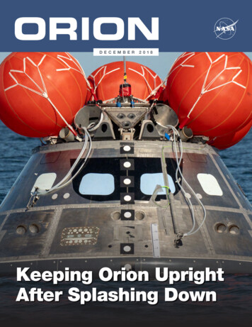
Installing the Eyepiece RackThe aluminum eyepiece rack is a standard accessory onSkyQuest XT10 Dobsonians. It holds four 1.25" eyepieces in aconvenient place on the base, within easy reach while you’reobserving. A 1.25" barlow lens also can be held in the rack.About halfway down the left side panel of the base you willnotice two predrilled starter holes, about 6" apart. Take theblack wood screws that come packaged with the rack, insertthem through the small holes in the rack, and then threadthem into the starter holes with a Phillips screwdriver untiltight (but do not overtighten!). Orient the rack as in Figure 4.Figure 5. Set the optical tube on the “cradle” of the base so that thealtitude side bearings on the tube rest on the white plastic “pads.”Figure 4. Using the two supplied screws, install the aluminumeyepiece rack in the predrilled holes about halfway down the leftside panel of the base.Placing the Optical Tube on the Dobsonian BaseLift the optical tube and set the altitude bearings on eitherside of the tube in the “cradle” of the base (Figure 5). Theunique flange design of the altitude bearing allows for automatic left-to-right centering of the optical tube in the cradle.Once in the cradle, the tube should pivot freely up and downwith gentle hand pressure. Note that the tube will not yet beproperly balanced, since the eyepiece and finder scope arenot in place, and the CorrecTension system has not beeninstalled.Installing the CorrecTension (XT) FrictionOptimization SystemPerhaps the most exciting new feature of the SkyQuest XT10Dobsonian is the CorrecTension Friction Optimization system. Because of their relatively light weight, 10" and smallerDobsonians have always been plagued by insufficient frictionon the altitude bearing surfaces. As a result, such telescopesmove up and down much too freely. This causes problemswhen the observer tries to accurately center and track anobject for viewing, especially at higher powers. Also, the telescope becomes very sensitive to balance, requiring additionalequipment such as counterweight systems or adjustable sidebearings to compensate.SkyQuest XT10 Dobsonians employ a simple yet effectiveremedy for the friction problem that obviates the need forsuch cumbersome countermeasures. CorrecTension FrictionOptimization utilizes a spring coil to “pull” the tube assemblydown onto the altitude bearing pads, thereby increasing thefriction by just the right amount. With CorrecTension, you canchange eyepieces or add a barlow lens without having totediously adjust the telescope’s balance as you would withother Dobsonians. The altitude friction will roughly equal theazimuth friction, ensuring optimal performance.To install the CorrecTension assembly, follow these stepswhile referring to Figure 6:1. Put one of the black nylon spacers on a black Phillipshead screw. The spacer should be oriented so the narrowend seats against the head of the screw. Slip one of theAltitude side bearingBolt w/round knobBlack nylonspacersSpringPhillips headscrew (black)Pull loop1/4" washer(black)Figure 6. Close-up view of the CorrecTension system.5
black 1/4" washers over the end of the screw. Now, threadthe screw into the hole in the base side panel just belowthe cradle. The screw will thread into the preinstalledinsert in the hole. Use a Phillips screwdriver to tighten thescrew. Repeat this procedure on the opposite side panel.2. Next, insert one of the screws with round plastic knobattached through the end ring of one of the springs. Slip ablack nylon spacer onto the screw. Orient the spacer sothe narrow end is closest to the knob. Thread the entireassembly into the hole in the center of the telescope’s altitude side bearing until tight. The end ring of the springshould seat onto the narrow end of the spacer. Repeat thisprocedure for the other altitude side bearing.3. Attach a pull loop to the free end of each spring. Slidethe loop through the opening in the ring on the end ofthe spring.4. Now, pull each spring down using the pull loop, and position the spring’s end ring over the head of the Phillipsscrew (installed in step 1) and onto the narrow part of thenylon spacer, as shown in Figure 7. You needn’t attachboth springs simultaneously; one at a time is fine.The CorrecTension system is now installed and engaged. Ifyou wish to remove the telescope from the base, you will firstneed to disconnect the springs from the “posts” on theDobsonian base. The springs will remain captive on the altitude side bearings, so they will not get lost.Installing the Finder ScopeSkyQuest XT10 Dobsonians come with a high quality, largeaperture 8x50 achromatic crosshair finder scope and a precision metal finder scope bracket as standard equipment. Thisgreatly aids in finding objects to view in the night sky, whichwill be discussed in detail later.Before attaching the finder scope bracket to the telescopetube, it is convenient to first install the finder in the bracket.Thread the six finder scope alignment thumb screws (withknurled lock nuts attached) into the holes on the outside ofthe finder bracket’s rings. Slide the finder scope through thebracket’s rings and secure it in place with the alignmentthumb screws; make sure the knurled lock nuts are adequately loosened to do this. The finder scope should beoriented within the finder bracket as shown in Figure 8.Alignment thumb screwKnurled lock nuta.Lock ringRoundknurled nutFigure 8: The 8x50 finder scope and bracket.Now, connect the entire assembly to the telescope. Do this byfirst removing the round knurled nuts on the two threadedbolts adjacent to the focuser. Then position the holes in thebase of the finder bracket over the bolts, and secure thebracket in place with the two round nuts. The large (objective)end of the finder scope should be pointing toward the front(open) end of the telescope tube.b.Figure 7: (a) To attach the spring to the base, grip the pullloop with your index finger and pull down on the spring. (b)While pulling down, slip the end ring of the spring over thescrew head and onto the narrow part of the nylon spacer,then release the pull loop.6Inserting an EyepieceThe final step in the assembly process is to insert an eyepiece into the telescope’s focuser. Take the cover cap off theend of the focuser drawtube. Loosen the thumb screw on the1.25" eyepiece adapter (see Figure 9). Do not loosen the twothumb screws on the 2" eyepiece adapter. Insert one of thesupplied eyepieces, then secure it by retightening the thumbscrew on the 1.25" eyepiece adapter. The other eyepiece canbe placed in the eyepiece rack until it is needed.
Focuslockthumbscrew1.25" eyepiece adapterWhen moving the telescope, it may be convenient to graspthe front end of the telescope tube so that your fingers justprotrude into it; this provides a convenient “handle”.2"eyepieceadapterFocusknobFigure 9: The large format focuser with eyepiece adaptersattached. The focuser will accept eyepieces with barreldiameters of both 1.25" and 2".AltitudeThe assembly of your SkyQuest Dobsonian is now complete.It should appear as shown in Figure 1. The dust cap on thefront of the telescope tube should always remain in placewhen the telescope is not in use. It is also a good idea to storeeyepieces in an eyepiece case and to replace the cover capson the focuser and finder scope when the telescope is idle.Azimuth3. Using Your TelescopeIt is best to get a feel for the basic functions of theSkyQuest XT10 Dobsonian during the day, before observing astronomical objects at night. This way you will nothave to fumble around trying to orient yourself in the dark!Find a spot outdoors where you have plenty of room tomove around the telescope, and where you have a clearview of some object or vista that is at least 1/4-mile away.It is not critical that the base be exactly level, but it shouldbe placed on somewhat flat ground or pavement to ensuresmooth movement of the telescope.Remember, never point the telescope at or near the Sun without using a proper solar filter over the front aperture!Altitude and AzimuthThe Dobsonian base of the SkyQuest XT10 permitsmotion of the telescope along two axes: altitude (up/down)and azimuth (left/right) (see Figure 10). This is very convenient, since up/down and left/right are the most “natural”ways that people aim. As a result, pointing the telescope isexceptionally easy.Simply take hold of the telescope tube and move it left orright so the base rotates about its central azimuth bolt, andmove it up or down so the altitude side bearings rotate inthe base’s cradle. Both motions can be made simultaneously and in a continuous manner for easy aiming. Movethe telescope gently - let it glide. In this way you can pointthe telescope to any position in the night sky, from horizonto horizon.Figure 10. The SkyQuest has two axes of motion: altitude(up/down) and azimuth (left/right).Focusing the TelescopeInsert the low power 25mm eyepiece into the focuser andsecure it with the thumb screw on the 1.25" adapter. Movethe telescope so the front (open) end is pointing in thegeneral direction of an object at least 1/4-mile away. Now,with your fingers, slowly rotate one of the focusing knobsuntil the object comes into sharp focus. Go a little bitbeyond sharp focus until the image just starts to bluragain, then reverse the rotation of the knob, just to makesure you’ve hit the exact focus point.If you have trouble focusing, rotate the focusing knob sothe drawtube is in as far as it will go. Now look through theeyepiece while slowly rotating the focusing knob in theopposite direction. You should soon see the point at whichfocus is reached.The black nylon thumb screw on the top of the body of thefocuser (see Figure 9) is to lock the focuser drawtube in placeonce the telescope is properly focused. Before refocusing,remember to first loosen this thumb screw.Viewing with EyeglassesIf you wear eyeglasses, you may be able to keep them onwhile you observe, if your eyepieces have enough eye reliefto allow you to see the whole field of view. You can try this bylooking through the eyepiece first with your glasses on andthen with them off, and see if the glasses restrict the view toonly a portion of the full field. If they do, you can easily7
observe with your glasses off by just refocusing the telescopethe needed amount. If you suffer from severe astigmatism,however, you may find images noticeably sharper with yourglasses on.Aligning the Finder ScopeThe finder scope must be aligned accurately with the telescope for proper use. To align it, first aim the main telescopein the general direction of an object at least 1/4-mile away the top of a telephone pole, a chimney, etc. Position thatobject in the center of the telescope’s eyepiece.Now, look in the finder scope. Is the object visible? Ideally, itwill be somewhere in the field of view. If it is not, some coarseadjustments of the six finder scope alignment thumb screwswill be needed to get the finder scope roughly parallel to themain tube.NOTE: The image in both the finder scope and the main telescope will appear upside-down (rotated 180 ). This is normalfor finder scopes and reflector telescopes (see Figure 11).Naked-eye viewView through finder scope and telescopeFigure 11. The view through a standard finder scope and reflectortelescope is upside down. This is true for the SkyQuest and its finderscope as well.With the image in the finder scope’s field of view, you will nowuse the six alignment thumb screws to center the object onthe intersection of the crosshairs.By loosening one alignment thumb screw and tightening another, you change the line of sight of the finder scope. The round,knurled lock nuts installed on the alignment thumb screws mustbe adequately loosened to allow the thumb screws to bethreaded in or out. Continue making adjustments to the variousalignment thumb screws until the image in both the finderscope and the telescope’s eyepiece is exactly centered.Check the alignment by moving the telescope to anotherobject and fixing the finder scope’s crosshairs on the exact8point you want to look at. Then look through the telescope’seyepiece to see if that point is centered in the field of view. If itis, the job is done. If not, make the necessary adjustmentsuntil the two images match up. Once the finder scope isaligned, turn the lock nuts clockwise until finger-tight to securethe alignment thumb screws in place.The finder scope alignment needs to be checked before everyobserving session. This can easily be done at night, beforeviewing through the telescope. Choose any bright star or planet, center the object in the telescope eyepiece, and then adjustthe finder scope’s alignment thumb screws until the star orplanet is also centered on the finder’s crosshairs. The finderscope is an invaluable tool for locating objects in the night sky;its usage for this purpose will be discussed later.Focusing the Finder ScopeIf, when looking through the finder scope, the images appearsomewhat out of focus, you will need to refocus the finderscope for your eyes. Loosen the lock ring located behind theobjective lens cell on the body of the finder scope (see Figure8). Back the lock ring off by a few turns, for now. Refocus thefinder scope on a distant object by threading the objectivelens cell in or out on the finder scope body. Precise focusingwill be achieved by focusing the finder scope on a bright star.Once the image appears sharp, retighten the lock ring behindthe objective lens cell. The finder scope’s focus should notneed to be adjusted again.Aiming/Pointing the TelescopeWith the finder scope aligned, the telescope can be quicklyand accurately pointed at anything you wish to observe. Thefinder scope has a much wider field of view than the telescope’s eyepiece, and therefore it is much easier to firstcenter an object in the finder scope. Then, if the finder scopeis accurately aligned, the object will also be centered in thetelescope’s field of view.Start by once again moving the telescope until it is pointed inthe general direction of the object you want to see. Someobservers find it convenient to sight along the tube to do this.Now, look in the finder scope. If your general aim is accurate,the object should appear somewhere in the field of view.Make small adjustments to the telescope’s position until theobject is centered on the finder’s crosshairs. Now, look in thetelescope’s eyepiece and enjoy the view!MagnificationNow that the object you want to view is well centered in the25mm eyepiece, you may want to increase the magnificationto get a closer view. Loosen the thumb screw on the 1.25"eyepiece adapter and remove the eyepiece. Place it in theeyepiece rack, if you wish. Insert the 9mm eyepiece into the1.25" eyepiece adapter, then retighten the thumb screw. If youwere careful not to bump the telescope, the object should stillbe centered within the field of view. Notice that the objectbeing viewed is now larger, but somewhat dimmer.The SkyQuest XT10 is designed to accept any eyepiece witha barrel diameter of 1.25" or 2". Magnification, or power, isdetermined by the focal length of the telescope and the focal
length of the eyepiece. Therefore, by using eyepieces of different focal lengths, the resultant magnification can be varied.Magnification is calculated as follows:Telescope Focal Length (mm)Magnification Eyepiece Focal Length (mm)The SkyQuest XT10 Dobsonian has a focal length of1250mm. So, the magnification with the supplied 25mm eyepiece is 1250mm 25mm 50x. The magnification providedby the 9mm eyepiece is 1250mm 9mm 139x.The maximum attainable magnification for a telescope isdirectly related to how much light its optics can collect. A telescope with more light collecting area, or aperture, can yieldhigher magnifications than a smaller aperture telescope. Themaximum practical magnification for any telescope, regardless of optical design, is about 50x per inch of aperture. Thistranslates to about 500x for the SkyQuest XT10.in an eyepiece case. You can also remove the finder scopeand finder scope bracket, if you wish. Disengage theCorrecTension springs by unhooking them from the posts onthe base, using the pull loops. The springs remain captive onthe telescope side bearings. The base and tube are now disengaged and can be transported separately.To carry the base, simply grasp the handle on the front of it.The tube should be carried with two hands. One way to dothis is to grasp the tube with one hand while grasping the mirror cell end with the other (Figure 12). Another way is to graspthe tube with both hands around its circumference (Figure13). Be careful when setting the tube down on its end so asnot to bend or damage the primary mirror collimation screwson the bottom of the primary mirror cell.Keep in mind that as magnification is increased, the brightness of the object being viewed will decrease; this is aninherent principle of the physics of optics and cannot beavoided. If magnification is doubled, an image appears fourtimes dimmer. If magnification is tripled, image brightness isreduced by a factor of nine!Note About High Magnifications:Maximum magnifications are achieved only under the mostideal viewing conditions at the best observing sites. Most ofthe time, magnifications are limited to 200x or less, regardless of aperture. This is because the Earth’s atmospheredistorts light as it passes through. On nights of good “seeing”,the atmosphere will be still and will yield the least amount ofdistortion. On nights of poor seeing, the atmosphere will beturbulent, which means different densities of air are rapidlymixing. This causes significant distortion of the incoming light,which prevents sharp views at high magnifications.Tube BalanceDobsonians are designed to balance with standard suppliedaccessories, such as an eyepiece and a finder scope. Butwhat if you want to use other accessories such as a barlowlens or a heavy 2" eyepiece? Traditional Dobsonian designsexpect the user to compensate for heavier accessories byadding weight to the opposite end of the telescope tube. Suchcounterweighting systems can be expensive and unwieldy.Figure 12: You can carry the tube by grasping the tube withone hand while grasping the mirror cell end with the other.The CorrecTension Friction Optimization system of theSkyQuest XT10 Dobsonian, however, solves the finicky balance problem. The spring coils pull the tube down onto thebase, thereby increasing the friction on the altitude bearingpads! With CorrecTension, the added weight of small frontend loads will not adversely affect the balance of thetelescope.If you install an array of heavier accessories onto yourSkyQuest XT10’s optical tube, you may need at some point tocounterbalance the telescope with a counterweight system.Carrying the TelescopeMoving the SkyQuest XT10 is easy to do. Remove any eyepieces from the telescope and eyepiece rack, and place themFigure 13: Another way to carry the tube is to grasp the tubewith both hands around its circumference.9
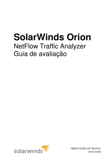
b.c.a.d.Figure 14. Collimating the optics. (a) When the mirrors are properly aligned, the view down the focuser drawtube should look like this. (b) Ifthe optics are out of alignment, the view might look something like this. (c) Here, the secondary mirror is centered under the focuser, but itneeds to be adjusted (tilted) so that the entire primary mirror is visible. (d) The secondary mirror is correctly aligned, but the primary mirrorstill needs adjustment. When the primary mirror is correctly aligned, the eye will be centered, as in (a).When putting the SkyQuest into a vehicle, common senseprevails. It is especially important that the optical tube doesnot knock around; this can cause the optics to become misaligned, and could dent the tube. We recommendtransporting and storing the tube assembly in a padded casefor proper protection.primary mirror, as in Figure 14a. If anything is off-center, as inFigure 14b, proceed with the following the collimation procedure.4. Collimation(Aligning The Mirrors)Use a Collimating ToolTo aid in centering your line of sight down the focuser drawtube,and in centering the mirror reflections during collimation, it is veryhelpful to use a precision collimating tool containing crosshairs,such as the Orion Collimating Eyepiece (#3640). We stronglyrecommend that you purchase one.Collimation is the process of adjusting the mirrors so they areperfectly aligned with one another.Your telescope’s optics werealigned at the factory, and should not need much adjustmentunless the telescope was handled roughly during shipment.Accurate alignment is important to ensure the peak performance of your telescope, so it should be checked regularly.Collimation is relatively easy to do and can be done in daylight.To check the collimation, remove the eyepiece and look down thefocuser drawtube.You should see the secondary mirror centeredin the drawtube as well as the reflection of the primary mirrorcentered in the secondary mirror, and the reflection of the secondary mirror (and your eye) centered in the reflection of the10It helps to put a piece of white paper on the inside of the opticaltube opposite the focuser. It forms a bright background behindthe secondary mirror, making it easier to distinguish the mirrorholder from the background.Alternatively, you can make a crude collimating tool out of anempty, black plastic 35mm film canister. It will not havecrosshairs, so it won’t be as precise, but it will be better thannothing. Cut 1/2" from the top lip of the canister and put a 1/16"to 1/8" diameter hole in the center of its bottom. The film canistercollimating tool goes into the focuser like an eyepiece, with thebottom end out.Aligning the Secondary MirrorWith eyepiece removed, look straight down the open focuserdrawtube at the secondary (diagonal) mirror. Ignore the
reflections for the time being. The secondary mirror itselfshould be centered in the focuser drawtube, in the directionparallel to the length of the telescope. If it isn’t, as in Figure14b, it must be adjusted. (It helps to adjust the secondary mirror in a brightly lit room with the telescope pointed toward abright surface, such as white
the unassembled Dobsonian base. Be careful unpacking the boxes.We recommend keeping the original shipping contain-ers. In the event that the telescope needs to be shipped to another location, or returned to Orion for warranty repair, hav-ing the proper shipping containers will help ensure that your telescope will survive the journey intact.