Transcription
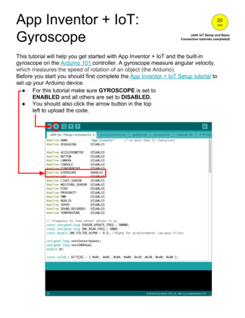
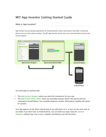
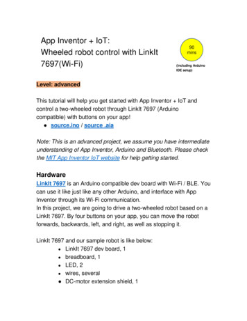
App Inventor IoT:Wheeled robot control with LinkIt7697(Wi-Fi)90mins(including ArduinoIDE setup)Level: advancedThis tutorial will help you get started with App Inventor IoT andcontrol a two-wheeled robot through LinkIt 7697 (Arduinocompatible) with buttons on your app! source.ino / source .aiaNote: This is an advanced project, we assume you have intermediateunderstanding of App Inventor, Arduino and Bluetooth. Please checkthe MIT App Inventor IoT website for help getting started.HardwareLinkIt 7697 is an Arduino compatible dev board with Wi-Fi / BLE. Youcan use it like just like any other Arduino, and interface with AppInventor through its Wi-Fi communication.In this project, we are going to drive a two-wheeled robot based on aLinkIt 7697. By four buttons on your app, you can move the robotforwards, backwards, left, and right, as well as stopping it.LinkIt 7697 and our sample robot is like below: LinkIt 7697 dev board, 1 breadboard, 1 LED, 2 wires, several DC-motor extension shield, 1
robot chassis (any version with 2 DC-motor and wheels)Arduino IDE Setup1. First, go to the Arduino IDE 1.8.x version. Download the .zipfile, unzip and click arduino.exe to open the IDE.2. From File Preference menu, enter the link below in theAdditional Boards Manager URLs field: http://download.labs.mediatek.com/package mtk linkit 7697 index.json
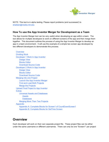
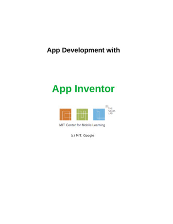
3. Open Tools/ Board/ Board Manager, then search "7697" andinstall the latest version of 7697 SDK.4. Download and install the CP2102N driver (Windows /MAC/OSX) , then check the COM port in your Device manager.Look for "Silicon Labs CP210 USB to UARTBridge(COMXX)", this is the COM port number of your LinkIt7697.5. For MAC users, it should be something like"/dev/tty.usbserialXXX " and forWindows users, pleasecheck the picture below:
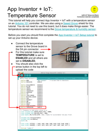
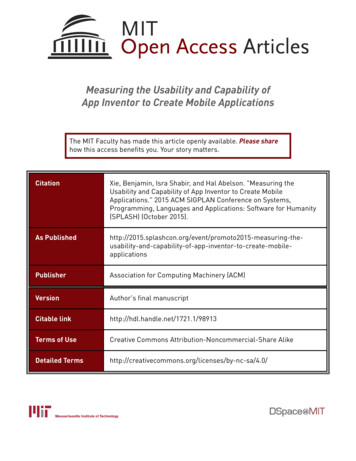
Hardware AssemblyHardware of this project is a bit complicated, we separated it intothree parts: LED headlights, motor drive circuit and chassis.1. LED headlightsOur robot has two LED as headlights. Your circuit should look likethe picture below, and please check the table for more details.LinkIt 7697LEDP13P12LED1 (left)LED2 (right)
GNDLED1 - / LED2 -2. Motor drive circuitWe recommend that you use a motor extension shield (like theArduino motor shield) rather than a single H-bridge DC-motorcontrol chip. Since motor shield has an integrated chip, you can savea lot of time with wiring. Additionally, the shield has protection for yourboard against surge. Any model of Arduino-compatible DC-motorshield should work fine with the LinkIt 7697.Arduino motor shieldYour circuit should look like the picture below, and please check thetable for more details. Please notice that you should power the motorshield and the microcontroller board with separate power, this isbecause the moment when the motor start rotating will need highercurrent and the microcontroller board may not be able to provideenough current and will reboot repeatedly.
DC Motor shieldENAMotor#1 (IN1)Motor#1-(IN2)Motor#2 (IN3)Motor#2-(IN4)ENB 12VGNDLinkIt 7697D11D10D9D8D7D6GND9V or 12V battery -3. Robot chassisFor the robot chassis, you can pick any kind of two-wheel chassis(two motors at each side with opposite directions). Here we listseveral of them: https://www.adafruit.com/product/3216 https://www.dfrobot.com/product-1144.html tbuilding-kit-for-Arduino-p-2843.html
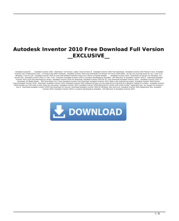
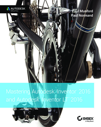
Here are some photos of our sample robot:
App InventorThe purpose of this project is to control the robot’s actions and LEDsvia Wi-Fi. The main idea is that App Inventor will open LinkIt 7697’sURL with different commands, this will light up the LED in differentcolors. /F: robot go forward /B: robot go backward /R: robot turn right /L: robot turn left /S: robot stop /l: left LED on/off /r: right LED on/offNow log in to your MIT App Inventor account and create a newproject.Designer1. The most used components in this project are buttons (totrigger actions) and labels (to show relevant messages).2. Add a TableArrangement component, set its width to Fillparent, height to 200 pixels, visible to false, Row to 2 andColumn to 3.3. For robot control, add four buttons into previousTableArrangement component. Give each a width of 33% anda height of 100 pixels. And modify the Text to " ", " ", " " and" ", representing different directions for the robot.4. For LED control, add two buttons to the previousTableArrangement component. Give each a width of 33% anda height of 100 pixels. And modify the Text to "L"and "R",representing the left and right LEDs.5. Add two labels, set their Text properties to "l / F / f" and "L / B /R" and visible to false. They are just reminders for each
button’s action.6. Add a Web component for sending text to LinkIt 7697 throughWi-Fi.After some adjusting, your designer should look similar to this. Itdoesn’t have to be exactly the same. Feel free to modify thecomponent’s background color, position and text size.BlocksLet’s take a look at our blocks step by step:1. Variable for Bluetooth addressPlease replace this with what you get from Arduino’s Serial Monitor(Open in toolbar or press Ctrl Shift m). This is LinkIt 7697’s IPaddress after connection to the Internet.
2. Setting the IPButton setIP is used to update the LinkIt 7697’s IP. This is veryconvenient when you want to control more than one LinkIt board.When you click the button (Button setIP.Click event), it will checkwhether the TextBox is empty. If so, then it will set the Textbox’scontent to the Web component’s Url (LinkIt 7697’s IP address). If not,it will show a message that tells the user to input LinkIt IP in the formof "XXX.XXX.XXX.XXX", such as "192.168.1.73".3. Procedure to update the Url of LinkIt 7697Here we use a procedure to manage what we send and updatethe message when we click each button. Please add aprocedure and click the blue gear to add two parameters.Rename this procedure to "sendData", and two parameters as"message" and "command.” The message parameter willupdate the label and the command parameter will senddifferent commands to LinkIt 7697.
The command parameter of the sendData procedure will becombined with the IP variable into a complete URL, like"http://192.168.1.73/R". The last letter is a different command sentto LinkIt 7697. Finally, we use the Web component to get this URL,by sending out a specific text to LinkIt 7697.4. Button to drive the robot forward and stopWhen each button is clicked, we are calling sendData procedureswith different parameters. Take Button Forward for example. theurl is "http://192.168.1.73/F" to drive robot go forward. And it is"http://192.168.1.73/S" to stop the robot, we are going to do exactlythe same situation as user finger is moved away from other threebuttons.Taking good advantage of the procedures will make your codesimply more readable and manageable.
5. Other buttons for robot actionsWhen we click the other buttons, we also use sendDataprocedures with different texts. This happens both when they arepressed (TouchDown event), and with the same text '/S' when userfinger is moved away.6. Buttons to control LEDFor the two buttons to control LEDs, we use sendDataprocedure with text '/l' and '/r' to toggle the two LEDs, whichmeans the first time we click the button will light up a LED, andnext time click the same button will light off.
Arduino codePlease download the code here and upload it to your LinkIt 7697.Press the "Upload" right-arrow button, this will compile and uploadthe Arduino sketch in Arduino IDE to your LinkIt 7697. Please makesure you see the "done uploading" message in the console below.TipsMake sure your LinkIt 7697 is running correctly as a Webserver.Open Serial Monitor in Arduino IDE, check the IP address of yourLinkIt 7697.Modify App Inventor’s IP variable value with this, then click eachbutton to get your robot going!
Brainstorming1. Add a Speechrecognizer component and use voice command todrive your robot like "go forward", "go backward", "turn left","turn right" and "stop". (reference: LED control tutorial)2. Note: the robot’s behavior depends on which platform you choose.Factors like chassis length, wheel, and motor torque are all goingto affect how your robot move. Try playing with different kinds ofrobot chassis (tank is good!) and adjust the code, you will discovermore!
understanding of App Inventor, Arduino and Bluetooth. Please check the MIT App Inventor IoT website for help getting started. Hardware LinkIt 7697 is an Arduino compatible dev board with Wi-Fi / BLE. You can use it like just like any other Arduino, and interface with App Inventor through its Wi-Fi communication.