Transcription
WELDING RESEARCHSUPPLEMENT TO THE WELDING JOURNAL, JULY 2002Sponsored by the American Welding Society and the Welding Research CouncilANSI/AWS A5.1-91 E6013 RutileElectrodes: The Effect of CalciteAll-weld-metal mechanical properties and microstructure, arc stability, andoperational characteristics were investigatedBY N. M. R. DE RISSONE, J. P. FARIAS, I. DE SOUZA BOTT, AND E. S. SURIANABSTRACT. This study is part of a program to obtain fundamental knowledgeabout rutile electrodes, of which information is scarce in international weldingliterature. In this investigation, three rutile-coated electrodes of the ANSI/AWSA5.1-91 E6013 type were prepared by increasing calcite (natural calcium carbonate — CaCO3), at the expense of cellulose and Si-bearing components, in theircoatings. This modification produced anincrease in the slag basicity, which causeda marked increment in all-weld-metaltoughness and slight modifications in operational behavior with a decrease in penetration and width of the weld bead, whilemaintaining the typical excellent operational characteristics of rutile electrodes.Arc stability studies were also performed.All-weld-metal hardness and tensileproperties were measured and metallographic studies undertaken.Introductiontries (Ref. 1). On the other hand, in LatinAmerica, almost 80% of deposited weldmetal is produced from this type of welding consumable (Ref. 2). In China andIndia, accompanying the noticeablegrowth of steel production, a marked increase of covered electrode use has beenobserved (Ref. 3). Everything seems toindicate the use of covered electrodes willstabilize in around 30% of the depositedweld metal (Ref. 1).Rutile-coated electrodes of the typesANSI/AWS A5.1-91 E6013 and E7024(Ref. 4) continue to be required. Largemanufacturers have replaced coveredelectrodes with solid and tubular continuous wires, but smaller ones still use covered electrodes for the following reasons(Ref. 2): Simplicity, durability, and low cost ofthe equipment required Possibility of being used in open andclosed locations The relative ease of finding welderswith the required skillDuring the decade of the 1980s, an important decrease in the use of coatedelectrodes took place in developed counN. M. R. DE RISSONE and E. S. SURIAN arewith the Center for Development and MaterialsTechnology, Facultad Regional San Nicolás,National Technology University, Buenos Aires,Argentina. J. P. FARIAS is with the Departmentof Mechanical Engineering and Production,Universidade Federal de Ceará, Fortaleza,Brazil. I. DE SOUZA BOTT is with the Department of Science, Materials and Metallurgy,Pontifícia Universidade Católica do Rio deJaneiro, Brazil.KEY WORDSCovered ElectrodesRutile CoatingBasic SlagSMAWCalcite AdditionsWeldability Wide range of consumables for mostapplications, which is a function of thequick setup fabrication Availability in small units at relatively low cost. (It is generally acceptedwelding consumables represent 1–2 %of the final cost in overall fabrication).As for covered electrodes for the deposition of C-Mn steels, a lot of researchconducted during the last 20 years hasbeen to increase knowledge of basic covered electrodes of types E7018 (Refs. 5,6) and E7016 (Refs. 7, 8). This is not thecase with rutile electrodes. At present,few papers about this type of consumablehave been published (Refs. 9–23).Since welding consumable manufacturers produce larger quantities of rutilecoated electrodes than basic ones and therutile type is technically more importantthan the basic, more complete information about rutile electrodes should begenerated for the following reasons:1) The requirements of internationalclassification societies (ABS, BV, DnV,LRS) establish three grades for the classification of rutile electrodes (Ref. 24) according to the temperature at which 47 Jminimum, on average, is obtained fromthe Charpy V-notch impacts. They areGrade 1 20 C (68 F), Grade 2 0 C(32 F), and Grade 3 –20 C (–4 F) demanding 33 J minimum for each individual value. Grade 3 is normally requiredfor the naval industry, so it is technicallyimportant. Not all covered electrodemanufacturers have adequate knowledgeto consistently satisfy the requirements ofthe grades mentioned.WELDING JOURNAL 113-S
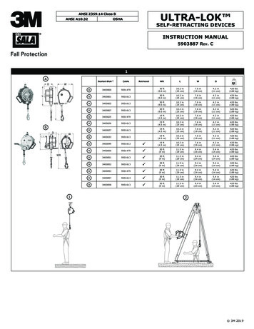
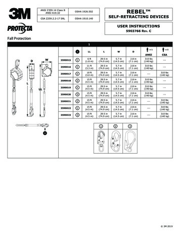
WELDING RESEARCHFig. 1 — All-weld-metal assembly according to ISO 2560 standard.Fig. 2 — Cross section of the all-weld-metal test assembly.Table 1 — Coating Composition and SlagChemical Analysis (wt-%)CoatingDry MixConstituentsTiO2SiO2 Al2O3from(a)CaCO3CelluloseMn FeK2O from(a)CaOFeOAl2O3SiO2MnOTiO2Na2OK2OBasicity Index(Ref. 50.53(a) Si-bearing materials: quartz, kaolin, mica, and feldspar.Table 2 — Welding Parameters Used for theISO2560 Test Specimens Welded with DC(–)Parameters5Calcite10Calcite15CalciteCurrent (A)Voltage (V)Welding speed(mm/s)Heat input(kJ/mm)180223.7200193.6210173.11.11.11.22) Underwater wet welding has received great interest. Because rutile electrodes are used for this purpose (Refs.25–26), it is necessary to generate knowledge about them.3) All-position, flux cored welding114-S JULY 2002wires are rutile (Ref. 27), as is their slag(it is possible to achieve diffusible hydrogen content under 5 mL/100 g of deposited metal). Basic metallurgicalknowledge about rutile electrodes couldbe obtained in a cheaper and simpler waywith covered electrodes, then transferredto tubular wires, as has been done withE7018 basic-coated electrodes.For these reasons, a research programwith covered electrodes of the E6013 typehas been developed. This program studied the effect that slag basicity variation,through increasing the calcite coatingcontent, has on the operational characteristics, arc stability, and all-weld-metalproperties.Operational Properties: Manual WeldingExperimental ProcedureThe operational behavior of the threeelectrodes was studied using an AC-DC350-A power supply set to AC, alternating current; DC( ), direct current, positive pole to the electrode; and DC(–), direct current, negative pole to theelectrode; in flat (F), horizontal fillet(HF), and vertical uphill fillet (VUF) positions; and in vertical downhill (VD) position only on AC.It was noted as coating calcite increased, it was necessary to increase thecurrent to achieve appropriate operational properties in the flat position. Voltage decreased with increased calcite.Table 2 presents the welding parametersfor the flat welding position.ElectrodesAll-Weld-Metal Test AssembliesThree electrodes with a 4-mm diameter and coating factor (coating diameter:wire diameter) of 1.5 were designed by increasing calcite (natural calcium carbonate-CaCO3) from 5 to 15 wt-% at the expense of cellulose and Si-bearing rawmaterials (quartz, kaolin, mica, andfeldspar) in the dry mix. This replacementwas undertaken to obtain an increase inbasicity of the slag without varying TiO2content to maintain the operational characteristics of the rutile electrodes as far aspossible. All the electrodes were produced with the same quantity of potassium silicate and the same wire and powder raw material batches. The coating drymix composition and the slag chemicalanalyses, with the corresponding basicityindexes (BI) calculated according to Boniszewski (Ref. 28) are shown in Table 1.In all tables and/or figures, the electrodes will be identified as 5-calcite, 10calcite, or 15-calcite, depending on thepercentage of calcite in the electrodecoating (Table 1).All-weld-metal test assemblies withthree passes per layer (a total of nine) according to ISO 2560-73 standard (Ref.29) (Fig. 1) were manually welded in theflat position, applying DC(–) using theequipment previously mentioned. Thebase material was ASTM A36. Table 2shows the welding parameters employed.Chemical CompositionChemical analyses were obtainedfrom both the transversal cut samples extracted from the all-weld-metal coupons,welded on DC(–), and from the weldpads, welded on both AC and DC( ), according to ANSI/AWS A5.1-91 (Ref. 4).The base material was ASTM A36.Metallographic StudyThe metallographic study was carriedout on transverse cross sections of the allweld-metal test assemblies — Fig. 2. Thepercentages of columnar and reheated
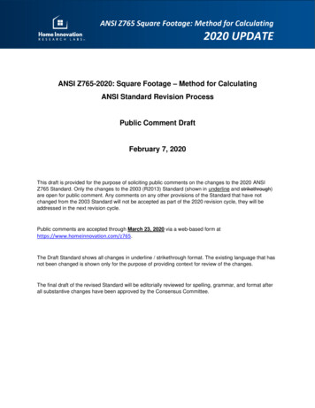
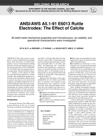
WELDING RESEARCHFig. 3 — Automatic welding equipment.zones were measured at 500X at theCharpy V-notch location. The averagewidth of the columnar grain size (theprior austenite grains) was measured inthe top bead of the samples at 100X.To quantify the microstructural constituents of the columnar zones in eachweld, 30 fields of 100 points were measured in the top bead at 500X by light optical microscopy, according to Ref. 30.The reheated fine grain size was measured in the heat-affected zone of the topbead, according to the linear interceptmethod (ASTM E112 standard).Inclusion analysis was carried outusing scanning electron microscopy(SEM). The inclusion chemical composition was determined using energy dispersive spectrometry (EDS) through semiquantitative measurements. Inclusionswith diameters higher than 2 micronswere selected. The percentage of eachoxide was calculated by stoichiometryfrom the EDS measurements taking therelative quantities of each element foundwith the system used (Ti, Al, Si, and M),considering their sum was 100%.Mechanical TestingMicrohardness was determined on thetransverse cross section of the all-weldmetal test assemblies at the Charpy Vnotch location (Fig. 2) using the Vickers1000-g scale.From each all-weld-metal test assembly, a Minitrac (Ref. 31) test specimen(total length 55 mm, gauge length 25mm, reduced section diameter 5 mm,ratio of gauge length to diameter 5:1)was extracted (Fig. 2), as well as sufficientFig. 4 — The cup, the arc length, and the visible arc length.Fig. 5 — Beads obtained in the flat position welding with AC.Charpy V-notch impact specimens to construct the absorbed energy vs. test temperature curve between 20 C (68 F) and–40 C (–40 F). Tensile property test specimens were tested at room temperature.Arc Stability StudyWith the electrodes described in Table1, bead-on-plate welds in the flat positionwith AC, DC( ), and DC(–) on 50 x 150x 8 mm ASTM A-36 steel plates were deposited using an automated test benchwith computerized data acquisition asshown schematically in Fig. 3. The automated test bench consisted of a 350-A in-verter, constant power supply with 65 Vof open voltage (item 9 of Fig. 3), and anautomated welding system developedthrough a cooperative research projectbetween the Engineering Welding Laboratory (ENGESOLDA) and the Controland Instrumentation Laboratory (LIC)of the Federal University of Ceará,Brazil. This system has a card control(item 3 of Fig. 3) that uses arc voltage tocontrol arc length. Once a voltage variation occurs in the arc, the card controlchanges the voltage signals sent to themotor (item 1 of Fig. 3), which in turn alters its rotation and consequently thefeed velocity of the electrode (item 4 ofWELDING JOURNAL 115-S
WELDING RESEARCHments, are described in the Appendix.The study of arc behavior was basedon a methodology that evaluated arc stability, assessed by considering both theelectric charge transfer and metal transfer mechanisms (Refs. 32, 33). All the results were submitted to a variance analysis (Ref. 34), with a confidence level of95%, for determination of the significance level (α) of the analyzed effects. Inthis study, α 5.0% was considered forcomparing average values.Electric Charge Transfer MechanismThe ease of electric charge transferwas evaluated by considering the indexFE1 with DC, and the index B with AC.FE1 Fig. 6 — Beads obtained in vertical uphill position welding with AC.Parameters5-Calcite10-CalciteCurrent reMeanRoot-mean-squareWelding Speed(mm/s)Fig. 3). The welding speed is selected directly by a travel carriage (item 2 ofFig. 3) and kept constant.The components of the data acquisition system were a sensor hall of 300 A(item 5 of Fig. 3), a signal processing circuit, an A/D converter (item 6 of Fig. 3),a microcomputer (item 7 of Fig. 3), and aprinter (item 8 of Fig. 3). This acquisitiondata system allowed current and voltagereading at programmable frequencies upto 10 Hz at 12 bits per channel.The simulator controlled the arc voltage in order to weld with the same visiblearc length in all experiments. The arclength in turn was controlled via the voltage. The simulator does not measure thearc length but the voltage. The arc lengthwas established for each electrode priorto welding using a calibration curve (voltage vs. arc length). In order to obtain thiscalibration curve, different current conditions and arc lengths were used. The arc116-S JULY 2002DC(-)1601611601611641642020191916162.9Type of CurrentDC( )1641641661671671682021191916172.9 2000(P P ) t101 -1 1 W s (1)FE1 is the inverse of the restriking meanenergy after the short circuit occurrencewith DC welding. (E1, P1, P0, and t1 aredefined in the Appendix.)Table 3 — Welding Parameters for the Arc Stability 172.9was projected by means of lenses on ascreen with a measurement scale, allowing the arc length to be determined. Oncethe arc length was determined, the calibration curve indicated the arc voltagevalue, which in turn was adjusted via thecontrol card of the simulator and keptconstant during the whole procedure.Each experiment, conducted according to the welding parameters listed inTable 3, was undertaken in triplicate. Theinstantaneous values of arc voltage andcurrent were registered for periods of 6 s,totalling 18 s of acquisition for each combination of electrode/current type. To undertake a behavior analysis, a dedicatedsoftware (ANALYSER) was used fortreating the instantaneous voltage andcurrent signals acquired (Ref. 32
tile-coated electrodes of the ANSI/AWS A5.1-91 E6013 type were prepared by in-creasing calcite (natural calcium carbon-ate — CaCO 3), at the expense of cellu-lose and Si-bearing components, in their coatings. This modification produced an increase in the slag basicity, which caused a