Transcription
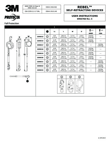
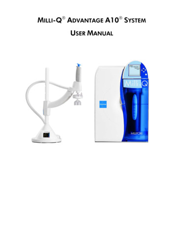
Ultra-Lok ANSI Z359.14 Class BANSI A10.32OSHASelf-Retracting DeviceSINSTRUCTION MANUAL5903887 Rev. C1ASealed-Blok DCableRetrievalWRLWDWLWRBDWLWR1A3400800950147930 ft(9.0 m)10.2 in(25 cm)7.6 in(19 cm)4.3 in(11 cm)420 lbs(189 kg)A3400801950161330 ft(9.0 m)10.2 in(25 cm)7.6 in(19 cm)4.3 in(11 cm)420 lbs(189 kg)A3400802950161330 ft(9.0 m)10.2 in(25 cm)7.6 in(19 cm)4.3 in(11 cm)420 lbs(189 kg)A3400807950161330 ft(9.0 m)10.2 in(25 cm)7.6 in(19 cm)4.3 in(11 cm)420 lbs(189 kg)A3400825950147915 ft(4.5 m)10.2 in(25 cm)7.6 in(19 cm)4.3 in(11 cm)420 lbs(189 kg)10.2 in(25 cm)7.6 in(19 cm)4.3 in(11 cm)420 lbs(189 kg)A3400826950161315 ft(4.5 m)A3400827950161315 ft(4.5 m)10.2 in(25 cm)7.6 in(19 cm)4.3 in(11 cm)420 lbs(189 kg)A3400833950161315 ft(4.5 m)10.2 in(25 cm)7.6 in(19 cm)4.3 in(11 cm)420 lbs(189 kg)A34008499501613ü15 ft(4.5 m)10.2 in(25 cm)7.6 in(19 cm)4.3 in(11 cm)420 lbs(189 kg)A34008509501479ü30 ft(9 m)11.5 in(29 cm)9.4 in(24 cm)5.4 in(14 cm)420 lbs(189 kg)A34008519501613ü30 ft(9 m)11.5 in(29 cm)9.4 in(24 cm)5.4 in(14 cm)420 lbs(189 kg)A34008529501613ü30 ft(9 m)11.5 in(29 cm)9.4 in(24 cm)5.4 in(14 cm)420 lbs(189 kg)A34008539501479ü30 ft(9 m)11.5 in(29 cm)9.4 in(24 cm)5.4 in(14 cm)420 lbs(189 kg)A34008579501613ü30 ft(9 m)11.5 in(29 cm)9.4 in(24 cm)5.4 in(14 cm)420 lbs(189 kg)B34008589501613ü30 ft(9 m)11.5 in(29 cm)9.4 in(24 cm)5.4 in(14 cm)420 lbs(189 kg)2 3M 2019
2FCBGAED3ABCHFFFCDDSFFC FF DD SF2FC
4FCFCft )7.4(2.4)7.3(2.4)7.2(2.3)7.2(2.4)7.1(2.3)7(2.3)
7BA8BDAAACCBBCBABC91234
1012345A1112B5B1314BAAACCAüûBCDA5
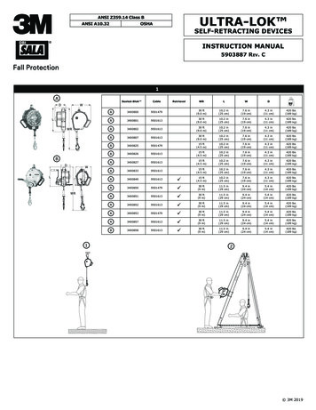
1516BDAAC17AACDFBEBAFHDWARNINGGEDEC9502313 Rev. DFGH30’ (9 m) SRDs only.6
SIT 5908239 BSAFETY INFORMATIONENPlease read, understand, and follow all safety information contained in these instructions prior to the use of this Self-RetractingDevice (SRD). FAILURE TO DO SO COULD RESULT IN SERIOUS INJURY OR DEATH.These instructions must be provided to the user of this equipment. Retain these instructions for future reference.Intended Use:This Self-Retracting Device is intended for use as part of a complete personal fall protection system.Use in any other application including, but not limited to, material handling, recreational or sports related activities, or other activities notdescribed in the User Instructions, is not approved by 3M and could result in serious injury or death.This device is only to be used by trained users in workplace applications.!!WARNINGThis Self-Retracting Device is part of a personal fall protection system. It is expected that all users be fully trained in the safe installation andoperation of their personal fall protection system. Misuse of this device could result in serious injury or death. For proper selection,operation, installation, maintenance, and service, refer to these User Instructions including all manufacturer recommendations, see yoursupervisor, or contact 3M Technical Services. To reduce the risks associated with working with an SRD which, if not avoided, could result in serious injury or death:------------ Before each use, inspect the SRD and check for proper locking and retraction.If inspection reveals an unsafe or defective condition, remove the device from service and repair or replace according to the UserInstructions.If the SRD has been subjected to fall arrest or impact force, immediately remove the SRD from service and label the device ‘UNUSABLE’.Ensure the lifeline is kept free from any and all obstructions including, but not limited to; entanglement with moving machinery orequipment (e.g., the top drive of oil rigs), other workers, yourself, surrounding objects, or impact from overhead objects that could fallonto the lifeline or the worker.Never allow slack in the lifeline. Do not tie or knot the lifeline.Attach the unused leg(s) of the Harness Mounted SRD to the parking attachment(s) of the harness if equipped.Do not use in applications that have an obstructed fall path. Working on slowly shifting material, such as sand or grain, or within confinedor cramped spaces, may not allow the worker to reach sufficient speed to cause the SRD to lock. A clear path is required to assurepositive locking of the SRD.Avoid sudden or quick movements during normal work operation. This may cause the device to lock up.Ensure that fall protection systems/subsystems assembled from components made by different manufacturers are compatible and meetthe requirements of applicable standards, including the ANSI Z359 or other applicable fall protection codes, standards, or requirements.Always consult a Competent and/or Qualified Person before using these systems.To reduce the risks associated with working at height which, if not avoided, could result in serious injury or death:-------------------Ensure your health and physical condition allow you to safely withstand all of the forces associated with working at height. Consult withyour doctor if you have any questions regarding your ability to use this equipment.Never exceed allowable capacity of your fall protection equipment.Never exceed maximum free fall distance of your fall protection equipment.Do not use any fall protection equipment that fails pre-use or other scheduled inspections, or if you have concerns about the use orsuitability of the equipment for your application. Contact 3M Technical Services with any questions.Some subsystem and component combinations may interfere with the operation of this equipment. Only use compatible connections.Consult 3M prior to using this equipment in combination with components or subsystems other than those described in the UserInstructions.Use extra precautions when working around moving machinery (e.g. top drive of oil rigs) electrical hazards, extreme temperatures,chemical hazards, explosive or toxic gases, sharp edges, or below overhead materials that could fall onto you or your fall protectionequipment.Use Arc Flash or Hot Works devices when working in high heat environments.Avoid surfaces and objects that can damage the user or equipment.Ensure there is adequate fall clearance when working at height.Never modify or alter your fall protection equipment. Only 3M or parties authorized in writing by 3M may make repairs to the equipment.Prior to use of fall protection equipment, ensure a rescue plan is in place which allows for prompt rescue if a fall incident occurs.If a fall incident occurs, immediately seek medical attention for the worker who has fallen.Do not use a body belt for fall arrest applications. Use only a Full Body Harness.Minimize swing falls by working as directly below the anchorage point as possible.If training with this device, a secondary fall protection system must be utilized in a manner that does not expose the trainee to anunintended fall hazard.Always wear appropriate personal protective equipment when installing, using, or inspecting the device/system.7
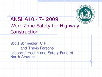
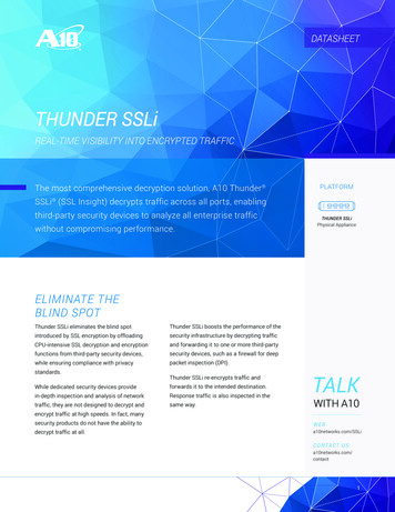
;;Before using this equipment, record the product identification information from the ID label in the ‘Inspection andMaintenance Log’ at the back of this manual.;;Always ensure you are using the latest revision of your 3M instruction manual. Visit the 3m website or contact 3MTechnical Services for updated instruction manuals.DESCRIPTION:Figure 2 identifies key components of the DBI-SALA Ultra-Lok Self-Retracting Devices (SRDs). Ultra-Lok SRDs are drumwound Wire Rope Lifelines (A) which retract into a sealed aluminum Housing (B). They can hang from anchorage by a Carabinerattached through the Swivel Eye (C) on the top of the SRD. A Self-Locking Snap Hook (D) on the end of the Lifeline attaches tothe designated Fall Arrest connection on a Full Body Harness. A Bumper (E), protects the Wire Rope and Ferrules securing theSnap Hook from abrasion and corrosion.Figure 1 defines the Ultra-Lok SRD models covered by this instruction manual. The following SRD Types are available: Self-Retracting Device (1): Self-Retracting Devices (SRDs) are suitable for applications where the lifeline remainsgenerally vertical during use and possible Free Fall is limited to 2 ft (0.6 m). Self-Retracting Device with Rescue (2): Self-Retracting Devices with Rescue include an integral means for assistedrescue by raising or lowering the rescue subject. RSRDs are equipped with a 3-Way Emergency Retrieval Hand Crank(F). Some models include a Tripod Mounting Bracket (G) to mount the SRD on the leg of a Tripod for Confined Spaceapplications.Table 1 - SpecificationsMaterialGate StrengthThroat Size2000180HookSwiveling Self-Locking Snap Hook with ImpactIndicatorDescriptionAlloy Steel3,600 lbs (16 kN)3/4 in (1.9 cm)2000181Swiveling Self-Locking Snap Hook with ImpactIndicatorStainless Steel3,600 lbs (16 kN)3/4 in (1.9 cm)Maximum Arrest Force:900 lbs (4 kN)Average Arrest Force:900 lbs (4 kN)Maximum Arrest Distance:42 in (1.1 m)Average Locking Speed:4.5 ft/s (1.4 m/s)LifelineMaterialDiameterMinimum TensileStrength9501479Galvanized Steel Wire Rope3/16 in. (4.76 mm)4,200 lbs (18.7 kN)9501613Stainless Steel Wire Rope3/16 in. (4.76 mm)3,600 lbs (16.0 kN)8
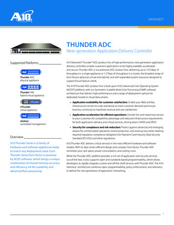
1.0 APPLICATIONS1.1PURPOSE: Self-Retracting Devices (SRDs) are designed to be a component in a personal fall arrest system (PFAS). Figure1 illustrates SRDs covered by this instruction manual. They may be used in most situations where a combination of workermobility and fall protection is required (i.e. inspection work, general construction, maintenance work, oil production,confined space work, etc.).1.2STANDARDS: Your SRD conforms to the national or regional standard(s) identified on the front cover of theseinstructions. Refer to the local, state, and federal (OSHA) requirements governing occupational safety for additionalinformation regarding Personal Fall Protection.1.3TRAINING: This equipment is intended to be used by persons trained in its correct application and use. It is theresponsibility of the user to assure they are familiar with these instructions and are trained in the correct care and useof this equipment. Users must also be aware of the operating characteristics, application limits, and the consequences ofimproper use.1.4LIMITATIONS: Always consider the following limitations when installing or using this equipment: Capacity: SRDs are for use by one person with a combined weight (clothing, tools, etc.) meeting the Capacity Rangespecified in Table 1 for your standard(s). Make sure all of the components in your system are rated to a capacityappropriate to your application. Anchorage: Anchorages selected for fall arrest systems shall have a strength capable of sustaining static loadsapplied in the directions permitted by the system of at least:1.2.5,000 lbs. (22.2 kN) for non-certified anchorages, orTwo times the maximum arresting force for certified anchorages.When more than one fall arrest system is attached to an anchorage, the strengths set forth in (1) and (2) above shallbe multiplied by the number of systems attached to the anchorage.FROM OSHA 1926.502 AND 1910.140: Anchorages used for attachment of personal fall arrest systems shall beindependent of any anchorage being used to support or suspend platforms, and capable of supporting at least 5,000 lbs.per user attached, or be designed, installed, and used as part of a complete personal fall arrest systems which maintainsa safety factor of at least two, and is under the supervision of a qualified person. Locking Speed: Situations which do not allow for an unobstructed fall path should be avoided. Working in confinedor cramped spaces may not allow the body to reach sufficient speed to cause the SRD to lock if a fall occurs. Workingon slowly shifting material, such as sand or grain,may not allow enough speed buildup to cause the SRD to lock. Aclear path is required to assure positive locking of the SRD. Free Fall: Properly using an SRD in overhead applications will minimize free fall distance. To prevent an increased free falldistance, follow the instructions below: Never clamp, knot, or otherwise prevent the lifeline from retracting or staying taut.Avoid any slack in the lifeline of the SRD.Do not work above the level of your anchorage.Do not lengthen SRDs by connecting a lanyard or similar component without consulting 3M.For product-specific information relating to free fall and fall clearance values, please refer to Table 1 of thisinstruction. Swing Falls: Swing Falls occur when the anchorage point is not directly above the point where a fall occurs. Theforce of striking an obje
the requirements of applicable standards, including the ANSI Z359 or other applicable fall protection codes, standards, or requirements. Always consult a Competent