Transcription
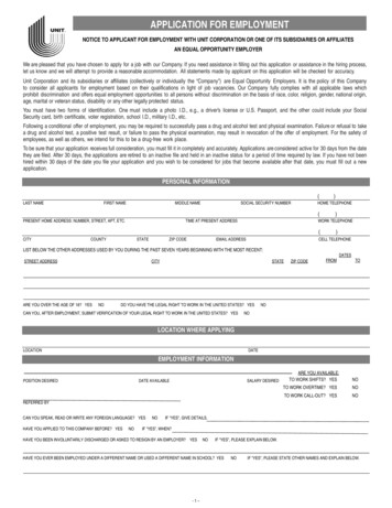
ProductFolderOrderNowTechnicalDocumentsSupport &CommunityTools &SoftwareSN74LVC2G241SCES210P – APRIL 1999 – REVISED JANUARY 2019SN74LVC2G241 Dual Buffer and Driver With 3-State Outputs1 Features3 Description This dual buffer and line driver is designed for 1.65-Vto 5.5-V VCC operation.1 Available in the Texas InstrumentsNanoFree PackageSupports 5-V VCC OperationInputs Accept Voltages to 5.5 VMax tpd of 4.1 ns at 3.3 VLow Power Consumption, 10-µA Maximum ICC 24-mA Output Drive at 3.3 VTypical VOLP (Output Ground Bounce) 0.8 V at VCC 3.3 V, TA 25 CTypical VOHV (Output VOH Undershoot) 2 V at VCC 3.3 V, TA 25 CIoff Supports Live Insertion, Partial-Power-DownMode, and Back-Drive ProtectionCan Be Used as a Down Translator to TranslateInputs From a Max of 5.5 V Downto the VCC LevelLatch-Up Performance Exceeds 100 mA PerJESD 78, Class IIESD Protection Exceeds JESD 22– 2000-V Human-Body Model (A114-A)– 200-V Machine Model (A115-A)– 1000-V Charged-Device Model (C101)The SN74LVC2G241 device is designed specificallyto improve both the performance and density of 3state memory-address drivers, clock drivers, and busoriented receivers and transmitters.NanoFree package technology is a majorbreakthrough in IC packaging concepts, using the dieas the package.The SN74LVC2G241 device is organized as two 1-bitline drivers with separate output-enable (1OE, 2OE)inputs. When 1OE is low and 2OE is high, the devicepasses data from the A inputs to the Y outputs. When1OE is high and 2OE is low, the outputs are in thehigh-impedance state.To ensure the high-impedance state during power upor power down, OE should be tied to VCC through apullup resistor, and OE should be tied to GNDthrough a pulldown resistor; the minimum value of theresistor is determined by the current-sinking or thecurrent-sourcing capability of the driver.This device is fully specified for partial-power-downapplications using Ioff. The Ioff circuitry disables theoutputs, preventing damaging current backflowthrough the device when it is powered down.2 Applications AV ReceiversBlu-ray Players and Home TheatersDVD Recorders and PlayersDesktop or Notebook PCsDigital Radio or Internet Radio PlayersDigital Video Cameras (DVC)Embedded PCsGPS: Personal Navigation DevicesMobile Internet DevicesNetwork Projector Front-EndsPortable Media PlayersPro Audio MixersDevice Information(1)PART NUMBERPACKAGESN74LVC2G241DCTSM8 (8)BODY SIZE (NOM)2.95 mm 2.80 mmSN74LVC2G241DCU VSOOP (8)2.30 mm 2.00 mmSN74LVC2G241YZP1.91 mm 0.91 mmDSBGA (8)(1) For all available packages, see the orderable addendum atthe end of the data sheet.Logic Diagram (Positive Logic)1OE1A2OE2A1261Y7532Y1An IMPORTANT NOTICE at the end of this data sheet addresses availability, warranty, changes, use in safety-critical applications,intellectual property matters and other important disclaimers. PRODUCTION DATA.
SN74LVC2G241SCES210P – APRIL 1999 – REVISED JANUARY 2019www.ti.comTable of Contents12345678Features .Applications .Description .Revision History.Pin Configuration and Functions 5666Absolute Maximum Ratings .ESD Ratings.Recommended Operating Conditions .Thermal Information .Electrical Characteristics.Switching Characteristics .Operating Characteristics.Typical Characteristic.Parameter Measurement Information . 7Detailed Description . 88.1 Overview . 88.2 Functional Block Diagram . 88.3 Feature Description. 88.4 Device Functional Modes. 89Application and Implementation . 99.1 Application Information. 99.2 Typical Application . 910 Power Supply Recommendations . 1011 Layout. 1011.1 Layout Guidelines . 1011.2 Layout Example . 1012 Device and Documentation Support . 1112.112.212.312.412.5Documentation Support .Community Resources.Trademarks .Electrostatic Discharge Caution .Glossary .111111111113 Mechanical, Packaging, and OrderableInformation . 114 Revision HistoryNOTE: Page numbers for previous revisions may differ from page numbers in the current version.Changes from Revision O (December 2015) to Revision PPage Changed Electrical Characteristics table format . 5 Changed Switching Characteristics tables format. . 6Changes from Revision N (November 2013) to Revision O PageAdded Applications section, Device Information table, ESD Ratings table, Thermal Information table, TypicalCharacteristics, Feature Description section, Device Functional Modes, Application and Implementation section,Power Supply Recommendations section, Layout section, Device and Documentation Support section, andMechanical, Packaging, and Orderable Information section. . 1Changes from Revision M (February 2007) to Revision NPage Updated document to new TI data sheet format. . 1 Removed Ordering Information table. . 1 Updated Features. . 1 Updated operating temperature range. . 42Submit Documentation FeedbackCopyright 1999–2019, Texas Instruments IncorporatedProduct Folder Links: SN74LVC2G241
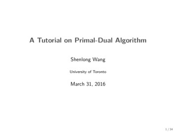
SN74LVC2G241www.ti.comSCES210P – APRIL 1999 – REVISED JANUARY 20195 Pin Configuration and FunctionsDCT Package8-Pin SM8Top View1OE1DCU Package8-Pin VSSOPTop 2A3645YZP Package8-Pin DSBGABottom ViewGND2Y1A1OE4 53 62 71 82A1Y2OEVCCPin Functions (1) (2)PINNAMENO.1A21OE1YI/ODESCRIPTIONIInput1IOutput enable (Active low)6OOutput2A5IInput2Y3OOutput2OE7IOutput enable (Active high)GND4—GroundVCC8—Power pin(1)(2)N.C. – No internal connectionSee for dimensionsSubmit Documentation FeedbackCopyright 1999–2019, Texas Instruments IncorporatedProduct Folder Links: SN74LVC2G2413
SN74LVC2G241SCES210P – APRIL 1999 – REVISED JANUARY 2019www.ti.com6 Specifications6.1 Absolute Maximum Ratingsover operating free-air temperature range (unless otherwise noted) (1)VCCMINMAXUNITSupply voltage–0.56.5V(2)VIInput voltage–0.56.5VVOVoltage applied to any output in the high-impedance or power-off state (2)–0.56.5VVOVoltage applied to any output in the high or low state (2) (3)–0.5VCC 0.5VIIKInput clamp currentVI 0–50mAIOKOutput clamp currentVO 0–50mAIOContinuous output current 50mAContinuous current through VCC or GND 100mATJMaximum junction temperature150 CTstgStorage temperature150 C(1)(2)(3)–65Stresses beyond those listed under Absolute Maximum Ratings may cause permanent damage to the device. These are stress ratingsonly, and functional operation of the device at these or any other conditions beyond those indicated under Recommended OperatingConditions is not implied. Exposure to absolute-maximum-rated conditions for extended periods may affect device reliability.The input negative-voltage and output voltage ratings may be exceeded if the input and output current ratings are observed.The value of VCC is provided in the Recommended Operating Conditions table.6.2 ESD n-body model (HBM), per ANSI/ESDA/JEDEC JS-001, all pins(1)UNIT 2000Charged-device model (CDM), per JEDEC specification JESD22-C101, allpins (2)V 1000JEDEC document JEP155 states that 500-V HBM allows safe manufacturing with a standard ESD control process.JEDEC document JEP157 states that 250-V CDM allows safe manufacturing with a standard ESD control process.6.3 Recommended Operating Conditions (1)VCCSupply voltageOperatingData retention onlyVCC 1.65 V to 1.95 VVIHHigh-level input voltageVCC 2.3 V to 2.7 VVCC 3 V to 3.6 VVCC 4.5 V to 5.5 VMINMAX1.655.51.5Low-level input voltageVIInput voltage1.7Output voltage0.7 VCC0.35 VCCVCC 2.3 V to 2.7 V0.7VCC 3 V to 3.6 V0.85.5High or low state0VCC3-state05.5VCC 2.3 VHigh-level output currentVCC 3 VVCC 4.5 V(1)4V0.3 VCC0VCC 1.65 VIOHV2VCC 4.5 V to 5.5 VVOV0.65 VCCVCC 1.65 V to 1.95 VVILUNITVV–4–8–16mA–24–32All unused inputs of the device must be held at VCC or GND to ensure proper device operation. Refer to the TI application reportImplications of Slow or Floating CMOS Inputs, SCBA004.Submit Documentation FeedbackCopyright 1999–2019, Texas Instruments IncorporatedProduct Folder Links: SN74LVC2G241
SN74LVC2G241www.ti.comSCES210P – APRIL 1999 – REVISED JANUARY 2019Recommended Operating Conditions(1) (continued)MINIOLLow-level output currentMAXVCC 1.65 V4VCC 2.3 V816VCC 3 VΔt/Δv Input transition rise or fall ratemA24VCC 4.5 V32VCC 1.8 V 0.15 V, 2.5 V 0.2 V20VCC 3.3 V 0.3 V10VCC 5 V 0.5 VTAUNITns/V5Operating free-air temperature–4085 C6.4 Thermal InformationSN74LVC2G241THERMAL METRIC (1)RθJA(1)Junction-to-ambient thermal resistanceDCT(SM8)DCU(VSSOP)YZP(DSBGA)8 PINS8 PINS8 PINS220227102UNIT C/WFor more information about traditional and new thermal metrics, see the Semiconductor and IC Package Thermal Metrics applicationreport, SPRA953.6.5 Electrical Characteristicsover recommended operating free-air temperature range, TA –40ºC to 125 C (unless otherwise noted)PARAMETERTEST CONDITIONSVCCMINIOH –100 µAVOH1.65 V to 5.5 VMINVCC – 0.1VCC – 0.11.21
over operating free-air temperature range (unless otherwise noted)(1) MIN MAX UNIT VCC Supply voltage -0.5 6.5 V VI Input voltage(2) -0.5 6.5 V VO Voltage applied to any output in the high-impedance or power-off state(2) -0.5 6.5 V VO Voltage applied to any output in the high or low state(2)(3) -0.5 VCC 0.5 V IIK Input clamp current .