Transcription
Handbook of PVC Pipe Design and ConstructionCHAPTER12PVC NonpressurePipe InstallationTrench Construction Pipe Laying System Components Inspection and Testingof the Pipe SystemCopyright 2012, Industrial Press Inc., New York, NY - http://industrialpress.comCommittee PVC 12.indd 12.120/11/12 10:37 PM
Handbook of PVC Pipe Design and Construction12.2Chapter 12Table of Contents12.1 Notation . 12.312.2 Introduction . 12.312.3 Trench Construction. 12.412.3.1 Minimum Trench Width .12.412.3.2 Movable Sheeting, Trench Boxes, or Shields.12.612.3.3 Dewatering.12.712.3.4 Preparation of Trench Bottom.12.812.4 Pipe Laying. 12.912.4.1 Bedding.12.1012.4.2 Haunching .12.1012.4.3 Initial Backfill.12.1012.4.4 Final Backfill .12.1112.4.5 Embedment Materials.12.1312.4.5.1 Class I Materials.12.1312.4.5.2 Class II Materials .12.1312.4.5.3 Class III Materials .12.1312.4.5.4 Class IV Materials.12.1612.4.6 Migration .12.1612.4.7 Embedment Compaction .12.1712.4.8 Common Trenches.12.1812.4.9 Sewers on Steep Slopes.12.1912.4.10 Recommended Embedment Densities.12.1912.5 System Components . 12.2012.5.1 Fittings.12.2012.5.2 Service Lines .12.21Copyright 2012, Industrial Press Inc., New York, NY - http://industrialpress.comCommittee PVC 12.indd 12.220/11/12 10:37 PM
Handbook of PVC Pipe Design and ConstructionPVC Nonpressure Pipe Installation12.312.5.3 Pipe Caps and Plugs .12.2212.5.4 Risers .12.2312.5.5 Manholes and Junctions .12.2412.6 Inspection and Testing of the Pipe System. 12.2912.6.1 Precleaning .12.2912.6.2 Visual Inspection .12.2912.6.3 Leakage Testing.12.3012.6.3.1 Air Testing .12.3012.6.3.2 Infiltration/Exfiltration Testing .12.3012.6.4 Deflection Testing.12.3012.7 Sources . 12.3512.1 NotationA 5 OD tolerance (ASTM D3034 or F679), in.B 5 excess wall thickness tolerance 5 0.06t, in.C 5 out-of-roundness tolerance (ASTM D3034 or F679), in.DR 5 dimension ratio, dimensionlessIDavg 5 pipe average inside diameter, in.IDbase 5 pipe base inside diameter, in.ODavg 5 pipe average outside diameter, in.t 5 minimum wall thickness (ASTM D3034 or F679), in.12.2 IntroductionThe importance of proper construction practices for any piping system cannot beoverstated. A functional PVC nonpressure piping system depends on its raw materials, theresearch and development behind the technology, product specifications, manufacturing,quality control, design, and proper installation.Copyright 2012, Industrial Press Inc., New York, NY - http://industrialpress.comCommittee PVC 12.indd 12.320/11/12 10:37 PM
Handbook of PVC Pipe Design and Construction12.4Chapter 12Recommended practices for nonpressure sewer pipe installation are presented in thefollowing categories: trench constructionpipe layingappurtenancesinspection and testing of the pipe system.12.3 Trench ConstructionExcavation for pipe installation is minimal, being just enough to allow the trench to besafely maintained by available equipment and so trench sides will be stable under all workingconditions. Furthermore, trench walls should be sloped or supported in conformance with allsafety codes. Trenches should be backfilled as soon as is practical (but no later than the endof each workday). Other trench construction best practices are as follows: Trenches should be excavated to the alignment and elevations indicated on drawings; any deviations should be approved by the piping system design engineer.Appurtenances should be located and installed in accordance with designrequirements.Excavated material should be stockpiled in a manner that will not endanger theworkers.Hydrants, water and gas valves, manhole covers, and other utilities should be leftunobstructed and accessible until work is completed.Gutters should be kept open or other satisfactory provisions made for street drainage.Unless otherwise approved, stockpiles should not obstruct adjacent streets, walks,or driveways.If excavated material is to be used for backfill, it should be easily accessible.12.3.1 Minimum Trench WidthWhere trench walls are stable (i.e., do not need supports) trench width should be sufficient for the safe placement and compaction of haunching. The space between pipe andtrench wall must be wider than the compaction equipment used in the pipe zone. Minimumwidth recommendations are: 18 in. (450 mm) for 4- and 6-in. (100- and 150-mm) pipe sizesNo less than 12 to 18 in. (300 to 450 mm) greater than the pipe OD for 8-in.(200-mm) and larger sizesResulting minimum trench widths are given in Table 12.1.Copyright 2012, Industrial Press Inc., New York, NY - http://industrialpress.comCommittee PVC 12.indd 12.420/11/12 10:37 PM
Handbook of PVC Pipe Design and ConstructionPVC Nonpressure Pipe Installation12.5Table 12.1 Narrow trench width, minimumPipe No. of pipediams. of 31.21.2Trench ,680721,830Note: Minimum trench widths are intended to provide adequate spacing between pipe and trench wall forproper placing and compaction of haunching material; minimum widths may vary somewhat, depending onconstruction procedures used.The minimum trench widths shown in Table 12.1 are based on the use of free-flowinggranular materials (Classes I and II in Table 12.2). These materials can often be adequatelycompacted by nothing more than shovel-slicing and modest effort.In places where trench walls must be supported: minimum widths are measured to the inside of the support structure;compaction of the foundation and embedment materials should extend to the trenchwalls, or sheeting should be left in place.In addition to safety considerations, minimum trench widths in unsupported, unstablesoils will depend on size and stiffness of pipe, stiffness of embedment and in-situ soil,Copyright 2012, Industrial Press Inc., New York, NY - http://industrialpress.comCommittee PVC 12.indd 12.520/11/12 10:37 PM
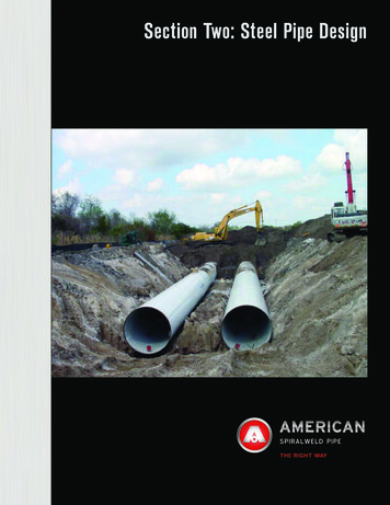
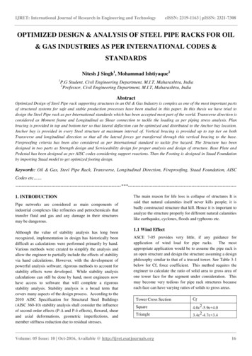
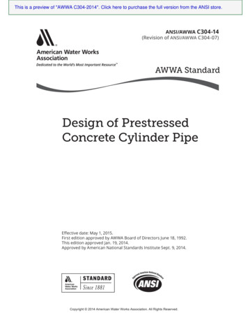
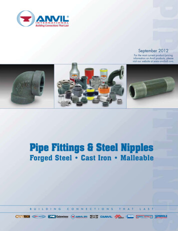
Handbook of PVC Pipe Design and Construction12.6Chapter 12and depth of cover. In some cases, where in-situ lateral soil resistance is negligible suchas in very poor native soils (for example, peat, muck, or highly expansive soils), widetrenches may be more economical than a trench-support system. Under these conditions,a minimum width of embedment material is required to ensure that adequate embedmentstiffness is developed to support the pipe without assistance from the sidewalls. Per ASTMD2321, if the native soil cannot sustain a vertical cut or if it is an embankment situation,the recommended minimum embedment width should be one pipe diameter on both sidesof the pipe. Embedment materials should be Class II granular material or Class I crushedrock. Installation of embedment materials around the pipe should follow ASTM D2321guidelines.In either stable or unstable soil conditions, where wide trench construction is requireda variation of vertical minimum trench width is to lay the pipe in a subditch and backcutor slope the sides of the excavation above the pipe, as shown in Figs. 12.1 and 12.2. Thistype of construction may be permitted where no inconvenience to the public or damage toproperty, buildings, subsurface structures, or pavement will result. In such a case, the widthof the subditch below the top of the pipe should coincide with the values in Table 12.1.12.3.2 Movable Sheeting, Trench Boxes, or ShieldsWhen movable trench support is used, care should be taken to prevent disturbing thepipe location, jointing and embedment. Removal of any trench protection below the topof the pipe and within the dimensions outlined in Table 12.1 for wide trench installationsshould be prohibited after pipe embedment has been compacted. For this reason, movabletrench supports should be used only in wide trench construction, where supports extendbelow the top of the pipe, or on a shelf above the pipe (with the pipe installed in a narrow, vertical-wall subditch). Any voids left in the embedment material as a result of trenchprotection removal should be carefully filled with granular material that is adequatelycompacted. Removal of bracing between sheeting should be done only where backfillingproceeds and where bracing can be removed in a manner that does not relax trench support. When trench boxes or shields are advanced, care should be taken to prevent longitudinal pipe movement or disjointing.In instances where a trench support must extend to the bottom of a ditch, where a subditch is impractical, or where native soils are unstable, a simple alteration to the commonlyused trench box may be the best alternative. A section one-half the length of the box, witha depth of approximately 2 ft cut from the bottom of the box (see Fig. 12.3) will allow thetrench shield to ride on the bottom of a narrow trench, while allowing undisturbed pipeembedment to sit in the back half. As the trench box is moved forward, embedment maybe compacted all the way to the trench wall.Copyright 2012, Industrial Press Inc., New York, NY - http://industrialpress.comCommittee PVC 12.indd 12.620/11/12 10:37 PM
Handbook of PVC Pipe Design and ConstructionPVC Nonpressure Pipe Installation12.7Trench safety is especially important in deep installations.Fig. 12.1 Deep installation.12.3.3 DewateringWhere running or standing water occurs in the trench bottom, or the soil in the trenchbottom displays a “quick” tendency, the water should be removed by pumps and other suitable means such as well points or pervious underdrain bedding to prevent pipe flotation,until the pipe has been installed and the backfill has been placed to a sufficient height.Copyright 2012, Industrial Press Inc., New York, NY - http://industrialpress.comCommittee PVC 12.indd 12.720/11/12 10:37 PM
Handbook of PVC Pipe Design and Construction12.8Chapter 12Examples of SubditchSlope walls toangle of reposeof soilGroundsurfaceGroundsurfaceSubditchtrench widthSubditchtrench widthPipewidthPipewidthPipePipeFig. 12.2 Subditch examples.Cut-away sectionDirectionof travelFig. 12.3 Trench box schematic.Care should be taken that any underdrain is of proper gradation and thickness to preventmigration of material between the underdrain, pipe embedment, and native soils in thetrench below and at the sides of the pipe.12.3.4 Preparation of Trench BottomThe trench bottom should be constructed to provide a firm, stable, and uniform support for the full length of the pipe. Bell holes should be provided at each joint to permitproper joint assembly and alignment. Any part of the trench bottom excavated below gradeshould be backfilled to grade and compacted as required to provide firm foundation. Whenunstable subgrade conditions that will not provide adequate pipe support are encountered,additional trench depth should be excavated and the space refilled with suitable foundation material as specified by the design engineer. In severe conditions, special foundationsmay be required to maintain grade, as specified by the design engineer. A cushion ofCopyright 2012, Industrial Press Inc., New York, NY - http://industrialpress.comCommittee PVC 12.indd 12.820/11/12 10:37 PM
Handbook of PVC Pipe Design and ConstructionPVC Nonpressure Pipe I
18 in. (450 mm) for 4- and 6-in. (100- and 150-mm) pipe sizes No less than 12 to 18 in. (300 to 450 mm) greater than the pipe OD for 8-in. (200-mm) and larger sizes Resulting minimum trench widths are given in Table 12.1. Committee PVC_12.indd 12.4 20/11/12 10:37 PM Handbook of PVC Pipe