Transcription
Direct Strength Method (DSM)Design GuideDESIGN GUIDE CFXX-XJanuary, 2006Committee on Specificationsfor the Design of Cold-FormedSteel Structural MembersAmerican Iron and Steel Institute
PrefaceThe Direct Strength Method is an entirely new design method for cold-formed steel. Adopted in2004 as Appendix 1 to the North American Specification for the Design of Cold-Formed SteelStructural Members, this Guide provides practical and detailed advice on the use of this new andpowerful design method. Features of the Guide includeDesign examples: Extensive design examples, with thorough commentary, covering 14 differentcold-formed steel cross-sections under a variety of different loading and boundary conditions areprovided (Chapter 8). The bulk of the design examples are based on the AISI (2002) ColdFormed Steel Design Manual and allow engineers to make direct comparison between the DirectStrength Method and conventional design.Tutorial: Introductory material to help engineers interpret elastic buckling analysis results, theheart of the Direct Strength Method, is provided (e.g., see Figure 2).Charts: Prescriptive guidelines (Chapter 4) and an example (Section 8.13) for developing beamcharts using the Direct Strength Method are provided. Similar examples are given for columncharts – together they can be used to create span and load tables based on the Direct StrengthMethod.The finer points: Details are not skipped over, for example, extensive discussion on how tohandle unique situations in the elastic buckling analysis of members is provided (Section 3.3).AcknowledgmentsFunding for the development of this Guide was provided to Ben Schafer at Johns HopkinsUniversity by the American Iron and Steel Institute. Members and friends of the American Ironand Steel Institute Committee on Specifications for the Design of Cold-Formed Steel StructuralMembers. provided useful feedback in the development of this Guide. In particular, Helen Chen,Bob Glauz, Perry Green, Dick Kaehler, and Tom Miller provided comments that greatlyimproved the final version.i
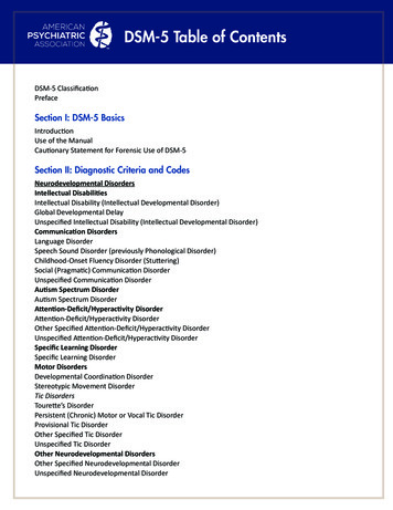
Design Examples Quick Start8.1 C-section with lipsThis lists the six design examplesprovided in Section 8.1. Each designexample uses the same cross-section,in this case, C-section 9CS2.5x059.Reference to AISI (2002) DesignManual examples are also provided.“: ” vs. “ ” ?“: ” in Mathcad this “: ” symbol ishow equations are defined. The righthand side is evaluated and theanswer assigned to the left handside. In this example Mcrl is definedas 0.67My and then evaluated.“ ” in Mathcad the “ ” symbol issimply a print statement. In thisexample Mcrl is defined as 0.67Mywith the “: ” symbol and its value,85 kip-in., is printed to the screenwith the “ ” symbol.Given:a. Steel: F y 55 ksib. Section 9CS2.5x059 as shown to the rightc. Finite strip analysis results (Section 3.2.1)Required:1. Bending capacity for fully braced member2. Bending capacity at L 56.2 in. (AISI 2002 Example II-1)3. Effective moment of inertia4. Compression capacity for a fully braced member5. Compression capacity at a uniform compressive stressof 37.25 ksi (AISI 2002 Example III-1)6. Beam-column design (AISI 2002 Example III-1)8.1-1 Computation of bending capacity for a fully braced member (AISI 2002 Example I-8)Determination of the bending capacity for a fully braced member is equivalent to determining theSpecification. see AISI (2002) example I-8.effective section modulus at yield in the main SpecificationFinite strip analysis of 9CS2.5x059 in pure bending as summarized in Example 3.2.1Inputs from the finite strip analysis include:M y : 126.55 kip inM crl : 0.67 M yM crl 85 kip inM crd : 0.85 M yM crd 108 kip inper DSM 1.2.2, M n is the minimum of M ne , M nl , M nd . For a fully braced member lateral-torsionalbuckling will not occur and thus M ne M y, M nl and M nd must still be checked.M ne : M y(fully braced)M ne 127 kip inLocal buckling check per DSM 1.2.2.2if-then statements“ ” in Mathcad the “ ” symbol is forif-then statements. In this example ifλl 0.776 Mnl is Mne, otherwise if λl 0.776 then the second expressionapplies. The vertical bar shows thepotential choices for Mnl.unitsλl : M neM nl : M ne if λl 0.7760.4 0.4 M crl M crl 1 0.15 M ne if λl 0.776 M ne Mne M nl 94 kip inDistortional buckling check per DSM 1.2.2.3λd : In Mathcad the solution includesunits. Since My is given units of kipin. and Mcrd is defined in terms ofMy, Mnd is also in kip-in. In theprogram units can be changed andthe results will modify accordingly.(subscript "l" " l ")λl 1.22M crlMyM nd : (Eq. 1.2.2-10)λd 1.08M crdM y if λd 0.6730.5 0.5 M crd M crd M y if λd 0.673 1 0.22 M y My “min” in Mathcad the “min”function operates on variables in arow vector, and in this case providesthe member strength Mn.(Eq. 1.2.2-8)(Eq. 1.2.2-9)M nd 93 kip inPredicted bending capacity per 1.3M n : min ( ( M ne M nl M nd ) )minEquationnumbers refer tothe relevant(Eq. 1.2.2-7)parts of DSM(Appendix 1 (Eq. 1.2.2-5)(Eq. 1.2.2-6)AISI 2004)M n 93 kip inThe geometry of this section falls within the "pre-qualified" beams of DSM 1.1.1.2 and thehigher φ and lower Ω of DSM Section 1.2.2 may therefore be used.LRFD:φb : 0.9ASD:Ω b : 1.67φb M n 84 kip inMnΩb 56 kip inDesign examples provided in Chapter 8.ii
Symbols and definitionsUnless explicitly defined herein, variables referred to in this Guide are defined in theSpecification (AISI 2001, 2004) or the Design Manual (AISI 2002).An abbreviated list of variables is provided here for the reader’s convenience.McrlCritical elastic local buckling moment determined in accordancewith Appendix 1 (DSM) Section 1.1.2McrdCritical elastic distortional buckling moment determined in accordancewith Appendix 1 (DSM) Section 1.1.2McreCritical elastic lateral-torsional bucking moment determined in accordancewith Appendix 1 (DSM) Section 1.1.2Mn lNominal flexural strength for local buckling determined in accordancewith Appendix 1 (DSM) Section 1.2.2.2MndNominal flexural strength for distortional buckling determined in accordancewith Appendix 1 (DSM) Section 1.2.2.3MneNominal flexural strength for lateral-torsional buckling determined in accordancewith Appendix 1 (DSM) Section 1.2.2.1MnNominal flexural strength, Mn, is the minimum of Mne, Mnl and MndMyYield moment (SgFy)PcrlCritical elastic local column buckling load determined in accordancewith Appendix 1 (DSM) Section 1.1.2PcrdCritical elastic distortional column buckling load determined in accordancewith Appendix 1 (DSM) Section 1.1.2PcreMinimum of the critical elastic column buckling load in flexural, torsional, or torsionalflexural buckling determined in accordance with Appendix 1 (DSM) Section 1.1.2PnlNominal axial strength for local buckling determined in accordancewith Appendix 1 (DSM) Section 1.2.1.2PndNominal axial strength for distortional buckling determined in accordancewith Appendix 1 (DSM) Section 1.2.1.3PneNominal axial strength for flexural, torsional, or torsional- flexural buckling determinedin accordance with Appendix 1 (DSM) Section 1.2.1.1PnNominal axial strength, Pn, is the minimum of Pne, Pnl and PndPySquash load (AgFy)iii
TermsUnless explicitly defined herein, terms referred to in this Guide are defined in the Specification(AISI 2001, 2004). An abbreviated list of terms is provided here for the reader’s convenience.Elastic buckling value. The load (or moment) at which the equilibrium of the member is neutralbetween two alternative states: the buckled shape and the original deformed shape.Local buckling. Buckling that involves significant distortion of the cross-section, but thisdistortion includes only rotation, not translation, at the internal fold lines (e.g., thecorners) of a member. The half-wavelength of the local buckling mode should be lessthan or equal to the largest dimension of the member under compressive stress.Distortional buckling. Buckling that involves significant distortion of the cross-section, but thisdistortion includes rotation and translation at one or more internal fold lines of a member.The half-wavelength is load and geometry dependent, and falls between local and globalbuckling.Global buckling. Buckling that does not involve distortion of the cross-section, insteadtranslation (flexure) and/or rotation (torsion) of the entire cross-section occurs. Global, or“Euler” buckling modes: flexural, torsional, torsional-flexural for columns, lateraltorsional for beams, occur as the minimum mode at long half-wavelengths.Fully braced. A cross-section that is braced such that global buckling is restrained.Related Definitions from the North American Specificationfor the Design of Cold-Formed Steel Structural Members (AISI 2001)Local Buckling. Buckling of elements only within a section, where the line junctions betweenelements remain straight and angles between elements do not change.Distortional Buckling. A mode of buckling involving change in cross-sectional shape, excludinglocal buckling.Torsional-Flexural Buckling. Buckling mode in which compression members bend and twistsimultaneously without change in cross-sectional shape.Allowable Design Strength. Allowable strength, Rn/Ω, (force, moment, as appropriate), providedby the structural component.Design Strength. Factored resistance, φRn (force, moment, as appropriate), provided by thestructural component.Nominal Strength. The capacity {Rn} of a structure or component to resist effects of loads, asdetermined in accordance with this Specification using specified material strengths anddimensions.Required Allowable Strength. Load effect (force, moment, as appropriate) acting on thestructural component determined by structural analysis from the nominal loads for ASD(using all appropriate load combinations).Required Strength. Load effect (force, moment, as appropriate) acting on the structuralcomponent determined by structural analysis from the factored loads for LRFD (using allappropriate load combinations).iv
Table of Contents1Introduction .11.1Using this Design Guide . 11.2Why use DSM (Appendix 1) instead of the main Specification? . 21.3Designing with DSM (Appendix 1) and the main Specification . 21.3.1Approved usage, Mn and Pn . 31.3.2Pre-qualified members . 41.3.3Rational analysis . 51.4Limitations of DSM: practical and theoretical. 62Elastic buckling: Pcrl, Pcrd, Pcre, Mcrl, Mcrd, Mcre .72.1Local, Distortional, and Global Buckling . 82.2Elastic buckling upperbounds . 92.3Finite strip solutions. 102.3.1CUFSM and other software . 102.3.2Interpreting a solution . 112.3.3Ensuring an accurate solution . 132.3.4Programming classical finite strip analysis. 132.4Finite element solutions . 142.5Generalized Beam Theory . 152.6Manual elastic buckling solutions. 153Member elastic buckling examples by the finite strip method .163.1Construction of finite strip models . 163.2Example cross-sections. 163.2.1C-section with lips . 173.2.2C-section with lips modified . 193.2.3C-section without lips (track section) . 213.2.4C-section without lips (track) modified. 243.2.5Z-section with lips. 263.2.6Z-section with lips modified. 283.2.7Equal leg angle with lips. 303.2.8Equal leg angle. 323.2.9Hat section . 343.2.10Wall panel section. 363.2.11Rack post section . 383.2.12Sigma section . 403.3Overcoming difficulties with elastic buckling determination in FSM. 423.3.1Indistinct local mode. 423.3.2Indistinct distortional mode . 433.3.3Multiple local or distortional modes (stiffeners) . 463.3.4Global modes at short unbraced lengths . 47v
3.3.53.3.63.3.73.3.83.3.93.3.103.3.114Global modes with different bracing conditions. 48Influence of moment gradient. 49Partially restrained modes. 50Boundary conditions for repeated members . 51Members with holes. 52Boundary conditions at the supports not pinned. 53Built-up cross-sections. 54Beam design .564.1Beam design for fully braced beams. 564.2Beam charts, local, distortional, and global buckling as a function of length . 574.3Deflections and serviceability. 594.4Combining DSM and the main Specification for beams . 604.4.1Shear . 604.4.2Combined bending and shear. 604.4.3Web crippling. 604.5Notes on example problems from AISI (2002) Design Manual . 615Column design .625.15.25.36Column design for continuously braced columns. 62Creating column charts . 63Notes on example problems from the 2002 AISI Manual . 65Beam-column design .666.1Main Specification methodology . 666.2Design examples . 676.3Future directions for DSM: Direct analysis of beam-columns . 686.3.1Direct analysis beam-column design strength example. 687Product development .737.17.27.37.48Cross-section optimization. 73Developing span and load tables. 73Rational analysis vs. chapter F testing. 74New pre-qualified members and extending the bounds of a pre-qualified member. 75Design examples .778.1C-section with lips . 788.1.1Flexural strength for a fully braced member (AISI 2002 Example I-8)8.1.2Flexural strength for L 56.2 in. (AISI 2002 Example II-1)8.1.3Effective moment of inertia (AISI 2002 Example I-8)8.1.4Compressive strength for a continuously braced column (AISI 2002 Example I-8)8.1.5Compressive strength at Fn 37.25 ksi (AISI 2002 Example III-1)vi
8.1.6Beam-column design strength (AISI 2002 Example III-1)8.2C-section with lips modified . 898.2.1Flexural strength for a fully braced member8.2.2Compressive strength for a continuously braced column8.2.3Compressive strength at Fn 37.25 ksi8.3C-section without lips (track section) . 938.3.1Flexural strength about strong axis for a fully braced (AISI 2002 Example I-9)8.3.2Flexural strength at Fc 30.93 ksi (AISI 2002 Example II-3)8.3.3Compressive strength for a continuously braced column8.3.4Compressive strength for L 49.3 in.8.3.5Flexural strength about weak-axis (flange tips in compression) for L 49.3 in.8.3.6Beam-column design strength for L 49.3 in., & Pu 2.8 kip & Mu 0.32 kip-in.8.4C-section without lips modified (track section) . 1018.4.1Flexural strength about strong axis for a fully braced member8.4.2Compressive strength for a continuously braced column8.5Z-section with lips. 1038.5.1Flexural strength for a fully braced member8.5.2Flexural strength for L 48.5 in. (AISI 2002 Example II-2)8.5.3Compressive strength for a continuously braced column8.5.4Compressive strength at Fn 25.9 ksi (AISI 2002 Example III-6)8.6Z-section with lips modified. 1098.6.1Flexural strength for a fully braced member8.6.2Compressive strength for a continuously braced column8.6.3Compressive strength at Fn 25.9 ksi8.7Equal leg angle with lips. 1138.7.1Flexural strength about x-axis for a fully braced member8.7.2Flexural strength about minimum principal axis for L 18 in. (AISI 2002 III-4)8.7.3Compressive strength for a continuously braced column8.7.4Compressive strength at Fn 14.7 ksi (AISI 2002 Example III-4)8.7.5Compressive strength considering eccentricity (AISI 2002 Example III-4)8.8Equal leg angle. 1188.8.1Flexural strength for a fully braced member8.8.2Compressive strength for a continuously braced column8.8.3Compressive strength at Fn 12.0 ksi8.9Hat section . 1228.9.1Flexural strength for a fully braced member (AISI 2002 Example II-4)8.9.2Compressive strength for a continuously braced column8.9.3Compressive strength for L 6 ft (AISI 2002 Example III-7)8.9.4Beam-column allowable strength (AISI 2002 Example III-7)8.10 Wall panel section. 1278.10.1Flexural strength for top flange in compressiona. edges free (as in an end panel)b. edges tied (as in a center/repeated panel)8.10.2Flexural strength for bottom flange in compression8.11 Rack post section . 1318.11.1Flexural strength about x-axis for a fully braced membervii
8.11.2Flexural strength about y-axis for a fully braced member8.11.3Compressive strength for a continuously braced column8.12 Sigma section . 1368.12.1Flexural strength for a fully braced member8.12.2Compressive strength for a continuously braced column8.13 Development of a beam chart for the C-section with lips . 1408.14 Development of a column chart for the C-section with lips . 1498.15 Comparison of DSM with main Specification . 1579Manual elastic buckling solutions. 16010 References . 170viii
1 IntroductionThe purpose of this Guide is to provide engineers with practical guidance on the use of the DirectStrength Method (DSM) for the design of cold-formed steel members. The Direct StrengthMethod was adopted as Appendix 1 in the 2004 Supplement to the North American Specificationfor the Design of Cold-Formed Steel Structural Members (AISI 2004). The Direct StrengthMethod is an alternative procedure from the main Specification and does not rely on effectivewidth, nor require iteration, for the determination of member design strength.1.1Using this Design Guide The North American Specification for the Design of ColdFormed Steel Structural Members (AISI 2001)This document, referred to as the Specification, or mainSpecification, forms the basis for design of cold-formed steel. TheDirect Strength Method, which was added to the Specification in2004 as Appendix 1 provides alternative procedures to Chapters Athrough G, and Appendices A through C. Equation numbers in theexample problems (e.g., in Chapter 8) refer to the Specification.2004 Supplement to the North American Specification for theDesign of Cold-Formed Steel Structural Members (AISI 2004)This document is a supplement to the Specification. Part of thissupplement includes Appendix 1, Design of Cold-Formed SteelStructural Members Using Direct Strength Method, which is thesubject of this Guide. The commentary of Appendix 1 isparticularly important for understanding the background of theDirect Strength Method. For use of this Guide Appendix 1 of theSupplement is needed.AISI Manual of Cold-Formed Steel Design (AISI 2002)This Design Manual is not required for using this Guide. However,many of the design examples presented here are based directly onthe examples presented in the Design Manual. The member crosssection designation provided in the Design Manual is used in thedesign examples of this Guide. In addition, much of thecommentary comparing the Direct Strength Method to theSpecification is derived from the examples in the Design Manual.CUFSM (Schafer 2005) Finite Strip SoftwareThis freely available open source software, CUFSM, is utilizedextensively in this Guide for elastic buckling determination of coldformed steel members (www.ce.jhu.edu/bschafer/cufsm). However,CUFSM is not required to utilize this Guide, as (1) closed-formedsolutions are provided for standard shapes, and (2) other softwareincluding CFS (www.rsgsoftware.com) and THIN-WALL(www.civil.usyd.edu.au/case/thinwall.php) are available.1
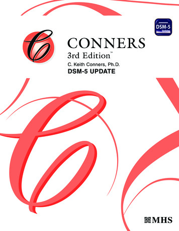
1.2 Why use DSM (Appendix 1) instead of the main Specification?The design of optimized cold-formed steel shapes is oftencompleted more easily with the Direct Strength Methodthan with the main Specification. As Figure 1 indicates,DSM provides a design method for complex shapes thatrequires no more effort than for normal shapes, while themain Specification can be difficult, or even worse, simplyinapplicable. Practical advantages of DSM:(a) conventional shapes no effective width calculations,design effort no iterations required, andmain Specificationmedium uses gross cross-sectional properties.DSM (Appendix 1)mediumElastic buckling analysis performed on the computer (e.g.,by CUFSM) is directly integrated into DSM. This providesa general method of designing cold-formed steel membersand creates the potential for much broader extensions thanthe traditional Specification methods, that rely on closedform solutions with limited applicability. Theoreticaladvantages of the DSM approach: explicit design method for distortional buckling, includes interaction of elements (i.e., equilibrium(b) optimized shapesand compatibility between the flange and web isdesign effortmaintained in the elastic buckling prediction), andmain Specificationhigh or NA*DSM (Appendix 1)medium explores and includes all stability limit states.*NA notapplicableornodesignrulesPhilosophical advantages to the DSM approach:Figure 1 Cold-formed steel shapes encourages cross-section optimization, provides a solid basis for rational analysis extensions, potential for much wider applicability and scope, and engineering focus is on correct determination of elastic buckling behavior,instead of on correct determination of empirical effective widths.Of course, numerous limitations of DSM (as implemented in AISI 2004) exist as well, not theleast of which is that the method has only been formally developed for the determination of axial(Pn) and bending (Mn) strengths to date. A detailed list of limitations is presented and discussedin Section 1.4 of this Guide. Ongoing research and development is endeavoring to address andeliminate current limitations.1.3 Designing with DSM (Appendix 1) and the main SpecificationThe Direct Strength Method is part of the Specification, and was formally adopted as Appendix 1(AISI 2004). The term “main Specification” refers to the Specification excluding Appendix 1.The Direct Strength Method provides alternative predictions for Mn and Pn that may be used inlieu of equations in the main Specification; see Section 1.3.1 and the examples of Chapter 8 inthis Guide. When using Appendix 1 in conjunction with the main Specification reliability ismaintained by the use of the φ and Ω factors given in Appendix 1 as discussed in Section 1.3.2 ofthis Guide. In some situations the Direct Strength Method may form the basis for a rationalanalysis extension to the Specification as discussed in A1.1(b) of the Specification and detailedfurther in Section 1.3.3 of this Guide.2
1.3.1 Approved usage, Mn and PnDSM (Appendix 1 of AISI 2004) provides a strength prediction for Mn and Pn. These nominalflexural (beam) and axial (column) strengths are used in numerous sections of the mainSpecification. Table 1 below provides a roadmap for the replacement of Mn and Pn in the mainSpecification with the predicted values from Appendix 1. This table does not cover the extendeduse of DSM as a rational analysis tool, see Section 1.3.3 of this Guide.Table 1 DSM alternative to main Specification calculationsDSM calculation ÆMnof 1.2.2 in App. 1ÆMn with Mne My*of 1.2.2 in App. 1 ÆMnof 1.2.2 in App. 1ÆMn with Mne My*of 1.2.2 in App. 1ÆPnof 1.2.1 in App. 1ÆPn with Pne Pyof 1.2.1 in App. 1Pnof 1.2.1 in App. 1ÆÆProvides an alternative to the main SpecificationC3.1 Flexural Members – Bending C3.1.1(a): DSM Mn is an alternative to Mn of C3.1.1(a) NominalSection Strength [Resistance] Procedure I C3.1.2: DSM Mn is an alternative to Mn of C3.1.2 LateralTorsional Buckling Strength [Resistance] C3.1.3: DSM Mn is an alternative to SeFy of C3.1.3 BeamsHaving One Flange Through-Fastened to Deck or Sheathing (Rmust still be determined from C3.1.3) C3.1.4: DSM Mn is an alternative to SeFy of C3.1.4 BeamsHaving One Flange Fastened to a Standing Seam Roof System (Rmust still be determined from C3.1.4)C3.3, C3.5, C5.1, C5.2 Combined Bending (interaction equations) C3.3: DSM Mn is an alternative to Mn of C3.3 CombinedBending and Shear C5.1: DSM Mn about x and y axes are alternatives to Mnx and Mnyof C5.1 Combined Tensile Axial Load and Bending C5.2: DSM Mn
cold-formed steel cross-sections under a variety of different loading and boundary conditions are provided (Chapter 8). The bulk of the design examples are based on the AISI (2002) Cold-Formed Steel Design Manual and allow engineers to make direct comparison between the Direct