Transcription
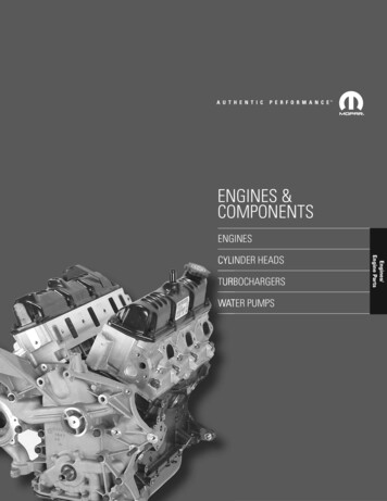
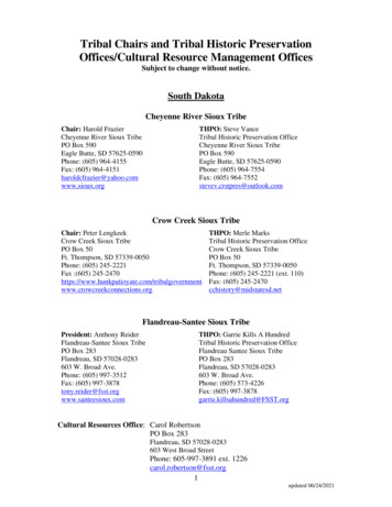
The 964 Turbo engine and engine systemsby Adrian Streather.1991 911 (964) Turbo. Photo: Aldo VanniniThe following information is a brief overview of the 964 Turbo engine and relatedsystems. Hopefully it will provide 964 turbo owners sufficient knowledge tounderstand how these systems operate.964 series Turbocharged enginesThe first turbo type 964-770 was released for model year 1991 and remained thesame for model year 1992. The 964 turbo had the 964 body and chassis structurallystrengthened and given the wide body look. Mechanical systems were upgraded andthe engine installed is an upgraded type 930/68 engine given the designationM30/69. The main differences between the 930/68 and the M30/69 engines are:Crankcase bolts similar tothose used for the normallyaspirated M64 engine.New cylinder design withoptimised thermalcharacteristics.Stainless-steel cylinder headgasket (V2A).930/XX turbocharged engine. Photo: Stephen Kaspar.Full-flow oil filter.Separate belt drive for 115Aalternator/air conditioningcompressor and engine drivenfan.
Continuous injection system (K-Jetronic) with oxygen sensor control with a redesigned fuel distributor assembly.Three-way catalytic converter of metal construction.Optimised turbo-charging system, including a larger intercooler assembly.Boost reduced to 0.7 bar (10.2 psi), down from 0.8bar (11.6 psi) in the 930/68Pressure-controlled transistorised ignition system (air pressure/engine load inputfrom the throttle body to a pressure sensor installed in ignition control unit) withdigital spark control. The ignition system also introduced digital mapping for dwelland timing.In 1993 the 3.3 litre turbocharged engine was replaced with a new 3.6 litre variant.The new engine type M64/50is a turbocharged version of thenormally aspirated M64 engine series.The main differences between theM30/69 and the M64/50 engines are:Crankcase is similar to the normallyaspirated M64 versions.Crankshaft, connecting rods,intermediate shaft and the oil pumpare the same as the M64 series.Cylinder bore 100 mm.Vibration damper on crankshaft.964 Turbo. Photo: Author's collectionStainless steel rings to provide cylinder head sealing.Cylinder heads similar to the normally aspirated M64 version.Exhaust valves are made of “P25” and do not have a sodium filling.Chain drive housing the same as the normally aspirated M64 series.Camshaft and timing changed, exclusive to the M64/50 engine. The camshafts aremade from high-grade chilled cast iron.Oil supply gallery similar to the normally aspirated M64 series. The oil passagesplugged on the normally aspirated M64 series are opened for the M64/50 series.Top valve cover the same as the normally aspirated M64 series.Oil supply line to the turbocharger.Installation of a modified oxygen sensor control unit.Installation of a control pressure regulator with a higher hydraulic pressure at fullload.Installation of a modified throttle body.Installation of a modified and remapped Ignition control unit.Installation of a modified distributor.Note: Both the M30/69 and M64/50 turbocharged engines are designed to operateon 95 RON/ 85 MON fuels. However Porsche recommend that 98 RON fuel is used.Both turbocharged engine variants are not fitted with knock regulation protection.
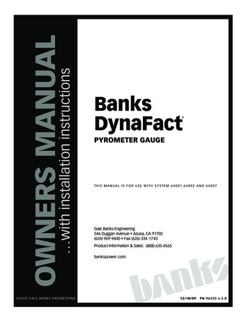
Continuous injection system (CIS, K-Jetronic)(turbocharged models)IntroductionCIS used on the 964 engine is based on previous 911 Turbo systems. US MY1986-89911 Turbo owners will not notice much difference between their 930 turbo engines andthe new M30/69 engine. However owners from the rest of the world (RoW) will noticesome major differences in the Bosch continuous fuel injection systemwith oxygen sensor control and related sub-systems.Basic system operationFuel DistributorThe fuel distributor is madeof aluminium and is fittedwith a capsule valve. Inorder not to retard theover-spring effect duringacceleration, a capsulevalve now replaces thefixed orifice. This capsulevalve opens as soon as thecontrol plunger is liftedduring acceleration. A fixedorifice is used to separatethe lower chamber fromsystem pressure. Pressurein the lower chamber maynow be adjusted by thefrequency valve controllingFuel distributor and air flow sensor assembly.the flow to the return line. The port at the differential pressure valve, i.e. thedifferential pressure and, hence the quantity of fuel injected may be adaptedaccurately according to requirements. The fuel distributor is also fitted with apressure balance valve. The purpose of this valve is to stop a vacuum build up in thecontrol plunger area if the engine is switched off when it is hot. Fuel expands when itis heated up and if there is a build up of vacuum in the control plunger area, when theturbo is next started it may run too rich. The pressure balance valve is used toseparate the volume above the control plunger and the return line. When thesustaining pressure drops below 0.3 bar excess pressure, the pressure balance valveopens to prevent vacuum build up in this area.Note: In the 964 Turbo system the connector at the fuel distributor (sensor platecontact) is no longer used. The fuel pumps are controlled by an engine speed pulsefrom the ignition control unit.
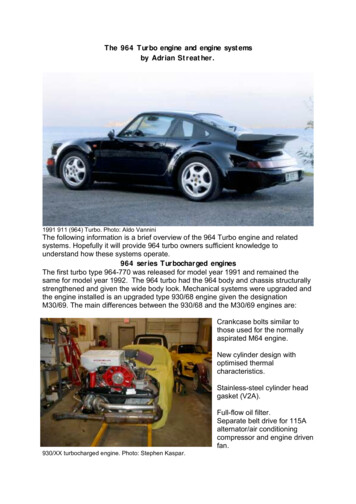
Air flow sensor.Schematic: Dr Ing. h. c. F. Porsche AGWhen the throttle valve opens,the air energy (PL) forces thesensor plate down and the controlplunger is moved upwards. Thefuel above the control plunger liftsthe capsule valve i.e. flow is notdirected past the orifice but isdeviated around the valve. Thisallows the metering port to openfaster to a greater degree. Thepressure pulse inside the lineleading to the control pressureregulator is absorbed by theflexible hose connected betweenthe fuel distributor and controlpressure regulator.Continuous injection without oxygen sensor controlOn 964 turbos fitted with CIS injection without oxygen sensor control, the differentialvalves in the fuel distributor maintain the differential pressure at a constant levelirrespective of the system pressure applied. The injection quantity can therefore onlybe influenced by the cross-section uncovered at the metering unit.The differential pressure between the upper and lower chamber is 0.1 bar. Thediaphragm is only deflected to the extent required by the fuel quantity injected.Continuous injection with oxygen sensor control(964 Turbo theory of operation).In order to adapt the fuel quantity injected to the desired fuel to air ratio at λ 1, thepressure in the lower chambers of the fuel distributor is varied. I.e if the pressure inthe lower chamber is reduced the differential pressure at the metering ports isincreased. This in turn increases the fuel quantity that is injected. In order to vary thepressure inside the lower chambers, those chambers are separated from systempressure by a fixed restriction (as opposed to the standard CIS fuel distributor).Another restriction is provided to connect the lower chambers to the fuel return line.This restriction is of variable design: As long as the restriction remains open,pressure inside the lower chambers can drop. When closed the system pressurebuilds up inside the lower chambers. If this restriction is open and closed at a fastrate (pulsed), the pressure in the lower chamber may be varied according to thepulse-duty factor (ratio of closing time versus opening time). An electromagneticvalve (frequency valve) is used as a variable restriction device. It is controlledelectrically by pulses emitted by the oxygen sensor control unit. The frequency valveis mounted in the fuel return line at the fuel distributor.Frequency valve:The frequency valve is a L-Jetronic pulse fuel injector.The frequency valve is connected to the lower chambers of the fuel distributor and isfitted with a connection leading to the return line.The control units feed square pulses of a constant frequency (approx 70 Hr) but ofvariable pulse width, the frequency valve. This pulse width is referred to as the pulseduty factor.
In lean control means the pulse width or pulse-duty factor is below approximately50%.In rich control means the pulse width or pulse-duty factor is above approximately50%.A constant pulse-duty factor means operation without governing.If a pulse is present at the frequency valve, the needle valve opens to permit fuel flowto the return line. The result of this is that pressure in the lower chamber of the fueldistributor drops until the frequency valve is closed again. As a result of the relativelyhigh frequency of the pulses a medium pressure level is obtained in the lowerchamber.Fuel supplied to the injectors is directly proportional to the pressure in the lowerchamber. The higher the pressure in the lower chamber the less the fuel supplied tothe injectors. The lower the pulse-duty factor, the less the pressure in the lowerchamber is reduced and therefore less fuel is supplied to the injectors. Leanoperation. The more the frequency valve is opened, the lower the pressure in thelower chamber and more fuel is supplied to the fuel injectors. Rich operation.Oxygen sensor control.The oxygen sensor control unit is mounted underneath the left hand seat. There aretwo different part numbers used for the 3.3 litre engine,ROW 965 618 103 00USA 965 618 103 01The Turbo 3.6 system uses a modified oxygen sensor control unit, which processesthe 0 (idle) throttle switch position. This is done to improve pickup of the enginein the low load range. Oxygen sensor speed is only doubled if the throttle openingangle exceeds 7 .Oxygen sensor.The oxygen sensor provides the oxygen sensor control unit with information aboutcombustion efficiency. The oxygen sensor signal is used to continuously vary the airfuel mixture via the frequency valve. The heated zirconia (ZrO2 ) oxygen sensor, fullywarmed up, generates a 0.1 - 0.9 volts fluctuating current in response to oxygencontent in the exhaust gas. Fuel mixture is electronically regulated based on thevoltage output of the sensor. Oxygen sensor out put is unreliable when cold. Theheating element brings the sensor element to operating temperature under normalcircumstances within 90 seconds.
964 Turbo O2 sensor installation. Photo: Kevin RossNote: The O2 sensor in the turbocharged engines is not installed in the catalyticconverter. It is installed in the turbocharger turbine inlet pipe.The oxygen sensor control unit operates in two modes and these are:Open loop mode (up to approximately 90 seconds after first start of the day) is inoperation when the oxygen sensor has not reached normal operating temperature orif the oxygen sensor system has failed. When operating in open loop mode, theoxygen sensor control module supplies a preprogrammed duty cycle to the frequencyvalve.Closed loop mode (activated approximately 90 seconds after the first start of theday) becomes the normal mode of operation once the oxygen sensor has reached atemperature of 315 C (600 F) by being heated by exhaust gases and its own internalheater. The oxygen sensor signal continually modulates the frequency valve toprovide the correct fuel / air ratio.Acceleration enrichmentTo ensure smooth acceleration even when the engine is cold, an accelerationenrichment device operating according to the pulse-duty factor is installed. Theacceleration enrichment process requires the output of the oxygen sensor control unitto be provided to the acceleration enrichment control unit. This control unit is installedalongside the oxygen sensor control unit under the left front seat.The enrichment feature is effective only when the engine oil temperature is less than35 (95 F). As soon as the oxygen sensor temperature switches from cold to hot, anacceleration enrichment at a pulse-duty factor of 75% is available for 0.5 secondswithin 25 seconds. When the engine oil temperature exceeds 35 (95 F) theacceleration enrichment device is controlled for 2minutes after starting the engine toa pulse-duty factor of 75% for 0.5 seconds when the 0 and 7 throttle switches areopen.The acceleration enrichment process is dependent on a number of sensors and otherinputs and these are:35 (95 F) engine oil temperature sensor mounted in the breather housing of thecrankcase.15 (59 F) engine oil temperature sensor mounted in the right hand timing chaincover for the Turbo and in the breather housing of the crankcase for the Turbo 3.6.0 and 7 throttle switches located in the throttle switch body66 or full load throttle switch also installed in the throttle body.
Throttle switch operationWhen the 0 switch opens the pulse-duty factor is increased to 75% for 0.5 seconds.This means the air-fuel mixture is enriched during this period.When the 7 switch opens the air-fuel mixture is enriched again.Note: In the Turbo 3.6 system the enrichment at 0 or 7 is the same. 75% for 0.5seconds.When the 66 or full load switch is closed a signal is supplied to the oxygen sensorcontrol unit and the pulse-duty factor is set at 50%. Full load enrichment isaccomplished by lowering control pressure at the control pressure regulator.Full load enrichment pressures:Turbo: When a boost pressure of 250 mbar is achieved the control pressure (hot) isreduced from 4.5 0.11 bar to 3.2 0.11 bar.Turbo 3.6: When a boost pressure of 250 mbar is achieved the control pressure (hot)is reduced from 4.5 0.10 bar to 2.9 0.15 bar.Control pressure regulator.With the introductionof the 964 Turbo amodified controlpressure regulatorwas also introduced.This new regulatoris fitted with atemperature switchand an altitudecompensator.This regulator isalso know as thewarm up regulator.M30/69 turbocharged engine. Photo: Kevin Ross.Note: The Turbo 3.6 uses a modified version of this regulator, part number 965 606106 00. The hydraulic pressure at full load has been changed for the Turbo 3.6.Operation:The control pressure regulator is fitted with two heating resistors Rv1 and Rv2 thatheat up a bi-metallic spring (1) housed in the control pressure regulator when theengine is running. The bi-metallic spring adjusts control pressure in the fueldistributor via a valve plate. The built in temperature switch (t) is designed to remainopen at temperatures below 15 (59 F). When the switch contacts open, the groundconnection of heating resistor Rv1 goes open circuit. When the engine is startedwhilst ambient temperature at the control pressure regulator is below 15 (59 F),voltage is applied initially only at resistor Rv2; the bi-metallic spring heats up onlyslowly and control pressure builds up gradually. When the ambient temperatureexceeds 15 (59 F), the temperature switch closes to ground. Both resistors Rv1 andRv2 are then connected in parallel. This increases the heating efficiency and heatoutput. As a result the bi-metallic spring heats up faster and the control pressureregulator settles more rapidly.
Turbo control pressures:Initial control pressure at 20 (68 F);2.8 0.15 barOperating control pressure4.5 0.11 barTurbo 3.6 control pressures:Initial control pressure at 20 (68 F);3.0 0.15 barOperating control pressure4.5 0.10 barAltitude compensation:An altitude compensator is built into the new control pressure regulator. Atmosphericpressure acting on the altitude capsule located in the control pressure regulator istaken up at the air cleaner body and is applied to the altitude capsule across theventing line of the control pressure regulator. The altitude capsule acts on the valveplate of the control pressure regulator, thus influencing control pressure.Cold start valve Used to inject additional fuel during a cold start. This is a solenoidvalve installed into the intake plenum.Thermo-Time switch. The purpose of this switch is to control the operation of the coldstart valve. The switch itself consists of a bi-metallic switch which is electricallyheated When the engine is cold or less than 15 (59 F) the bi-metallic contacts in theswitch are closed and when the starter is activated, a ground via these contacts issupplied to the cold valve solenoid which will then close. More fuel is then injectedinto the engine. When the temperature of the bi-metallic strip exceeds 15 (59 F) itopens and removes the ground from the cold start valve and it opens. This is to limitvalve operation and prevent flooding. The valve is only open for a few seconds on acold start. This switch is mounted in the left hand chain housing in the Turbo and inTurbo 3.6 it is mounted in the breather housing of the crankcase .Auxiliary air regulator: To compensate for increased friction inside a cold engine. Thethrottle valve isbypassed by thistemperaturecontrolled regulatorassembly. Again thisregulator useselectrical current towarm a heatingelement and causesthe bimetallic strip tobend gradually,closing the rotaryvalve and cutting offadditional air.M30/69 turbocharged engine. Photo: Kevin Ross
Vacuum limiter valve: During overrun, the engine must be kept from running on anexcessively rich fuel/airmixture. A vacuumcontrolled diaphragm valvehas been installed toprevent this. The vacuumlimiting valve bypasses thethrottle valve and suppliesadditional or auxiliary airrequired to ensure optimumcombustion and not toallow the engine to run toorich.M30/69 turbocharged engine. Photo: Patrik SelestamIntercooler:Installed on top of the throttle housing, is the new and larger intercooler. This newintercooler has an increased cooling surface to improve air intake into the cylinders.The purpose of the intercooler is to increase the density of the air entering the engineintake system. This is achieved by simply cooling the pressurised turbo-charged air.There are number of switches and sensors installed into the intercooler. These are;Boost pressure sensor: This sensor supplies the data to theboost indication system, contained in the trip computer assembly in the tachometer.Boost (measured in bars) is the default display for the Turbo trip computer.Boost pressure switch: This is a pressure safety switch. When turbo boost reaches apreset maximum the switch opens and cuts off power to the fuel pumps. This switchoperates at 1.1 to 1.4 bar. The pulse output is then sent to the turbo control unitwhich removes the earth to the fuel pumps.Temperature sensor: he signal from this sensor is used by the oxygen sensor controlunit to fine-tune the fuel mixture. This sensor is a positive temperature co-efficient(PTC) sensor. This means the resistance increases with an increase in temperature.Re-circulating air valve (also known as the Compressor bypass valve)This valve is designed to stop the turbocharger from operating against a closedthrottle valve. Te re-circulating valve is vacuum controlled and it fitted between theintake and thrust sides of the turbocharger. The re-circulating air valve is locatedbehind the intercooler on the left hand side of the engine.Note: In order to improve valve reliability the original Bosch version is often replacedwith aftermarket versions such as the one manufactured by Forge.
Turbocharged engine controls:Turbo engine management relay and module locationsare listed in the table below.Turbo engine relay and control unit locationsComponent Location964 Turbo relay and fuse panel. Photo: Steve ShanksFuel pump relay(R61) Centralelectric (mainfuse/relay panel)located at the rightrear of the luggagecompartment.Oxygen sensor relay Fuse/relay carrier, left side of the engine compartmentOxygen sensor control unit installed under the left seatAcceleration enrichment control unit installed under the left seatTurbocharger control unit installed under the left seatTurbocharger control unitThe turbo control unit, located under the left seat, controls;2 fuel pumpsSafety cut out circuits of the fuel pumpsBoost pressure safety circuitIgnition delay relayPower supply for1. oxygen sensor control unit which includes switched from open to closed loopoperation.2. acceleration enrichment control unit3. ignition system4. control pressure regulator5. auxiliary air regulator6. frequency valve at the fuel distributor7. oxygen sensor heaterTurbo control unit modes:The program stored in the microprocessor of the turbo control unit covers two modes;Start mode:Is recognised by the microprocessor on the basis of engine speed, i.e. the periodlength of the pulse generator signal. The firing point is triggered at the positive edgeof the pulse generator signal at approximately 15 BTDC.Operating mode:The control unit switches from start to operating mode as soon as the presetthreshold of 630 rpm is exceeded. When engine speed drops below 330 rpm, the idle
firing angle is 0 3 with the throttle switch at 0 (closed) the turbo control unit willswitch from operating to start mode.When the turbo control unit is switched to operating mode it works in conjunction withan operating ignition map stored in the ignition control unit. This combination ofcontrol unit data and ignition control unit data determines the optimum firing point foreach operating condition based on engine load, engine speed, engine temperature,intake air temperature, 0 throttle switch and fuel selector switch position.Ignition delay:In order to ensure complete combustion of the fuel that may have been injectedbefore the engine is turned off. The ignition will remain on for approximately 5seconds after the engine is turned off.964 Turbo engine bay relay panel. Photo: Steve ShanksOther engine sensors and information sourcesFuel selector switch:In certain countries fuel octane levels lower than the recommended RON 95 may bemandated for use in automobiles. In order to avoid random ignition taking place in theengine, the ignition may be retarded by 2.3 from a certain engine load via a 2-pincode plug using jumper part number 944 612 525 01.Manifold pressure sensor:When starting the engine, the manifold pressure sensor is checked for short-circuitingand open circuit, i.e. the firing angle corresponding to the full-load curve (1,800mbar). If output pressure is below 750 mbar it will be short circuit or above 1250 mbarit will be open circuit.Electronic idle stabliserIf the idle speed drops below a certain value a stabilising feature becomes effectiveby moving the firing angle in an “advance” direction.Signal sensorThis sensor is identical to the flywheel speed/reference mark sensor used in thenormally aspirated 964 series of engines. This sensor measures flywheel speed andsupplies its signal to the ignition control unit.Engine temperature sensorA standard negative temperature co-efficient (NTC) sensor that measures the engineoil temperature (engine temperature). It is mounted into the crankcase. This sensor isused to adjust ignition timing in accordance with temperature. The condition of this
sensor is monitored and if it goes open circuit the engine temperature value from thesensor is ignored and a preset value is used.Idle switchThe 0 throttle switch keeps the ignition control unit informed on the idle and overrunmode of the engine.Engine speed governor:To protect the engine from excessive speeds, the turbo control unit interrupts theground pulse to the fuel pump relay at 6,800 rpm, causing the fuel pumps to be deenergised.Fuel DeliveryFuel pumps:The turbo has two fuel pumps. One installed directly behind the fuel tank and theother, in the right hand side of the luggage compartment. Both pumps are controlledby the fuel pump relay R61.Terminal 30 of the fuel pump relay is connected to the positive side of the battery.Voltage is present at terminal 86 when the ignition is switched on. When the engine isstarted, a rpm pulse (equivalent to approximately 30 rpm) is fed from the ignitioncontrol unit to the turbo control unit. This is in turn supplies a ground pulse to therelay coil of terminal 85 of the fuel pump relay. The relay contacts close, causingvoltage to bepresent at the fuelpump fuses and thefuel pumpsrespectively acrossterminal 87. Thiswiring set upprevents the fuelpumps fromoperating when theignition is turned onand the engine isnot running.964 Turbo fuel filter. Photo: Steve ShanksNote: The turbo is fitted with 1 fuel filter and 1 fuel pressure reservoir. The single fuelfilter is connected between the fuel pressure reservoir and the fuel distributor.Fuel injectorsCIS mechanical fuel injectors are precision nozzles. When the fuel system deliversfuel pressure within the normal pressure range, injector nozzles open andcontinuously deliver atomised fuel into the intake ports. Each fuel injector is mountedinto an insert which is screwed into the intake runner. The injector is held inplace by a thick sealing O-ring.Carbon cannister fuel venting system:(also known as the fuel tank breather system):To protect the environment and to reduce specific fuel consumption, all 964s arefitted with a tank breather or carbon cannister system. Fuel vapour is collected in acarbon canister and fed back to the engine if specific requirements are met.
System operation:The fuel vapours are routed from the fuel tank across the expansion tank and therollover safety valve reservoir through the bleeder hose to the carbon canister. Apurge air line ends in the left-hand rear wheel housing. The vent line of the carboncannister is connected to the air filter assembly in the normally aspirated 964s and inthe Turbo. In the Turbo 3.6 system the carbon cannister vent line is fed to the intakeside of the turbocharger across three in-line vacuum controlled valves. These valvesare;Temperature valve which remains open when the engine oil temperature exceeds40 C and provides a vacuum connection between the throttle body (2 bore) and theswitch off valve.Anti-run-on-valve which is triggered by the temperature valve and remains opens atengine oil temperatures above 40 C and with a minimum throttle deflection of 2 andthe engine is not in the boost pressure range.Control valve which is connected directly to the intake manifold below the throttleacross a separate vacuum line. All three valves are connected in series and thecarbon cannister contents can only be drawn off and the air-fuel mixture influencedunder t he following conditions.Engine oil temperature greater than 40 C.Throttle is opened by at least 2 andThe engine is not in the boost pressure rangeIgnition systemThe 964 series of turbocharged engines, the M30/69 and M64/50 use a similar, butnot identical, ignition systems.System components:A single engine driven distributor assembly.One ignition transformerwith built in final driverstage. The ignitiontransformer is mountedabove and to the right ofthe distributor assembly.Six spark plugs.Six spark plug lead set.A Bosch EZ69 electronicignition control unit whichis mounted to the right ofthe engine bay electricaldistribution panel.The Ignition control unit relay(#1) is installed insidethe engine bay electricaldistribution panel.964 Turbo 3.6 engine bay. Photo: Michael BehrmanM30/69 engine:The ignition system of this engine series is based upon the system installed on the930/68 turbocharged engine. Most of the parts used are 930 part numbers except forthe ignition transformer and the ignition control unit.Changes introduced are:
The installation of an electronic ignition control unit with pressure sensor whichprovides pre-programmed dwell angle and timing maps mixed with air pressure orengine load from the throttle body to provide digital spark control. The ignition controlunit part number is 965 602 706 01.Ignition control unit. Photo: Steve ShanksM64/50 engine:Whilst similar to the earlier M30/69 engine ignition system some changes to theM64/50 were introduced the 964 Turbo 3.6 made its appearance in model year 1993.These differences are:The installation of a new ignition control unit with modified ignition mapping preprogrammed into the control unit (part number 965 602 706 02).The pressure sensor line is relocated to the downstream section of the throttlebody. This was done to reduce the impacts of full load pulsations on the pressuresensor installed in the control unit.Distributor modifications:Due to a modification to the cooling fan housing a new distributor assembly with alonger drive shaft is installed.The centrifugal weights (as per the normally aspirated dual ignition system assembly)are installed to ensure overlap between the distributor rotor arm and the individualdistributor cap contacts (each spark plug) at high distributor speeds (large ignitionadvance). These weights help adjust the rotor in the direction of rotation. Helps therotor arm keep up and not lag behind the engine rpm.The installation position of the distributor rotor in firing TDC of cylinder #1 is alsomodified. The notch in the distributor housing is now opposite the fastening nut. Thismodification also caused the spark plug lead positions to be changed.The new distributor part number is 965 602 024 00.The spark plugs used on the M64/50 are type Bosch FR 6 LDC, which are longer lifeand more efficient units with a replacement interval of 40,000 km (25,000 miles).Note: This Bosch spark plug type was installed from model year 1994 in all M64engines, and is approved for retro-fitting to all earlier M64 engine types.
Basic operation of the electronic ignition control unit(Bosch EZ69).(Applicable to all 964 Turbo versions).The control unit receives inputs from:Flywheel speed sensor (pulse generator in the parts catalogue).Fuel octane code.Boost air temperature.0 throttle switch.Power via the relay.The control unit also has a pressure sensor installed. This pressure sensor isconnected to the throttle body. The purpose of the pressure sensor is to provideengine load (amount and pressure of air entering the engine) data to the ignitioncontrol unit.Note: The pressure sensor in the ignition control unit has the same role as the airflow sensor in the normally aspirated engines.The control unit then calculates the correct dwell angle and when to fire each sparkplug based in calculations from all the electronic inputs the pressure input andpre-programmed digital maps.The outputs from the control unit are:Signal at the ignition
US MY1986-89 911 Turbo owners will not notice much difference between their 930 turbo engines and the new M30/69 engine. However owners from the rest of the world (RoW) will notice some major differences in the Bosch continuous fuel injection system with oxygen sensor control and related sub-systems.