Transcription
AAM Ecosystem Aircraft Working Group:Electric Propulsion for Urban Air Mobility
AgendaSeptember 30, 2021TopicSpeakerTime (EDT)Welcome and IntroductionsCarl Russell3:00 - 3:05PMRVLT eVTOL Propulsion overview Peggy Cornell3:05-3:15PMPower Quality research andexperimental capabilityPat Hanlon and Dave Sadey3:15-3:35PMMotor Reliability researchTom Tallerico3:35-3:50 PMWorking group open discussionWrap-up3:50-4:25PMCarl Russell4:25 – 4:30PM
Upcoming MeetingsThe Aircraft Working Group will hold their meeting on the last Thursday ofevery month from 3:00PM -4:30PM EDT (12:00PM -1:30PM PDT). October 28, 2021: November 2021:TBDTBD3
Platform and Discussion Active Participants– Platform: MS Teams– Discussion: MS Teams microphone and chat functions Leave your cameras/webcams off to preserve WiFi bandwidth Enter comments/questions in the chat function on the right side of the screen Use your mute/unmute button Use the “Raise Hand” function in MS Teams to let the emcee know you would like to make acomment or ask a question Say your name and affiliation before you begin speaking Speak loudly and clearly Listen Only Participants– Platform: YouTube Live Stream (go to https://nari.arc.nasa.gov/aam-portal/ for the link!) All Participants– Polling and anonymous questions: Conferences.io Enter https://arc.cnf.io/ into your browser Select the Aircraft Working Group: Electric Propulsion for Urban Air Mobility Questions will be addressed at the facilitator’s discretion4
Revolutionary Vertical Lift Technology (RVLT) OverviewAAM Ecosystem Aircraft Working Group MeetingElectric Propulsion for Urban Air MobilitySept 30, 2021Peggy Cornell, eVTOL Propulsion Subproject Managerwww.nasa.gov5
SummaryNASA RVLT is focused on Vertical lift supporting Urban Air Mobility Three On-going Tech Challengeso Electric propulsion reliability andperformanceo Tools to compute vehicle source noise andperformanceo Fleet noise Approving new Tech Challengeso Ride quality and passenger acceptanceo Crash safetyOur vision is to create a future whereVTOL configurations operate quietly,safely, efficiently, affordably and routinelyas an integral part of everyday life.6
AAM and UAMNASA Focus is on Advanced AirMobility (AAM) Missions– AAM missions characterized by 300nm range– Vehicles require increased automationand are likely electric or hybrid-electric– Rural and urban operations and cargodelivery are included– Urban Air Mobility (UAM) is a subset ofAAM and is the segment that isprojected to have the most economicbenefit and be the most difficult todevelopo UAM requires an advanced urbancapable vehicleo UAM requires an airspace systemto handle high-density /7
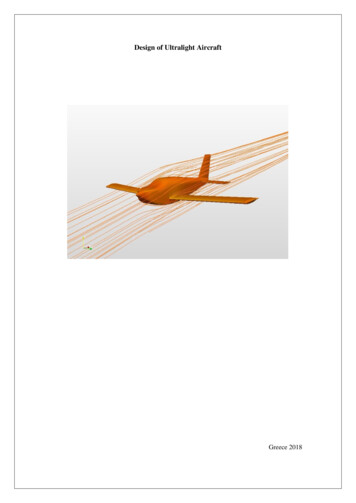
NASA Concept Vehicles – Generic Geometries that Capture Many UAM FeaturesNASA reference vehicles Widely shared Fully documentedcompromises No plans to build or fly these concepts Realistic set ofVehicles contain relevant UAM features andtechnologies––––– Realistic performanceBattery, hybrid, diesel propulsionDistributed electric propulsionHigh efficiency rotorsQuieter rotorsWake interactionsProvide configurations for–––––Communication of NASA’s Urban Air Mobility researchDesign and analysis tool developmentTechnology trade studies and sizing excursionsModeling operational scenariosCommon configurations for studies in acoustics, flightdynamics, propulsion reliability, etc.8
RVLT Near Term Focus for ResearchFY21-FY23VehiclePropulsionReliabilityTech Challenge: Reliable and Efficient Propulsion Components for UAM Re-configure laboratories for electricpropulsion testing Conduct initial single string tests Develop tools to assess motor reliability Develop high reliability conceptualmotor designTech Challenge: UAM Operational Fleet Noise AssessmentUAMFleetNoise Generate Noise Power Distance (NPD) database for several UAMreference configurations and trajectories Conduct fleet noise assessments Initiate psychoacoustic testing to assess human response to UAM vehiclesTech Challenge: Tools to Explore the Noise and Performance of Multi-Rotor UAM VehiclesNoise andPerformanceSafety andAcceptability Plan and conduct validation experiments Improve efficiency and accuracy of conceptual design tools Conduct high-fidelity configuration CFD for validation and reference Improve community transition and training for analysis toolsTargeted Research in These Areas for Future Tech Challenges UAM crashworthiness and occupant protectionAcceptable handling and ride qualities for UAM vehiclesIce accretion and shedding for UAM9
RVLT.TC.UAM.Electric.1Reliable and Efficient Propulsion Components for UAMObjective Develop design and test guidelines, acquire data, and explore newconcepts that improve propulsion system component reliability byseveral orders of magnitude over state-of the-art technology forUAM electric and hybrid-electric VTOL vehicles.E-Drives RigApproach Iterative design, model, test and analyze–––––Apply vehicle level analysisDevelop experimental / analysis capabilitiesConduct tests (reliability of components, tool validation)Provide validated modelsDevelop design guidelines & test proceduresApply Vehicle Level AnalysisDevelop Experimental/ AnalysisCapabilitiesConduct TestsProvide Validated ModelsBenefit/Pay-off Validated power/propulsion/thermal models High reliability motor design – feasibility of 2-4 orders of magnitudereliability improvement Design guidelines for eVTOL propulsion and thermal components Test guidelines for propulsion and thermal components Candidate HVDC Power Quality and Permanent Magnet MachineStandardsDesign Guidelines and TestProcedures10
eVTOL Power / Powertrain Testbeds Scaled Power Electrified Drivetrain (SPEED) -Low-PowerTestbed– Low power (up to 9 kW) motor & controls– Low voltage test platform for high power testbed hardware Advanced Reconfigurable Electrical Aircraft Lab (AREAL) High Power Testbed– Emulated, reconfigurable system (single-string, multi-string)– 1kVDC Peak, nominal 200kW source E-Drives Rig– Test motors, gearboxes & power electronics– Emulation of rotor loads– Mechanical, electrical, vibration, & thermalmeasurementsE-Drives Rig
RVLT Motor Design Efforts – Goal: Improved MotorReliability External Efforts1: 2 Contract Funded Design1)2) 1)2)University of Wisconsin via OSU ULI Integrated, fault-tolerant motor/drive design for RVLTquadcopterBalcones Technologies vis Phase III NASA STTR Developing Brushless Doubly-Fed Machine (BFDM)design for RVLT-class vehicle (100-200 kW)Internal Efforts2:Magnetically Geared Motors and Novel Designs Exploring trade space of reliable motor topologies forUAM applications using in-house codes.Example: Outer Stator Magnetically Geared MotorWinding Reliability Model Development Developing modeling and experimental capability toexplore/predict winding reliability1. J. Swanke, T. Jahns, “Reliability Analysis of a Fault-Tolerant Integrated Modular Motor Drive (IMMD) for an Urban Air Mobility (UAM)Aircraft Using Markov Chains.” 2021 AIAA/IEEE Electric Aircraft Technologies Symposium (EATS).2. T. F. Tallerico, Z. A. Cameron, J. J. Scheidler and H. Hasseeb, "Outer Stator Magnetically-Geared Motors for Electrified Urban Air MobilityVehicles," 2020 AIAA/IEEE Electric Aircraft Technologies Symposium (EATS), New Orleans, LA, USA, 2020, pp. 1-25.
Standards & Tools Leading two SAE standards– AS7499 - Aircraft High Voltage Power Quality Standard (D. Sadey)– AS8441 – Minimum Performance Standard for Permanent Magnet Propulsion Motors and Associated Drives(Pat Hanlon) Participate in AAM (UAM) Aircraft Design& Development Working Group Developing Analysis Tools:– NPSS Developed high level electrical power system models & electrical port for architecture trades Demonstrated electrified propulsion system models Accepted into next release of NPSS– EPS-SAT Electrical power system sizing Utilized for trade studies and sensitivity analyses– Toolset for Motor Reliability Reliability Modeling of Electric Motor
14
RVLT Experimental Capabilities and PowerQuality InvestigationPat Hanlon & Dave SadeyNASA GRC
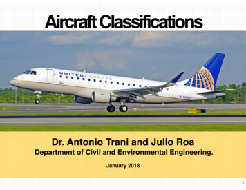
RVLT E-Drives Rig (POC: Justin Scheidler/GRC)ScopeMotor(input)Dynamometer(output) Test motors, gearboxes, & power electronics Mechanical, electrical, vibration, & thermal measurements After upgrades completed, capable up to 21,500 rpm input& 7,400 rpm outputKey capabilities for this tech challengeE-Drives Rig (pre-upgrades) Validation-quality data (very high precision – e.g., gearboxefficiency up to 0.2% with 95% confidence) Directly measure temperature of energized motor windings (up to 1000 V RMScontinuous) Emulate rotor loads with new generator dynamometer Year-round operation (no reliance on cooling tower water) Provides platform for magnetic gear and motor evaluationSpecific Experiments Motor efficiency, output torque, and temperatures under steady-stateand transient conditions Performance mapping of magnetic gears (& possibly magnetically-gearedmotors) for motor design code validation & TRL advancement of new conceptsNew Generator
RVLT E-Drives Rig CapabilitiesGenerator capability overlaid with eVTOLmotor operating points (known orapproximated)Generator capabilities: Controlled via 500 Hz control loop Continuous– 0-2400 rpm238 Nm– 2400-3840 rpm 60kW constant– 3840-7400 rpm decreasing power to31kWat 7400 rpm Short duration (60 seconds)– 160% overload
RVLT Scaled Power ElectrifiEd Drivetrain (SPEED) Capabilities– Low power (up to 9 kW) motor & controls– Low voltage test platform for high power testbedhardware– Allows team to investigate controls and startvalidation/refinement of tools (NPSS andMATLAB)– Single-string (source-load) analysis Status– Assembly complete– Initial integrated motor/inverter tests andcharacterization begun– Integration and EMI lessons learned will be ofbenefit to AREAL
RVLT Advanced Reconfigurable Electrified Aircraft Lab (AREAL) Overview Scope– Investigate Power Quality & Integration Issues– Feed Standards (AS7499, AS8441) Capabilities– Emulated, Reconfigurable System Single-string, Multi-String– 1kVdc Peak, 600-700Vdc Nominal– 200kW Nominal Source Capacity– Ability to test Faults Experiments– Nominal, Transient, Fault Operation– Characterization and Response
AREAL Hardware DC Emulators– Reconfigurable to emulate most DC sourcesfrom a small-signal and transient level Physical Motor Stand– State-of-the-Art Inverter/Motor, Back-to-Back– Can replace as needed Motor Emulator– Ability to Emulate Physical Motor– Ability to Introduce Faults Fault Protection– Initially Contactors/Fuses– In the process of procuring advanced fault protection devices
AREAL DC Emulator Capabilities High Bandwidth DC Power Supply– 20kHz Large Signal Bandwidth– 40kHz Small Signal Bandwidth 500V, 100kW Bidirectional (2Q) per unit Multiple Applications– Source Emulator– Power Sink– Limited Capability as Amplifier for ImpedanceSweeps– Constant Power Load with programmablebandwidth Currently Developing Modifications– Developed dynamic model of 650V Wound FieldGeneratorunder Phase III SBIR with PCKA for PQ Study– Generator Model meets Lift Cruise PowerSystem PQ Requirements in accordance withAS7499 HVDC Power Quality– Using DCE dynamic model from WPAFB to matchtransient and frequency response of generatorwith mods– Also investigating low cost/ quick turnaroundemulation strategy w/ Speedgoat
AREAL StatusAREAL Testbed Lab layout being finalized Facility 480V Power Complete Cooling System being upgraded Arc Flash Study Completed forSingle String Safety Permit being updated
DC Power Quality What is Power Quality and why does it matter? Physical description of power, namely voltage (DC) Applicable during any operational period (Normal, Abnormal, Emergency) Voltage: Steady-state, transient, ripple Stability, fault conditions, & much more Improves reliability Reduces component failures by defining operational boundaries Ensures stable operation Defines/drives proper fault recovery Drives one towards ‘plug and play’ approach to design and integration Not completely obtainable, but moves one closer Helps guide lower level standards (e.g. components, connectors, etc.)
RVLT Example Study – Model Overview Work done via contract with PCKA Lift-Plus-Cruise Vehicle Model (Conceptual NASA Design) 650V, 1MW Simulink Power System Model for PQ Studies Generator, one cruise motor, four lift motors, and a powerdistribution unit (PDU) for each bus, with two busses total. Each generator and motor has an integral rectifier andinverter and are scaled based on validated models Utilizes directional overcurrent protection scheme
Power Quality Analysis Overview System iteratively designed and tuned to meet aninternal PQS specification Normal Operation Steady-State, Transient Voltage Stability Abnormal Operation Voltage response under short circuit conditions
Steady State Voltage Requirement: Steady-State Voltage must remain between 0.93-1.04 p.u. at UE Terminals Covers No-Load to Full-Load 604.5 to 676 Vdc at UE Terminals No Load Voltage of 650Vdc Full Load Voltage 649.1Vdc
Load Step Transient Voltage Requirement: EPS Transient Voltage must remain within thedefined window limits under 50% load steps Resistive Loads stepped 10 to 60%, 60 to 10%, 45 to 95%,and 95 to 45% at UE Terminal Locations Worst-case voltage response was at Cruise Motor Terminals Spikes 10usec ignored
Small Signal Stability Requirement: Ratio of Source to Load Impedance from 30Hz to100kHz shall remain within the 60 degree, 3dB bounds shown Required modifying controller gains & input/output filters Stayed within the required bounds for all loads & at main bus Zs/Zl at Cruise Motor Terminals Zs/Zl at Lift Motor 8 Terminals
Small Signal Stability (cont.) Source and Load Complex Impedance PlotsCruise MotorLift Motor 8
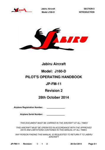
Abnormal Voltage Response Requirement: EPS Transient Voltage must stay within the over- andunder-voltage limits shown in event of a fault Introduced short circuit faults onto Lift Motor branch circuits Observed lift motor terminal voltages on unfaulted branchcircuits Spikes 10usec ignored
Abnormal Voltage Response (cont.)679Vdc384Vdc31Lift Motor 4 UE Terminal VoltageFault Initiated/Cleared on Branch Circuit 8Lift Motor 8 UE Terminal VoltageFault Initiated/Cleared on Branch Circuit 4
Conclusion and Future Work Designed and Tuned 650Vdc, 1MW UAM Power SystemMet Internal PQS RequirementsNormal and Abnormal Response Data to provide point design forstandards developmentFuture Work Currently analyzing soft faults (may require updates and re-evaluation)De-tuning filters to analyze marginal stabilityAnalyze different fault strategies / responsesIntroduce cross-tie and analyze bus recovery & other PQ metrics
33
National Aeronautics and Space AdministrationRVLT Motor Reliability ResearchThomas TallericoNASA Glenn Research CenterThis material is a work of the U.S. Government and is not subject to copyrightprotection in the United States.www.nasa.govNational Aeronautics and Space AdministrationAAM Working Group Meeting 9/30/21Urban Air Mobility Electric Motor Reliability34
Winding Reliability White Paper Expectto publish in next couplemonths Currentlycollecting feedbackfrom SME’s Copyavailable on requestNational Aeronautics and Space AdministrationUrban Air Mobility Electric Motor Reliability35
Summary of 2019 RVLT-sponsored FMECA Study Likely that the propulsion system would need to have 10-10 failure rates per flight hour, or less, in orderto meet the EASA SCVTOL- 01 air vehicle requirement of 10-9 catastrophic failures per flight hour36National Aeronautics and Space AdministrationUrban Air Mobility Electric Motor Reliability36
Motivation and Study GoalsRVLT Technical ChallengeBecause there is a lack of data for propulsion systems and thermal management systems forUAM vehicles, NASA will develop design and test guidelines, acquire data, and explore new conceptsthat improve propulsion system component reliability, culminating by demonstrating 2-4 orders ofmagnitude improvement in 100kW-class electric motor reliability.National Aeronautics and Space AdministrationUrban Air Mobility Electric Motor Reliability37
VTOL Electric Motor Unit Reliability AssessmentFramework for Failure Mode Prioritization & Reliability PredictionVTOL Electric Motor ReliabilityMotor Subcomponents& Key Failure Modes Prioritized Motor Windings/Coils1. Degraded insulation2. Voltage / Current Overloading3. Short circuitStatistical Combination of Sub-Component ReliabilitiesMotor Bearings1. Improper, dirty, or degradedlubrication2. Overloading3. Corrosion4. VibrationMotor Magnets1. Demagnetization2. Brittle fractureMotor Heat Extraction1. Reduced heat transfer rate2. Loss of flow3. OverheatingResearch Required to Improve Reliability forVTOLCritical Reliability Parameter Needs Refinementand Engineering Guidelines for VTOLImportant Reliability Parameter with AvailableEngineering Solutions for VTOLRotor & Structure1. Fatigue failure1.Insulation Material /Grade2.Temperature (Mean &Peak)1.Bearing DN & SurfaceSpeed2.Materials1.Temperature2.Magnetic Loading1.Thermal Cycles2.Heat Transfer1.Low Cycle Fatigue2.High Cycle Fatigue3.Thermal Expansion4.Electrical Stress3.Lubrication4.Alignment & DimensionalPrecision3.Current Transients4.Shock & Vibration3.Materials4.Temperature Distribution3.Gyroscopic Loads(maneuver)4.Vibration5.Vibration, Fretting7. Cleanliness /Environment (humidity,debris, )5.Gyroscopic Loads(maneuver)6.Rotor Lift & MomentLoads5.Coolant Temperature6.Coolant 8.Alternate BearingTechnologies7.Altitude Effects8.Cleanliness / Debris7.Thermal Cycling8.Manufacturing Quality9.Bearing ArcingNational Aeronautics and Space Administration9.CorrosionFailure Modes &Reliability Influencing Parameters & Variables Prioritized Urban Air Mobility Electric Motor Reliability38
Motor Winding Insulation StressesElectricalThermochemicalNational Aeronautics and Space AdministrationMechanicalContaminationUrban Air Mobility Electric Motor Reliability39
Electrical Stress DrivesFinal Failure InstantaneousBreakdownUnlikely ElectricalAging-Repetitive Partial DischargesCreating Electrical TreesThrough InsulationNational Aeronautics and Space AdministrationUrban Air Mobility Electric Motor Reliability40
Electrical Aging in UAM Motors Onset of Electrical aging End of life Voltage source inverter fed f 20 -100 kHz Small voltage rise timeType 1 (Organic Insulation) Polymers (Polyimide - Polyethylene) Higher Design Electrical Field than Type 2 (Inorganic) Very susceptible to damage in presence of PDhttps://ieeexplore.ieee.org/document/6232601IEC 60034-18-41 – relevant standardMonitoring for PD important but difficult in inverter fed systems[1] 3-parts: https://ieeexplore.ieee.org/document/9350653[2] al Aeronautics and Space AdministrationUrban Air Mobility Electric Motor Reliability41
Thermal Chemical Aging Chemicaldegradation ofinsulation at set temperature Oxidationmost common ASTM D2307 (Magnet wirethermal classification) Causes insulation to shrink andincrease capacitance [3] Insulation becomes more brittleand more susceptible tomechanical stresses [2]National Aeronautics and Space Administration[1] 464[2] https://ieeexplore.ieee.org/document/8088680[3] 657Urban Air Mobility Electric Motor Reliability42
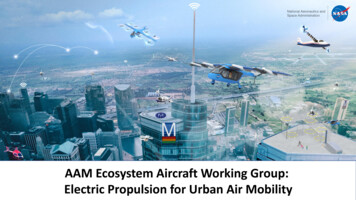
UAM Motor Design for Thermochemical Agingpublished at EATs 2021 MotorDesign for UAM missionsconstrained by thermochemicalaging AssumingClass 220 Cinsulation Target10,000 MissionsMultirotor Vehicle Motor Thermal Profiles270Winding Hot Spot Temperature Paper25023021019017015013011090700500100050kW D11500 2000 2500Mission Time(s)100 kW D130003500100 kW onal Aeronautics and Space AdministrationUrban Air Mobility Electric Motor Reliability43
Mechanical Aging MechanicalFatigue Thermo-Mechanicalis dominantElectromagnetic forces are weak Leaststudied stressOnly matters for starts and stops Likelymost important for UAMStarts and stops every 20 minNational Aeronautics and Space AdministrationUrban Air Mobility Electric Motor Reliability44
Coil Mechanical Stress Studies ExampleDesigns Exploredfor Mechanical Stress due toThermal Mission Profile CoilMechanical Stress likelymore limiting thanthermochemical aging forUAM motor designNational Aeronautics and Space AdministrationUrban Air Mobility Electric Motor Reliability45
Problems for UAM Motor Winding Design Data for PDIV as a function of mechanicaland thermal aging doesn’t exits in openliterature Most Standards specify comparativeaccelerated aging to qualify/certify windings Requires reference system that hasknown life in target operating condition IEC-60034 and IEEE 117 Reference motors/systems for UAM Accelerated thermo-mechanicalaging not possibleNational Aeronautics and Space AdministrationUrban Air Mobility Electric Motor Reliability46
NASA Plan Forward Developfundamental insulationsystem test method CollectPDIV as function ofcombined thermochemical andmechanical agingNational Aeronautics and Space AdministrationUrban Air Mobility Electric Motor Reliability47
NASA Plan Forward ContinuedNational Aeronautics and Space AdministrationUrban Air Mobility Electric Motor Reliability48
49
Upcoming MeetingsThe Aircraft Working Group will hold their meeting on the last Thursday ofevery month from 3:00PM -4:30PM EDT (12:00PM -1:30PM PDT). October 28, 2021: November 2021:TBDTBD50
Aircraft Working Group Point of Contacts Coordinator: BreeAnn Stallsmith (breeann.m.stallsmith@nasa.gov) Technical POC: Carl Russell (carl.r.russell@nasa.gov)Comments, suggestions for future topics, and other workgroupinformation: Visit the website: https://nari.arc.nasa.gov/aam-portal/ ; or Email us at: arc-cal-nari@mail.nasa.govSee you at the next meeting on October 28, 2021!51
RVLT.TC.UAM.Electric.1 Reliable and Efficient Propulsion Components for UAM E-Drives Rig Objective Develop design and test guidelines, acquire data, and explore new concepts that improve propulsion system component reliability by several orders of magnitude over state-of the-art technology for UAM electric and hybrid-electric VTOL vehicles .