Transcription
Acoustic Virtual Vortices with Tuneable Orbital AngularMomentum for Trapping of Mie ParticlesAsier Marzo1*, Mihai Caleap1*, Bruce W. Drinkwater11Faculty of Engineering, University of Bristol. University Walk, Bristol BS8 1TR. UK.*Correspondence and requests for materials should be addressed to Asier Marzo, amarzo@hotmail.com orMihai Caleap mihai.caleap@bristol.ac.uk. Office 1.1 Queen's Building, University Walk, Clifton BS8 1TR,Bristol, United Kingdom. 44 (0) 117 331 5919Materials and MethodsNumerical simulationsIncident acoustic fieldConsider a fluid with ambient density 𝜌 and speed of sound 𝑐 𝜔/𝑘, where 𝜔 is the angularfrequency and 𝑘 is the wavenumber. The incident pressure field generated by our multi-elementarrays was calculated assuming that the normal component of the vibrating velocity 𝑉0 is constantalong the surface of each element (i.e. piston source model). In such a case, the solution for thecomplex amplitude of acoustic pressure for a flat circular piston at the far field, is well known [53].The overall pressure field of the array in the far field at observation point 𝒓 can be calculated bysumming the pressure contribution from each element,𝑝𝑖𝑛 (𝒓) 𝑝0 𝐷(𝜃𝑗 )𝑗ei𝑘𝑟𝑗𝑟𝑗ei𝜙𝑗 ,(1)where 𝑝0 𝜌𝑐𝑉𝑜 is a constant that defines characteristic pressure amplitude at the radiating pistonsurface, and 𝐷(𝜃𝑗 ) 2𝐽1 (𝑘𝑏 sin 𝜃𝑗 )/(𝑘𝑏 sin 𝜃𝑗 ) is a directivity function that depends on the angle𝜃𝑗 between the element axis and 𝒓. Here, 𝐽1 is a first order Bessel function of the first kind, 𝑏 is theradius of each piston, (𝑟𝑗 , 𝜃𝑗 ) are the local polar coordinates. 𝑟𝑗 is the distance from 𝒓 to the transducerand 𝜙𝑗 is its phase.To generate a vortex of topological charge ℓ focused at 𝒓𝒇 the phase of each transducer is set suchthat 𝜙𝑗 ℓ𝜑𝑗 𝑘𝑑𝑗 , where 𝑑𝑗 is the distance between the element centre and 𝒓𝒇 , and 𝜑𝑗 is theazimuthal angle between the centre of the array and the element axis. The change of chirality arrivessimultaneously at the particle only if the distances between the transducers and the particle are equal.If the particle-transducer distances were not equal, a per-transducer delay in the switching of thechirality should be introduced.1
Scattered FieldThe linearity of the problem allows us to represent the scattered field 𝑝𝑠𝑐 as a series of sphericalharmonics 𝑌𝑛𝑚 (Ω) (where Ω (𝜃, 𝜑) is the solid angle in spherical coordinates): 𝑛(1)𝑚𝑝𝑠𝑐 (𝒓) 𝑝0 ℎ𝑛 (𝑘𝑟)𝑇𝑛𝑚 𝐴𝑚𝑛 𝑌𝑛 (Ω).(2)𝑛 0 𝑚 𝑛(1)Where (ℎ𝑛 ) is a spherical Bessel (Hankel) function, 𝑇𝑛𝑚 is the scattering coefficient, and 𝐴𝑚𝑛 arethe expansion coefficients from the incident field, often called beam-shape coefficients.The scattering coefficient 𝑇𝑛𝑚 characterises the properties of the scattering particle: it depends onthe particle shape, boundary conditions, internal properties and on the frequency, but not on theincident field. For a rigid sphere of radius 𝑎 [54], the scattering coefficient is given by 𝑇𝑛𝑚 ′(1) 𝑗𝑛′ (𝑘𝑎)/ℎ𝑛 (𝑘𝑎)𝛿𝑛𝑚 , where the prime symbol denotes differentiation and 𝛿𝑛𝑚 is Kronecker’sdelta.The expansion coefficients 𝐴𝑚𝑛 can be obtained from the incident field using the orthogonality1 Ω 𝑝𝑖𝑛 (𝑅, Ω) 𝑌𝑛𝑚 (Ω)dΩ(𝑘𝑅)𝑛property of the spherical harmonics as 𝑝0 𝐴𝑚𝑛 𝑗, where 𝑅 is theradius of the spherical region in which the incident field 𝑝𝑖𝑛 of Eq. (1) propagates; this regioncontains the spherical object.Radiation force and torqueRadiation force and torque appear because of a change in wave momentum due to scattering at anobstacle. A perfect sphere would not be subjected to any torque, in this case the torque appears dueto absorption from the fluid surrounding the particle, the particle itself or small irregularities on itssurface. By integrating the rate of linear (angular) momentum change, averaged over the waveperiod, projected onto the objects’ surface normal 𝒏 over a mathematical surface 𝑆 enclosing thesystem, we obtain the radiation force (torque) acting on the system,𝓕𝓟( ) () 𝒏 d𝑆,𝓣 𝑟𝑎𝑑𝒓 𝓟𝑆(3)where the time-averaged momentum flux [55] is given by:1𝓟 (4𝜌〈‖𝒗‖2 〉 〈‖𝑝‖2 〉11) 𝐈 2𝜌〈Re(𝒗 𝒗)〉4𝜌𝑐 2(4)Here, ‖𝑝‖2 𝑝𝑝 , ‖𝒗‖2 𝒗 𝒗, with 𝑝 and 𝒗 denoting the complex pressure and particle velocitydue to an acoustic field with time dependence exp( i𝜔𝑡), 𝐈 is a 3x3-unit matrix, Re indicates thereal part, means complex conjugation, 〈 〉 means the time average, and 𝜔 represents the angular2
velocity. Note that the total fields are incident plus scattered fields 𝑝 𝑝𝑖𝑛 𝑝𝑠𝑐 and 𝒗 𝒗𝑖𝑛 𝒗𝑠𝑐 . The fluid particle velocities can be obtained from the pressure field as 𝒗 𝑝/(i𝜔𝜌).Particle dynamicsWhen a spherical particle is placed in an acoustic vortex trap, it experiences radiation forces thataffect its translational motion, dependent on the combined action of gravity, and the fluid drag force,its size and the acoustic properties of the host and particle media. An additional lift force appears ifthe particle rotates – the lift force is the Magnus force. The translational motion of the particle withsimultaneous rotation in a fluid is characterized by two dimensionless parameters: Reynolds numberℛ 2𝑎‖𝒖‖/𝜂 and particle spin number (or dimensionless angular velocity) 𝛾 𝑎‖𝝎‖/‖𝒖‖. Bothℛ and 𝛾-numbers are based on the relative velocity of the particle with respect to the backgroundfluid. In our case, the fluid is assumed to be at rest, thus 𝒖 𝒓̇ denotes the translational particlevelocity, 𝒓 is the position of the particle, and 𝛀 is the angular velocity of the particle rotation aboutits centre of mass.The mutual effect of translational and rotational movements is described by the following system ofequations,𝓂𝒂 𝓂𝒈 𝓕𝑑𝑟𝑎𝑔 𝓕𝑀𝑎𝑔 𝓕𝑟𝑎𝑑 ,(5)ℐ𝜶 𝓣𝑑𝑟𝑎𝑔 𝓣𝑟𝑎𝑑 ,(6)where 𝓂 is the mass of the sphere, and ℐ (2/5)𝓂𝑎3 is its moment of inertia. Here, 𝒂 𝒓̈ denotesthe particle translational acceleration, 𝜶 𝛀̇ its angular acceleration, and 𝒈 is the gravitationalacceleration. The fluid forces acting on the sphere are given by𝜋𝓕𝑑𝑟𝑎𝑔 2 𝑎2 𝜌𝐶𝐷 𝒖‖𝒖‖,𝜋𝓕𝑀𝑎𝑔 2 𝑎2 𝜌𝐶𝑀 𝒖‖𝒖‖,(7)(8)where 𝐶𝐷 and 𝐶𝑀 are the dimensionless drag and Magnus force coefficients. For low Reynoldsnumber, 𝐶𝐷 24/ℛ (Stokes [56]) and 𝐶𝑀 2𝛾 (Rubinow and Keller [57]) leading to 𝓕𝑑𝑟𝑎𝑔 6𝜋𝑎𝜂𝜌𝒖 and 𝓕𝑀𝑎𝑔 𝜋𝑎3 𝜌𝒖 𝛀. The latter equation reflects directly the dependence of theMagnus force not only on the translational velocity 𝒖 but also on the angular velocity 𝛀. The particlerotation velocity is limited by the torque 𝓣𝑑𝑟𝑎𝑔 due to the viscous shear stresses on the particlesurface. This torque can be calculated for a spherical particle by the formula𝓣𝑑𝑟𝑎𝑔 𝜋𝑎3 𝜌𝐶𝛾 𝒖‖𝒖‖,(9)where 𝐶𝛾 is the dimensionless drag torque coefficient. For small Reynolds numbers, Kirchhoffobtained [58] 𝐶𝛾 16𝛾/ℛ, leading to 𝓣𝑑𝑟𝑎𝑔 8𝜋𝑎3 𝜂𝜌𝛀. However, given an observed3
translational particle velocity in the radial direction on the order of 0.4 m/s for a larger particle ofdiameter 5 mm, the Reynolds number for the flow around the particle is on the order of 200. Hence,the simple small Reynolds number relations for the fluid forces and the torque cannot be used. Forthese intermediate to high Reynolds numbers we employ the Brown-Lawler model [59] for 𝐶𝐷 ,Oesterle-Dinh model [60] for 𝐶𝑀 , and Lukerchenko et al. model [61] for 𝐶𝛾 , which were shown toyield good agreement with experimental data,0.407ℛ(1 0.15ℛ 0.681 ) ℛ 8710ℛ𝐶𝐷 24, ℛ 2 105 ,ℛ𝐶𝑀 0.45 (2𝛾 0.45)e 0.075𝛾0.4 ℛ 0.7, 10 ℛ 140, 1 𝛾 6,𝐶𝛾 𝐶𝛾0 (1 0.0044ℛ0.5 ), 2 103 ℛ 2 104 , 0.2 𝛾 2,(10)(11)(12)where 𝐶𝛾0 is calculated using the data from Sawatski et al. [62].The remaining radiation force and torque factors in Eqs. (5) and (6) are calculated using Eq. (3). Weneglect the effects of acoustic streaming. In our case, the penetration of the viscous wave is less than11μm (40kHz wave in air at 25C) which is small compared to the radius of the employed particles(i.e. larger than 500μm), making the effects of streaming force not significant [63,64]. We alsoneglected the acoustic rotational streaming, agreements between experiments and simulation supportthis approximation. In water, the torque drag was reduced by a maximum of 10% due to this effect[7]; due to the lower viscosity of air, the streaming-induced-torque effect could be expected to beweaker in our case. The only experiment of OAM transfer in air [11] did not assume or considerstreaming effects. Furthermore, it is reasonable to assume that acoustic rotational streaming isreduced by the rapid change in direction of the vortices.We have computed the solution of the dynamics problem of a spherical particle under its own weight,encompassing viscous drag, the Magnus effect, and acoustic radiation forces and torques. The timedependent system (5) and (6) was solved using a simple Euler integration method by providing aninitial position (𝑥0 , 𝑦0 , 𝑧0 ) for the particle. At each time step, the acoustic radiation forces andtorques are recalculated for the new position. Single particles were placed inside the vortex trapinitially located at (0.5, 0, 0) mm; different initial positions within the trap did not affect the resultspresented in the main text (Figure S10). The dynamics were simulated for 2 s with a time step of 0.1ms. The particle was considered ejected when its distance from the centre of the trap was greaterthan the radius of the high intensity central ring.Time constant for rotational dynamicsThe radiation torque, moment of inertia of the particle and the viscosity of air govern the rotationaltime constant. In response to this torque, an absorbing spherical particle develops an angularacceleration with respect to its centre. A simple order of magnitude for the time constant can be4
obtained by using the Kirchhoff approximation for the drag torque. Integrating Eq. (6) with the initialcondition 𝛀(𝑡 0) 0 yields,𝛀 𝛀𝑐𝑡 (1 e 𝑡/𝜏 ),(13)where 𝛀𝑐𝑡 𝓣𝑟𝑎𝑑 /(8𝜋𝑎3 𝜂𝜌) is the steady, or terminal, angular velocity, and 𝜏 ℐ/(8𝜋𝑎3 𝜂𝜌) isthe time constant of the accelerated particle rotation. For particles with diameters ranging between1 and 5 mm, 𝜏 varies between 25 ms and 0.5 s, and is proportional to 𝑎2 . We note that our switchingrate is significantly faster than this time constant, meaning that the particle in a 𝒱𝒱 tends to rotateat a near steady speed rather than oscillating between the two component 𝑅𝒱 states. If the particleis in the centre of the vortex and does not orbit around, the torque can be directly obtained using theformulation from Zhang et al. [8].Limits on switching rateThe switching rate 𝑓𝑅 for a virtual vortex depends on the dynamics of the system, which in turndepend on the particle size. If the switching rate is too slow, i.e. 𝑓𝑅 1/𝜏, then a particle oscillatesbetween the two states. For example, under these conditions the particle may be ejected again orrotate alternately in one direction and then the other. Conversely, if the switching rate is too fast, i.e.𝑓𝑅 1/𝑇, then whilst time averaging may still result, it cannot be described by simple time averagingrule. We found that the fastest switching rate that could be used without incurring in force loss(Figure S4) is 𝑓𝑅 1/(40𝑇) 1 kHz. We believe that the power loss seen when the switching ratewas too high partially occurs due to the resonant nature of the transducers meaning that they take afinite number of cycles to reach their steady state (Figure S11).ExperimentsParticles The levitated particles were expanded polystyrene (EPS) spheres ranging from 1 to 5 mmof diameter. Also, particles of 10 mm and 16 mm diameter were hand-carved from a block of EPS.The particles have a mass density 𝜌0 22 kg/m3 and longitudinal speed of sound 𝑐0 900 m/s. Theabsorbing quality factor accounts for the absorption of the fluid surrounding the sphere, itsabsorption, and small irregularities on its surface. We determined experimentally that for a particle0of 1mm diameter, 𝑄 1 2Im𝑘 3.5 10 9 (𝑘0 is the longitudinal wavenumber in the particleRe𝑘0material).Particle trapping A fine metallic grid (partially acoustically transparent) was used to place theparticles inside the trap. A twin-trap was initially generated to provide a stable starting point for theparticle, note that static twin-traps do no induce rotation on the particles. Then, the device switchedfrom the twin-trap to the regular or virtual vortex and the particle dynamics observed. Typically, thetransducers were fed with a 15 Vpp square wave signal but changes in the applied voltage did not5
strongly affect the stability results (Figure S12), apart from the particle falling from the trap due tolack of 𝑍-force when low voltages were used.3D printed supports We 3D printed the bases using an Ultimaker Extended 2 , the transducerswere socketed in them.Transducers The transducers were 1cm-diameter ultrasound transducers (MA40S4S, MurataElectronics, Japan) with a central frequency of 40 kHz, a beam spread angle of 40 (measured at –6dB points) and sound pressure levels of 120 3 dB (measured on the axis at a 𝑧 30 cm) when fedwith a 20 Vpp signal which was the maximum voltage rating. This is equivalent to 𝑝0 2.53 Pa,one meter away from the transducer, with a 15 Vpp half-square excitation signal.Driver board A custom-made driver board, built with an Arduino MEGA and driver MOSFETs(TC4427), was used to drive the transducers and adjust their phases in real-time. The board generatedhalf-square signals of 40 kHz and up to 18 Vpp for each channel. However, the narrowband natureof the transducers meant that the output acoustic pressure waveform was sinusoidal, this has beenobserved experimentally using a wideband calibrated microphone (Type 4138-A-015, Brüel & Kjær,Nærum, Denmark). A single driver board can synchronously send the signals for 64 transducers witha phase resolution of 𝜋/5. The boards can store up to 32 phase patterns and execute a script thatspecifies exactly how many periods of each pattern should be emitted. Also, several boards can bechained together to increase the number of channels when needed, for example in the larger arrays.Software The software to control the Driver board was developed in Java and can display thesimulated field that was being sent to the boards in real time using OpenGL. For the force andtrajectory simulations Matlab was employed to implement the Euler integration of time domaindynamics.Scans 2D slices of the acoustic field were measured using a 1/8′′ Brüel & Kjær calibratedmicrophone (Type 4138-A-015) attached to a three-dimensional translational stage from a 3D printer(UltiMaker 2). For each slice, measurements were obtained using 1mm steps. The signal from themicrophone was band-pass filtered at 40 kHz to remove noise and converted into complex pressurevalues (amplitude and phase). The slices were taken to validate the modelled incident pressure field(Figure S1).Camera recording A Casio Exilim EX-ZR2000 was used to record the behaviour of the particleswhile they were being levitated or ejected. Recordings were taken at 240FPS (512x384 pixels) and1000FPS (224x64 pixels).References and Notes53. H. T. Oneil, The Journal of the Acoustical Society of America 21, 516 (1949).54. J. J. Faran, The Journal of the Acoustical Society of America 23, 405 (1951).6
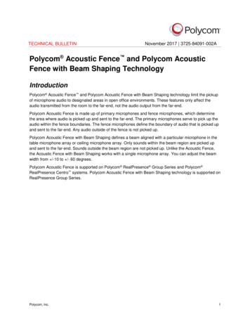
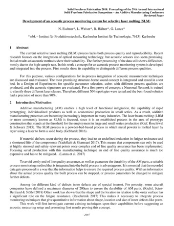
55. P. J. Westervelt, The Journal of the Acoustical Society of America 29, 1 (1957).56. G. G. Stokes, Mathematical and Physical Papers 1, 9 (1851).57. S. I. Rubinow and J. B. Keller, Journal of Fluid Mechanics 11, 447 (1961).58. G. Kirchhoff, Vorlesungen uber mathematische Physik: Mechanik (B.G. Teubner, Leipzig,1883).59. P. P. Brown and D. F. Lawler, Journal of Environmental Engineering 129, 222 (2003).60. B. Oesterlé and T. B. Dinh, Experiments in Fluids 25, 16 (1998).61. N. Lukerchenko, Y. Kvurt, A. Kharlamov, Z. Chara, P. Vlasak, J Hydrol Hydromech 56(2008).62. O. Sawatzki, Acta Mechanica 9 (1970).63. H. Bruus, Lab on a Chip 12, 1014 (2012)64. S. D. Danilov and M. A. Mironov, The Journal of the Acoustical Society of America 107,143 (2000).Supplementary FiguresPhase: -π - π/Amplitude: 0 – 2000 PaaX: 3cmbcdefghiY: 3cmZ: 4cm20mmFigure S1: spherical cap (SC) setup a) phased array made of 54 transducers levitating a2mm EPS particle 1.5cm above the top using a regular vortex beam ( ℓ 1). b,c,f,g)amplitude plots. d,e,h,l) phase plots. b,f,d,h) simulations. c,g,e,l) experimental measures.b,c,d,e) longitudinal slices. f,g,h,l) transve rsal slices.7
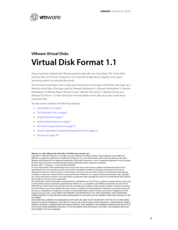
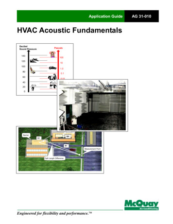
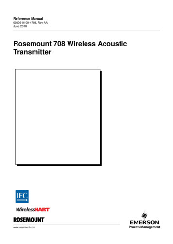
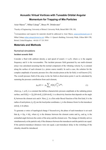
4x Driver BoardsPower SupplyPhased Array(Big bowl)Figure S2: open spherical sector (OSS) Setup. The array has 192 transducers and the topdiameter is 195mm.Figure S3: Schematic of the timing diagram of the driving signals in a Virtual Vortex andthe resulting forces. a) Force from the positive and negative (b) chirality vortex. c)modulation signal for the positive and (d) negative vortex.8
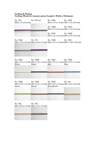
0.509080706050403020100-0.5-1Z position (mm)100-1.5-2N-( )Figure S4: Experimental dropping of a particle depending on the spe ed of multiplexation,if the virtual vortex chirality is multiplexed faster than 40 periods (1ms in our case) it canbe seen that the force decreases. Experiments repeated 5 times with 1.5mm diameter particleinside a 𝒱𝒱1 generated by the SC at 15Vpp. Error bars represent standard deviation.RV1RV3RV5VV1VV3VV5 21.8Time to ejection (s)1.61.41.210.80.60.40.2005101520Particle diameter (mm)Figure S5: Simulated ejection Plots for different types of vortices and particles diameter,we removed gravity to avoid droppings from insufficient z -force. The device was the OSS.The particles are considered stably trapped after two seconds.9
Figure S6: Simulated trajectory plots of 1mm, 2mm and 4mm particles inside a 𝒱𝒱1 vortexgenerated by the SC at 15Vpp. Units in meters.Figure S7: a) Levitation of a 1cm diameter Expanded Polystyrene particle (weight 10 μg)in a 𝒱𝒱3 using the OSC. Simulated amplitude fields in the XY(b) and XZ(c) planes.Simulated phase fields in the XY(d) and XZ(e) planes. f) Simulated force along X or Ydirections. g) Simulated force along Z direction. Units in me ters.10
1.6mm2mm3mm 2Time to ejection 30.350.4Switching Time (s)Figure S8: Simulated time to ejection depending on the switching time between the chiralityof the vortices for a 𝒱𝒱1 generated by the SC with a 15Vpp signal. F or particles of 1.6mmdiameter the switching speed needs to be faster than 1200 periods (30 ms), for particles of2mm 5000 periods (13 ms), and for particles of 3mm 1000 periods (2 ms). The particles areconsidered stably trapped after two seconds.Airwaterblood 2Seconds to 55.5Particle diameter (mm)Figure S9: Simulated time to ejection in a regular acoustic vortex 𝑅𝒱1 generated with theSC depending on the drag coefficient of the medium and the particle size. Air (density 1.18kg/m3, absolute viscosity 0.00002 Pa/s), water (1000 kg/m3, 0.001 Pa/s), blood (1060 kg/m3,0.003 Pa/s). The particles are considered stably tra pped after two seconds.11
2Time to Ejection (s)1.81mm particle1.61.2 mm1.41.210.80.60.40.200123456X Initial Position (mm)Figure S10: Simulated time to ejection depending on the initial position of particles of1mm and 1.2mm diameter inside a 𝒱𝒱1 generated by the SC with a 15Vpp signal. The plotpresents a binary threshold suggesting that initial position inside the trap is not influentialfor the stability as long as the particle is placed within 3mm of the trap centre. The particlesare considered stably trapped after two seconds.bamplitudeacField AField BamplitudeTime (2.5ms)dTime(0.5ms)Figure S11: Amplitude measure of two switching fields. a) switch every 30 periods (750 μs),b) 20 periods (500μs) and c) 10 periods (250 μs). It can be seen that the switching is notimmediate and that as the frequenc y of switching increases, the current field is during lesstime at the target field. d) Response of a transducer fed with a 15Vpp half -square signal.12
21.85VppTime to Ejection 2.53Particle diameter (mm)Figure S12: Simulated time to ejection
Acoustic Virtual Vortices with Tuneable Orbital Angular Momentum for Trapping of Mie Particles Asier Marzo1*, Mihai Caleap 1*, Bruce W. Drinkwater 1Faculty of Engineering, University of Bristol. University Walk, Bristol BS8 1TR. UK. *Correspondence and requests for materials