Transcription
View metadata, citation and similar papers at core.ac.ukbrought to you byCOREprovided by UNT Digital LibraryPlasma and Beam Production Experiments withHYBRIS, a Microwave-assisted H- Ion Source*R. Keller,a J. Kwan,b S. Hahto,c M. Regis,b and J. Walligba) Los Alamos Nat. Laboratory, P. O. Box 1663, Los Alamos, NM 87545, USAb) Lawrence Berkeley Nat. Laboratory, 1 Cyclotron Road, Berkeley, CA 94720, USAc) SemEquip, Inc., 34 Sullivan Road, North Billerica, MA, USAAbstract. A two-stage ion source concept had been presented a few years ago, consisting of aproven H- ion source and a 2.45-GHz Electron Cyclotron-Resonance (ECR) type ion source,here used as a plasma cathode. This paper describes the experimental development path pursuedat Lawrence Berkeley National Laboratory, from the early concept to a working unit thatproduces plasma in both stages and creates a negative particle beam. Without cesiation appliedto the second stage, the H- fraction of this beam is very low, yielding 75 micro-amperes ofextracted ion beam current at best. The apparent limitations of this approach and envisagedimprovements are discussed.Keywords: Negative hydrogen ion source, electron cyclotron resonance ion sourcePACS: 52.27.CmINTRODUCTIONNext-generation Proton Drivers that include an accumulator ring will have to relyon H- ion sources with key performance parameters in the areas of beam current, dutyfactor, and time-between-services that exceed the present state-of-the-art by a widemargin. A novel concept for creating intense beams of negative hydrogen ion beamshad been presented earlier on1 with a description of the first steps towards itsrealization. In this ‘HYBRIS’ approach, an Electron Cyclotron Resonance (ECR) ionsource2, 3 operating at 2.45 GHz frequency is utilized as a primary plasma generatorand coupled to an SNS-type multi-cusp H- ion source.4, 5 This secondary sourceutilizes the plasma electrons produced in the first stage and is driven by pulsed d. c.,rather than rf, power in a cold-cathode configuration, thus avoiding the use offilaments which are the cause for the short lifetimes of conventional H- sources or ofan internal rf antenna that is a performance-limiting element in the present version ofthe SNS ion source. Initial tests were performed to assess two aspects of this approach:1), to check the functionality of the available SNS ion source, the so-called startupsource that is identical to the delivered SNS production units in all major technicaldetails, driven by 2-MHz rf power as usual; and 2), to measure the maximum intensityof an electron beam that could be extracted from the ECR plasma generator operatedin c. w. mode.*This work was supported by the US Department of Energy under Contract Numbers DE-AC52-06NA25396 and DE-AC0205CH11231
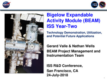
In the second phase, the two plasma generators were attached to each other, startingwith an attempt to create an electron beam and decelerate it upon injection into the Hplasma vessel, and then modifying the configuration on the base of experimentalfindings. This phase ended in a closely coupled system where the outlet electrode ofthe ECR chamber was identical to the cathode of the H- chamber. The last phase dealtwith improving the negative-ion detection system and performing plasma densitymeasurements in the multi-cusp chamber.EARLY EXPERIMENTSThe performance verification test of the SNS ‘start-up source’4 driven by 45 kW of2-MHz rf power but without cesium activation gave a positive result, with a measuredion current value of 15 mA. With a cesiated collar, three times more H- beam currenthad routinely been generated during the earlier SNS tests. In the initial HYBRISconfiguration, see Figures 1 and 2, electron beams of up to 1.5 A current wereextracted from the ECR chamber at 5 kV extraction voltage and decelerated to about100-eV energy upon injection into the H- discharge chamber. The attempt to strike adischarge in the multi-cusp chamber, however, failed because the gas pressure in thischamber was too low, and when more hydrogen gas was fed directly into this secondchamber to raise the pressure there, a discharge was struck, instead, in the electronextraction gap near the ECR chamber, and the electron beam could not be acceleratedat all under these conditions.FIGURE 1. Schematic of HYBRIS in its initial configuration.
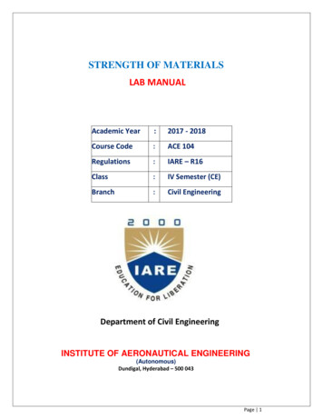
Therefore the configuration was changed, eliminating the elaborate electronextraction system entirely and positioning the ECR outlet aperture a few mm upstreamof the cold-cathode aperture. After several attempts, a weak discharge could finally bestruck in the multi-cusp chamber when the ECR chamber was held on the samepotential as the cold cathode.FIGURE 2. Electrical circuit of HYBRIS in its first configuration. Voltages and currents givenrepresent the nominal values; operational values were actually lower than those.IMPROVED SOURCE CONFIGURATIONIn the most recent configuration, the ECR chamber is directly coupled to the multicusp chamber, with the ECR outlet flange being replaced by the cold cathode itself,see Figures 3 and 4. Electrons are now transferred to the multi-cusp chamber byambipolar diffusion, and in this configuration, a discharge in the multi-cusp chambercan be readily ignited.The price for achieving the cold-cathode discharge ignition lies in the reduction ofsystem versatility: With the formerly used electron beam extraction system the energyof the electrons injected into the multi-cusp chamber could in principle have beenadjusted to arbitrary values. With this option lost, primary electrons might have to bedamped down in the main discharge itself if their initial energy upon injection werefound incompatible with high survival rates of H- ions produced inside the cesiumcollar. This damping effect could be achieved by extending the length of the multicusp chamber, thus enhancing the collision rates between primary electrons and coldparticles. No such effort was actually undertaken during the last experiments reportedhere.
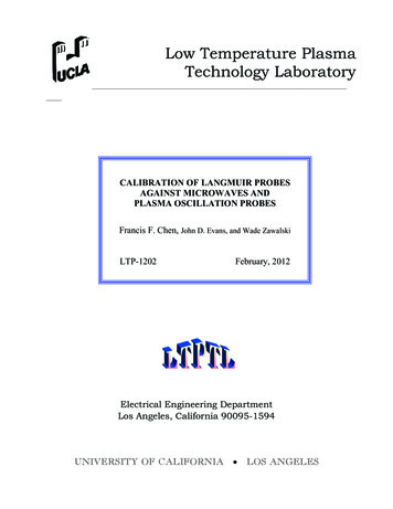
FIGURE 3. Schematic of HYBRIS in its most recent configuration.FIGURE 4. Electrical circuit of HYBRIS in its most recent configuration. Voltages and currents givenrepresent the nominal values; operational values were actually lower than those.As a major result with the improved HYBRIS configuration, a discharge current ofup to 17.5 A could be generated in the multi-cusp chamber with the forward microwave power at the maximum amplitude of 1.9 kW, a gas flow of 35 sccm, and 150 Veffective discharge voltage. The reflected microwave power, however, amounted to
450 W under these conditions, indicating that the plasma density in the ECR chamberhad reached the cut-off level at 1.45 kW and additional forward power was just gettingreflected. An example of a slightly lower discharge current pulse is shown in Fig. 5.Extension of the flat discharge pulse for a duration of 2 ms at less than 6% duty factorwas demonstrated as well. The axial magnetic field strength on the ECR chamber axismarginally exceeded the resonance level of 845 G over the entire length of thechamber, with the implication that exact resonance conditions are achieved on thesurface of an elongated, ellipsoid-like, volume that intersects the dielectric windowupstream on a narrow circle.FIGURE 5. Demonstration of a 15.2-A discharge pulse with 1.1 ms duration at 6.6% duty factor, in themulti-cusp chamber of HYBRIS.The first, very brief, attempt of extracting a beam of negative particles from the Hplasma vessel did not result in observing any H- ions in the presence of 8 mA electroncurrent. Due to significant noise on the current signal, the measurement resolution forthe ion current during this test was about 0.5 mA. To investigate the reason for theobserved, unexpectedly poor, performance and possibly arrive at design improvements, the geometry of the two-chamber Faraday cup was revised, and the dischargewas examined with a Langmuir probe.FINAL RESULTSThe two-chamber Faraday cup used in all negative-particle beam measurements wasrebuilt on the base of trajectory simulations with the code PBGuns.6 Figure 6 shows asimulation representing the optimized layout. The complete separation of electronsand negative ions in this cup was demonstrated experimentally as well, by operatingthe source with helium that does not form negative ions.
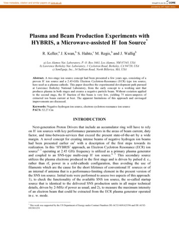
FIGURE 6. PBGuns simulation of the extraction diode and the two-chamber Faraday cup at a beamenergy of 5 keV.The Langmuir probe measurements showed that the current density in the multi-cuspchamber only reached values of 20 mA/cm2 at 1 kW forward power, whereas densitiesof 200 – 300 mA/cm2 have been measured in 2.45-GHz ECR ion sources. It was alsoobserved that striking a discharge in the multi-cusp chamber perturbs the ECRdischarge itself, making impedance matching harder to achieve. The H- and electronbeam current values obtained at 200 V discharge current in the multi-cusp chamber aredisplayed in Figure 7. The results show that the electron/ion current ratio is ratherconstant and, with a value of about 500/1, very high even considering that the collarwas not cesiated. Another finding was that the ion density in the multi-cusp chamberincreased with rising discharge voltage, but values above 200 V are consideredimpractical because the average electron energy would rise too much for H- ions tosurvive.Collectorcurrent0.1000.0800.060Ion (mA)E lect(500 mA)0.0400.0200.000050010001500Microwave power (W)FIGURE 7. H- and electron beam currents at voltages of 200 V (discharge) and 10 kV (extraction).
OUTLOOKBased on all experimental evidence gathered so far we have to conclude that thefundamental idea of combining an ECR discharge with a cold-cathode discharge ismeeting with considerable difficulties and has only slim chances for actuallysucceeding. The main problems appear to be the insufficient plasma density achievedin the multi-cusp chamber and excessive primary electron energies originating fromthe ECR discharge. The experiences gained, however, have led to a new attempt ofdeveloping a hybrid H- ion source where a helicon plasma device is being used insteadof a 2.45-GHz ECR discharge.7REFERENCES1. R. Keller, P. Luft, M. Regis, J. Wallig, M. Monroy, A. Ratti, D. Syversrud, R. Welton and D. Anderson, “AHybrid Ion-Source Concept for a Proton Driver Front-End,” AIP Conf. Proceedings 773, American Inst. ofPhysics, Melville, NY, 2005, pp. 104–106.2. T. Taylor and J. S. C. Wills, “A high-current low-emittance dc ECR proton source,” Nucl. Instr. Methods A309, 37 (1991).3. The ECR ion source was kindly loaned to us by Argonne National Laboratory. Assistance by J. Nolen, R. Pardoand R. Scott is thankfully acknowledged.4. R. Keller, R. Thomae, M. Stockli and R. Welton, “Design, Operational Experiences and Beam ResultsObtained with the SNS H- Ion Source and LEBT at Berkeley Lab,” AIP Conf. Proceedings 639, AmericanInstitute of Physics, Melville, NY, 2002, pp. 47 - 60.5. R. F. Welton, M. P. Stockli, S. N. Murray and R. Keller, “The status of the spallation neutron source ionsource,” Rev. Scientific Instrum. 75 (5), 1793-1795 (2004).6. J. E. Boers, PBGUNS Manual, available through Thunderbird Simulations, Garland, TX, 75042, USA.7. O. O. Tarvainen, M. Light, G. Rouleau and R. Keller, “Helicon Plasma-generator Assisted Negative-Ion-SourceProject at the Los Alamos Neutron Science Center,” these Symposium Proceedings, PNNIB-11, Santa Fe, Sept.13-15, 2006.
realization. In this 'HYBRIS' approach, an Electron Cyclotron Resonance (ECR) ion source2, 3 operating at 2.45 GHz frequency is utilized as a primary plasma generator and coupled to an SNS-type multi-cusp H-ion source.4, 5 This secondary source utilizes the plasma electrons produced in the first stage and is driven by pulsed d. c.,