Transcription
PC-4000 User ManualModel: 801125-5/801125-6 Copyright 2014 Panoramic CorporationUMD20000 Rev C
Table of ContentsIntroductionPurposeStatement of CompatibilityWarning of Voltage RegulatorsX-Ray Shielding RequirementsIntended Use3-533555Symbols & Definitions6PC-4000 Pan Pre-Patient SetupPC-4000 Pan Patient PositioningPrepare The PatientPosition The PatientSet The kVpRecheck Patient PositioningTake The ExposureRelease The Patient9-1010-1210111112121213-14Digital Image Enhancement13Image Processing14User Image Processing14Setting up the Image RepositoryPC-4000 TMJ Pre-Patient SetupPC-4000 TMJ Patient PositioningPrepare The PatientPosition The PatientSet The kVpRecheck Patient PositioningTake The ExposureRelease The Patient1516-181616171717-1818PC-4000 Bitewing Pre-Patient SetupPC-4000 Bitewing Patient PositioningPrepare The PatientPosition The PatientSet The kVpRecheck Patient PositioningTake The ExposureRelease The Patient1920-22202021212122Panoramic RadiographyMaintenance ScheduleAccessory OrdersPC-4000 LabelingPC-4000 SpecificationsPC-4000 Space RequirementsPC-4000 (MVT1000)2324252627-2829302Phone 800.654.2027www.pancorp.comfax 260.489.5683
IntroductionPurposePanoramic Corporation provides this printed manual as a guide for the operation of the PC-4000 dental panoramic X-raymachine.The PC-4000 will enable the user to take panoramic X-ray images.It is imperative that this equipment be installed, serviced, and used by personnel familiar with the precautions required toprevent excessive exposure to both primary and secondary radiation. This equipment features protective designs for limitingboth the primary and secondary radiation produced by the X-ray beam. However, design features cannot preventcarelessness, negligence, or lack of knowledge.Only personnel authorized by Panoramic Corporation are qualified to install and service this equipment. Any attempt toinstall or service this equipment by anyone not so authorized will void the warranty.Statement of Compatibility - January 1, 1988Please address any comments/questions concerning this statement of compatibility to:Panoramic Corporation 4321 Goshen Road Fort Wayne, IN 46818 USAThe only components compatible with the PC-4000 are those supplied with the machine.Regardless of possible statements made by other manufacturers, no one is authorized or certified to make additions ordeletions to this machine. Only the combination of components delivered with the machine is certified compatible bythe manufacturer. As compatible accessories become available, Panoramic Corporation will certify them as compatibleand make them available to the user.Statement of Compliance - December 17, 2004The PC-4000 conforms to the following specifications:X-ray Generator type: Single phase, half-wave, self rectified, center-grounded in accordance withIEC 60601-2-7:1998Phone 800.654.2027www.pancorp.comfax 260.489.56833
IntroductionSafety(Class B Device; Shock, Fire, Casualty) IEC 60601-1 Medical Electrical Equipment - Part 1: General Requirements for Safety IEC 60601-1:1998 A1:1991 A2:1995 Medical electrical equipment - Part 1-1: General requirements for safety Collateralstandard: Safety requirements for medical electrical systems IEC 60601-2-7:1998 Medical electrical equipment - Part 2-7: Particular requirements for the safety of high-voltage generators ofdiagnostic X-ray generators IEC 60601-2-28:1993 Medical electrical equipment - Part 2: Particular requirements for the safety of X-ray source assemblies andX-ray tube assemblies for medical diagnosis IEC 60601-2-32:1994 Medical electrical equipment - Part 2: Particular requirements for the safety of associated equipment of Xray equipment EN 60601-1:1990 A1:1993 A2:1995 A3:1996 Medical electrical equipment - Part 1-1: General requirements for safety Collateral standard: Safety requirements for medical electrical systems CAN/CSA C22.2 NO. 601-1-M90 A1:1994 A2:1998 Medical Electrical Equipment - Part 1: General Requirements for SafetyX-Ray Evaluation IEC 60601-1-3:1994 Medical electrical equipment - Part 1: General requirements for safety - 3. Collateral standard: Generalrequirements for radiation protection in diagnostic X-ray equipmentSoftware Review IEC 60601-1-4:1996 A1:1999 Medical electrical equipment - Part 1-4: General requirements for safety - Collateral Standard:Programmable electrical medical systemsEMC(Class B Device): EN 60601-1-2:2001 (IEC 60601-1-2:2001) Medical electrical equipment - Part 1-2: General requirements for safety - Collateralstandard: Electromagnetic compatibility - Requirements and tests EN 55011:1998 A1:1999 A2:2002 Industrial, scientific and medical (ISM) radio-frequency equipment - Radio disturbancecharacteristics - Limits and methods of measurement EN 61000-3-2:2000 Electromagnetic compatibility (EMC) - Part 3-2: Limits - Limits for harmonic current emissions (equipmentinput current 16 A per phase) EN 61000-3-3:1995 A1:2001 Electromagnetic compatibility (EMC) - Part 3-3: Limits - Limitation of voltage changes, voltagefluctuations and flicker in public low-voltage supply systems, for equipment with rated current 16 A per phase and notsubject to conditional connection EN 60601-1-2:2001 (IEC 60601-1-2:2001) Electromagnetic Compatibility - Requirements and TestsElectromagnetic compatibility (EMC)- Part 4-2: Testing and EN 61000-4-2:1995 A1:1998 A2:2001 (IEC 1000-4-2)measurement techniques - Electrostatic discharge immunity testElectromagnetic compatibility (EMC) - Part 4-3: Testing and measurement techniques EN 61000-4-3:2002 (IEC 1000-4-3)Radiated, radio-frequency, electromagnetic field immunity testElectromagnetic compatibility (EMC) - Part 4-4: Testing and EN 61000-4-4:1995 A1:2001 A2:2001 (IEC 1000-4-4)measurement techniques - Electrical fast transient/burst immunity testElectromagnetic compatibility (EMC)- Part 4-5: Testing and measurement EN 61000-4-5:1995 A1:2001 (IEC 1000-4-5)techniques - Surge immunity testElectromagnetic compatibility (EMC) - Part 4-6: Testing and measurement EN 61000-4-6:1996 A1:2000 (IEC 1000-4-6)techniques - Immunity to conducted disturbances, induced by radio-frequency fieldsElectromagnetic compatibility (EMC) - Part 4-8: Testing and measurement EN 61000-4-8:1993 A1:2001 (IEC 1000-4-8)techniques - Power frequency magnetic field immunity test EN 61000-4-11:1994 A1:2001 (IEC 1000-4-11) Electromagnetic compatibility (EMC) - Part 4-11: Testing and measurementtechniques - Voltage dips, short interruptions and voltage variations immunity tests4Phone 800.654.2027www.pancorp.comfax 260.489.5683
IntroductionVoltage Regulator WarningDo not plug this machine into ANY voltage regulating device. Contact Panoramic Corporation with any questions regardingthis.X-ray Shielding RequirementsThe requirements for panoramic and cephalometric shielding for building, operator, and patient, depend on state and localregulations. Contact your state Department of Health for compliance information. Compliance could involve a blueprintreview, facility check, wall construction, film badge implementation, remote switch installation, and/or a lead apron. It isbeyond the scope of this manual to advise on these regulations.Intended UseAn extraoral source X-ray system is an AC-powered device that produces X-rays and is intended for dental radiographicexamination and diagnosis of diseases of the teeth, jaw and oral structures.Warning StatementsWarning: This X-ray unit may be dangerous to patient and operator unless safe exposure and operating instructions areobserved.During installation, machine is leveled to the floor. Do not move/transport the machine before contacting PanoramicCorporation Service Department at (800)654-2027.Notice: Ground reliability can only be achieved when this equipment is connected to a hospital only or hospital gradereceptacle.The use of accessory equipment not complying with the equivalent safety requirements of this equipment may lead to areduced level of safety of the resulting system. Consideration relating to the choice of accessory equipment shall include:use of the accessory in the patient vicinity evidence that the safety certification of the accessory has been performed in accordance to the appropriate IEC 60601-1 and/or IEC 60601-1-1 harmonized national standard.Portable and mobile RF Communications equipment can affect medical electrical equipment.Original document created in English.Panoramic Corporation requires anyone moving or transporting their machine to contact the service Department at (800)654-2027.Phone 800.654.2027www.pancorp.comfax 260.489.56835
Symbols and DefinitionsSYMBOLSAlternating CurrentType B EquipmentAttention, Consult Accompanying DocumentsOn (power: connection to the mains)Off (power: disconnection from the mains)Dangerous VoltageProtective Earth (ground)Environmental SpecificationsOperating Temperature:Storage/Transportation Temperature:Operating Humidity:Storage/Transportation Humidity:Operating Altitude:Storage/Transportation Altitude:10oC to 40oC (50oF to 105oF)-25oC to 70oC (-13oF to 158oF)80% maximum relative humidity, noncondensing80% maximum relative humidity, noncondensing15,000 ft (4,500 m) maximum15,000 ft (4,500 m) maximumCleaning and DisinfectionThe following parts on the PC-4000 come into contact with the patient during normal operation:Black ChinrestTemple SupportsForehead SupportHandlesUse 70% Isopropyl Alcohol or Germicidal cloths (or equivalent) to clean and disinfect these parts.Do not attempt to clean any parts while machine is switched on.Mode of OperationContinuous operation with short time loading.Electrical SafetyClass I, Type B Applied PartsEquipment is classified as ordinary equipment (enclosed equipment without protection against ingress of water).Equipment not suitable for use in the presence of FLAMMABLE ANESTHETIC MIXTURE WITH AIR or WITH OXYGEN orNITROUS OXIDE.6Phone 800.654.2027www.pancorp.comfax 260.489.5683
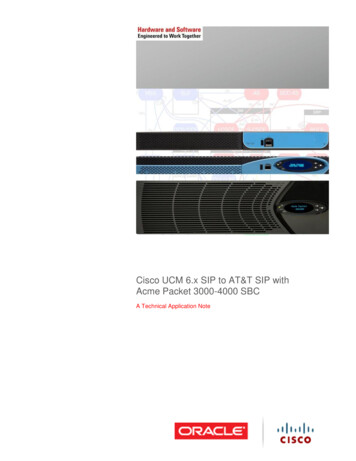
PC-4000 ComponentsTop CoverRotating ArmForehead SupportTemple SupportsTubeheadMirrorDigital SensorDisplay PanelChinrestExposure SwitchHandlesBasePhone 800.654.2027www.pancorp.comfax 260.489.56837
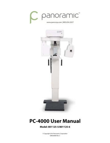
PC-4000 User InterfaceAllows user toselect functionor increasevalueAllows user toselect functionor decreasevalueExposureIndicatorAccepts flashingvalue or moveto program tonext screenAllows you toscroll to thenext screenAllows you tomove back oneScreen, andafter exposure,allows userto reset therotating armTurns machineon and offMoves machine upin the user mode andscrolls up the menu’sin‐service mode8Phone 800.654.2027Moves machine downin the user mode andscrolls down the menu’sin‐service modewww.pancorp.comfax 260.489.5683
PC-4000 Pan Pre-Patient Setup1. Press POWER on the front of the control panel.The screen will now display:PANORAMICCORPORATION2. Press MODEThe screen will now display:SELECT OPERATIONPAN L(Select from TMJ L, TMJ R, BTW L, BTW R, Pan L or Pan R)To scroll, press the Adjust buttons ( ) , (-) to select the functionyou wish to use.3. Press ENTER after the selection is made.4. Press MODE to move to the next screenThe screen will now display:ARM NOT POSITIONEDorARM POSITIONED5. If not positioned, press ENTER. The rotating arm will now reset tothe “home” position for the operation you have selected.6. Press MODE to move to the next screenThe screen will now display your selected operation:PAN LKVP: 80.0 (the number will be flashing)7. Select the correct panoramic rotation direction from the softwarescreen on the Dell computer. The software must match the settingon the panoramic units control panel.Example: PC‐4000 ProgramSelectionPhone 800.654.2027www.pancorp.comfax 260.489.56839
PC-4000 Pan Patient Positioning8. Using the knob at the rear of the forehead support, adjustthe forehead support toward the mirror to allow room forpositioning the patient.9. Slide the temple supports apart to allow room for positioningthe patient’s head.10. Using the UP/DOWN switch on the control panel, adjust thechinrest arm until it is slightly higher than the patient’s chin. This willensure that the patient stands up as straight as possible.11. If a stool is to be used, place the stool so that the seat is centeredunder the chinrest. This will help ensure that the patient’s neck isstraight.Prepare The Patient1. Ask the patient to remove any metal objects, such as glasses,earrings, removable dentures, hearing aids, hair pins, neck chains, bibchains, and collar zippers from their head and neck area. These objectscan prevent X-rays from reaching the sensor, causing poor diagnosticquality images.2. If a lead apron is used, and a panoramic poncho is not available,place the lead apron on the patient’s back. Ensure that it does not coverthe back of the neck. As the tubehead rotates around the patient, theX-rays pass through the head at a slight upward angle. This allows theX-ray beam to pass through the skull more efficiently by avoiding thedenser area of the patient’s skull.3. Guide the patient into the PC-4000. Use the UP/DOWN buttons onthe control panel to adjust the chinrest arm until it is slightly higherthan the patient’s chin. This will ensure that the patient is standing upas straight as possible.Caution: It is the responsibility of the operator to ensure noobstructions exist during column movement due to surroundingsand/or patient. Movement can be terminated by releasing theUP/DOWN buttons.4. Have the patient hold onto the handles and move his/her feet underthe chinrest. This will help ensure that the patient’s neck is straight.5. Place the appropriate chinrest on the permanent, blackchinrest on the chinrest arm:a. Small Child – Removable, black plastic chinrest may be neededto allow the child’s forehead to reach the forehead support.b. Adolescent and Adult – No additional chinrest. Majority ofpatients require no additional chinrest.c. Edentulous – Removable, clear plastic chinrest. Aids in centeringand consistently positioning the patient.10Phone 800.654.2027www.pancorp.comfax 260.489.5683
6. If the patient is not edentulous, insert a disposable bite-guide in thepermanent, black chinrest. Have the patient bite on the disposablebite-guide. Ensure that the bite-guide is centered between thecentral incisors. For edentulous patients, have the patient bite on a1 1/2” cotton roll to keep the maxilla and mandible separated.Position The Patient1. Place your hand at the base of the patient’s skull and apply pressurevertically to stretch the neck while slowly lowering the machineuntil the patient’s Frankfort Plane is horizontal (parallel to the redguidelines on the temple supports).The Frankfort Plane is the imaginary line from the middle of the earopening to the bottom of the eye orbit. A level Frankfort Plane willensure that the upper and lower anterior teeth are in one vertical planeand will help stretch the patient’s neck enough to allow X-rays to passbetween the vertebrae.2. Using the knob on the rear of the forehead support, adjust theforehead support until it touches the patient’s forehead.3. Center the patient’s head using the red line on the forehead support.Turn the mirror to see the patient to verify centering.4. Gently slide the temple supports against the patient’s head. Thesewill help keep the patient centered and measure the width of theskull to determine the amount of kVp required to penetrate theskull.Set The kVp1. Note which number the arrow points to on the kVp scale decal onthe outside of the temple support rod.2. Press the Adjust /- buttons to adjust the kVp setting per the templesupports. Plus ( ) will increase the reading, (-) will decrease thereading. KVP range is 70.0-90.0 adjustable by 2.5 increments.3. Press ENTER once the correct kVp setting is selected to lock in thevalue.The screen will now display:ADJUSTING KVP4. Press MODE to move to the next screen. Exposure LED light willilluminate to solid green and screen will now display:PAN L80.0 KVPPhone 800.654.2027www.pancorp.comfax 260.489.568311
PC-4000 Pan Patient PositioningRe-check Patient Positioning1. Ensure that the:a. patient’s chin is firmly seated on the chinrestb. patient’s feet positioned directly beneath support handlesc. patient’s head is centeredd. patient’s Frankfort Plane is horizontale. patient’s neck is stretchedf. patient’s forehead is resting on the forehead supportg. temple supports are against the patient’s headh. control panel indicates proper kVp through temple supportrodTake The Exposure1. Instruct the patient to close his/her lips around the disposable biteguide, swallow, place his/her tongue on the roof of his/her mouth,and remain still during the exposure. This will help equalize tissuedensities and help prevent unwanted artifacts and blurring.2. Depress exposure button, screen will display WARMUP INPROGRESS and have a slow beep (5-6 seconds). Exposure willthen start, LED light will now display on Control Panel indicatingRadiation is present and the rotating arm will begin to rotate aroundthe patient. When exposure is complete, release the exposurebutton and move temple supports out.Caution: It is the responsibility of the operator to ensure noobstructions exist during arm rotation due to surroundingsand/or patient. Movement can be terminated by releasing theExposure button.Release The Patient1. Slide the temple supports away from the patient’s head torelease the patient.2. Raise bite guide.3. Instruct the patient to step out of the machine.4. The screen will now display:PANORAMICCORPORATION5. Press the RESET button and the machine will return to the “home” position.6. Dispose of bite guide.For additional information a training video titled “PC-4000How to take a successful Digital Pan” is available on ourwebsite www.pancorp.com. From the PanoramicCorporation homepage select the Customer Tab, thenTraining Videos, and select the PC-4000 Training Videofrom the list.12Phone 800.654.2027www.pancorp.comfax 260.489.5683
Digital Image EnhancementImage ProcessingThe image processing tab contains several enhancement tools forsmoothing, sharpening and edge enhancing. These tools may beapplied to an image in any order or combination and can be easilyundone using the undo button. Below is a description of each tool.1.Denoise LowpassApplies lowpass filtering with a Gaussian kernel to the image. Thistool helps to remove normal (white) noise from the image to makean image appear smoother or less noisy. Several levels of this filterare available by right clicking on the tool and selecting a differentsize.2.Denoise MedianApplies median filtering to the image. Median filtering smoothesthe image by removing the salt and pepper type of noise thatappears as dots in the image. Several levels of this filter are availableby right clicking on the tool and selecting a different size.3.SharpenSharpens an image by applying an unsharp mask method. Unsharpmasking enhances boundaries in the image so that the imageappears clearer. Additional degrees of sharpening may be selectedby right clicking the tool and choosing the desired filter size.4.Equal VerticalThe equal vertical tool adjusts the local brightness of an imageso that brighter areas appear less obvious. This tool is useful forevening the appearance of a panoramic image and diminishingthe bright artifacts caused by the spine.5.Vertical Edge EnhancementVertical edge enhancement is similar to sharpening but onlyvertical edges are enhanced.6.Horizontal Edge EnhancementHorizontal edge enhancement is similar to sharpening but onlyhorizontal edges are enhanced.Phone 800.654.2027www.pancorp.comfax 260.489.568313
User Image ProcessThe user image process area provides several user configurablebuttons that can be used to apply frequently used image processingtools as desired. One additional tool can be configured to applyimage processing automatically when images are acquired.Use the following steps to configure user button:1. Select and apply any smoothing, sharpening or edgeenhancement desired.2. Se
Panoramic Corporation provides this printed manual as a guide for the operation of the PC-4000 dental panoramic X-ray machine. The PC-4000 will enable the user to take panoramic X-ray images. It is imperative