Transcription
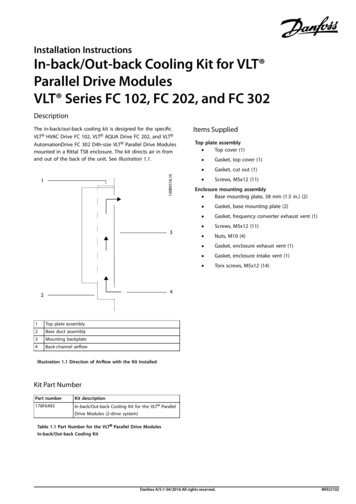
Installation InstructionsIn-back/Out-back Cooling Kit for VLT Parallel Drive ModulesVLT Series FC 102, FC 202, and FC 302DescriptionThe in-back/out-back cooling kit is designed for the specificVLT HVAC Drive FC 102, VLT AQUA Drive FC 202, and VLT AutomationDrive FC 302 D4h-size VLT Parallel Drive Modulesmounted in a Rittal TS8 enclosure. The kit directs air in fromand out of the back of the unit. See Illustration 1.1.Items SuppliedTop plate assembly Top cover (1) Gasket, top cover (1)Gasket, cut out (1)Screws, M5x12 (11)Enclosure mounting assembly Base mounting plate, 38 mm (1.5 in.) (2) 1Top plate assembly2Base duct assembly3Mounting backplate4Back-channel airflowGasket, base mounting plate (2)Gasket, frequency converter exhaust vent (1)Screws, M5x12 (11)Nuts, M10 (4)Gasket, enclosure exhaust vent (1)Gasket, enclosure intake vent (1)Torx screws, M5x12 (14)Illustration 1.1 Direction of Airflow with the Kit InstalledKit Part NumberPart numberKit description176F6493In-back/Out-back Cooling Kit for the VLT ParallelDrive Modules (2-drive system)Table 1.1 Part Number for the VLT Parallel Drive ModulesIn-back/Out-back Cooling KitDanfoss A/S 04/2016 All rights reserved.MI92J102
Installation InstructionsIn-back/Out-back Cooling Kit for VLT Parallel Drive ModulesVLT Series FC 102, FC 202, and FC 302SafetyLower duct assemblyWARNINGDISCHARGE TIMEThe frequency converter contains DC-link capacitors, whichcan remain charged even when the unit is off. High voltagecan be present even when the warning indicator lights areoff. Failure to wait 20 minutes after power has beenremoved before performing service or repair work, couldresult in death or serious injury. Stop the motor. Wait 20 minutes for the capacitors to discharge fully,before performing any service or repair work. Measure the voltage level to verify full discharge.Disconnect the AC mains, permanent magnet typemotors, and remote DC-link supplies, includingbattery back-ups, UPS, and DC-link connections toother frequency converters.1Gasket between drive module and top plate (1)2Top plate (1)3Gasket between duct enclosure and top plate (1)Installation4Gasket, top side (2)5Top side, cover (2)NOTICE6Gasket, side of grill (2)7Grill (1)8Gasket between grill and mounting backplate (1)9Front cover plate (1)10Gasket, between duct enclosure and front cover plate (1)NOTICE11Duct enclosure (1)APPROVALS AND CERTIFICATIONS12Gasket between duct enclosure and base cover plate (1)13Base cover plate (1)–Screws, M5x12 (4)–Torx screws, M5x16 (7)–Nuts, M5 (36)This VLT Parallel Drive Modules back-channel cooling kit isUL 508C compliant. These installation instructions describehow to install the back-channel cooling kit which, iffollowed, meet specific agency approvals and certifications.Seek agency approvals or certifications apart from Danfoss ifdesigning and building other configurations.If both a bus bar kit and a back-channel cooling kit arebeing installed in the cabinet, install the back-channelcooling kit first.Illustration 1.2 Lower Duct Assembly for 1 Drive ModuleNOTICEAPPLYING GASKETSThis kit contains gaskets to ensure a proper seal betweenmetal parts. Before adhering a gasket to a part, check thatthe part matches the gasket and that no holes are covered.Remove paper backing and place the sticky side on the part.2Danfoss A/S 04/2016 All rights reserved.MI92J102
Installation InstructionsIn-back/Out-back Cooling Kit for VLT Parallel Drive ModulesVLT Series FC 102, FC 202, and FC 302Creating Vent Openings in the Mounting BackplateRefer to Illustration 1.3 for these steps.1.Cut out the intake and exhaust openings in the mounting backplate. The openings must match the drive module ventopenings.2.Drill the 12 screw holes around the exhaust (top) vent openings and insert the 12 M5 X 12 pem studs.3.Drill the 12 screw holes around the intake (bottom) vent openings and insert the 12 M5 X 12 pem studs.Illustration 1.3 Vent Dimensions for Mounting PlateMI92J102Danfoss A/S 04/2016 All rights reserved.3
Installation InstructionsIn-back/Out-back Cooling Kit for VLT Parallel Drive ModulesVLT Series FC 102, FC 202, and FC 302Assembling the Lower Duct EnclosureThe front cover gasket (10) and front cover plate (9) are not installed during the lower duct assembly. They are installed once theduct is attached to the mounting backplate.1.Install the left and right side gaskets (6) against the back side of the duct enclosure (11).2.Place the grill (7) on top of the gaskets. Secure the grill to the enclosure using 4 M5 nuts. Torque to 5.1 Nm (45 in-lb).3.Install the gasket (8) on top of the grill.4.On the base of the enclosure, install the gasket (12) and then the base cover plate (13) on the enclosure. Secure with 10M5 nuts and torque to 5.1 Nm (45 in-lb).5.On the top of the enclosure, install the gasket (3) and then the top plate (13) on the enclosure. Secure the top plate tothe enclosure with 4 M5 nuts. Torque to 5.1 Nm (45 in-lb).6.Install the gasket (1) on the top plate. Leave the paper backing on the adhesive until ready to install on the drive module.7.Turn the duct enclosure over so the base of the enclosure is facing up. Install the top side gaskets (4) on the sides of thetop plate (2).8.Place a top side cover (5) on each gasket (4). Secure each cover with 5 M5 nuts and torque to 5.1 Nm (45 in-lb).Illustration 1.4 Assembling the Lower Duct Enclosure1Gasket between drive module and top plate82Top plate9Front cover plate3Gasket between duct enclosure and top plate10Gasket between duct enclosure and front cover plate4Gasket, top side11Duct enclosure5Top side, cover12Gasket between duct enclosure and base cover plate6Gasket, side of grill13Base cover plate7Grill––4Gasket between grill and cabinetDanfoss A/S 04/2016 All rights reserved.MI92J102
Installation InstructionsIn-back/Out-back Cooling Kit for VLT Parallel Drive ModulesVLT Series FC 102, FC 202, and FC 302Mounting the Drive Modules1.Install the mounting backplate to the cabinet rails, making sure that the pem studs/nuts are facing toward the back of theenclosure.2.Install gaskets to the back side of the drive module. Refer to Illustration 1.5.3.2aInstall gasket (3) over the exhaust vent opening.2bAlign the slot gasket (5) with the lower mounting holes in the drive module and install the gasket onto thedrive module.Install the base mounting plates. Refer to Illustration 1.6.3aAssemble the 2 base mounting plates by attaching the gasket (4) onto the base mounting plate (5).3bInsert an M10 screw (6) through the mounting plate/gasket assembly and loosely fasten into the mountingbackplate. Perform this step again for the other mounting plate/gasket assembly. Make sure that the screws aresecure since the base of the drive module rests on these screws.4.Slightly lean the top of the drive module forward and set the cutouts in the base of the module onto the lower 2 M10screws in the mounting backplate.5.Slowly push the top of the drive module back against the mounting backplate until the top 2 holes on the module lineup with the 2 mounting holes in the mounting backplate. Secure the top of the drive module using 2 M10 screws andtorque to 19 Nm (170 in-lb).6.Torque the M10 screws securing the base of the module to 19 Nm (170 in-lb).7.Install the top plate assembly. Refer to Illustration 1.5.MI92J1027aPlace the gasket (3) over the grill opening on the top of the unit.7bPlace the top cover (1) over the gasket. Secure it with the 11 screws included in the kit.Torque to 5.1 Nm (45 in-lb).Danfoss A/S 04/2016 All rights reserved.5
Installation InstructionsIn-back/Out-back Cooling Kit for VLT Parallel Drive ModulesVLT Series FC 102, FC 202, and FC 3021Top cover on drive module4Mounting backplate2Gasket between drive module exhaust and top cover5Gasket, slot3Gasket, between drive module exhaust and mountingbackplate––Illustration 1.5 Installing the Drive Modules to the Mounting Back Plate6Danfoss A/S 04/2016 All rights reserved.MI92J102
Installation InstructionsIn-back/Out-back Cooling Kit for VLT Parallel Drive ModulesVLT Series FC 102, FC 202, and FC 302Installing the Lower Duct Assembly to the Mounting BackplateRefer to Illustration 1.6 for the following steps.1.Remove the paper backing from the top plate gasket.2.Place the lower duct assembly up against the drive module base, making sure the mounting holes line up.3.Secure the lower duct assembly to the base of the drive module using 7 M5x16 screws. Torque to 5.1 Nm (45 in-lb).4.Secure the grill on the lower duct assembly to the mounting backplate using 4 M5x12 screws. Torque to 5.1 Nm(45 in-lb).5.On the front side of the lower duct, install the front cover gasket (10) and then the front cover plate (9). Refer toIllustration 1.4. Secure with 8 M5 nuts and torque to 5.1 Nm (45 in-lb).6.Install the lower duct assembly for the next drive module.1Drive module5Base mounting plate, 38 mm (1.5 in)2Gasket, slot6M10 screw3Cutout in drive module base that rests on the M10 screw7M5x16 screw4Gasket, base mounting plate, 38 mm (1.5 in)8Lower duct assemblyIllustration 1.6 Installing the Lower Duct AssemblyMI92J102Danfoss A/S 04/2016 All rights reserved.7
Installation InstructionsIn-back/Out-back Cooling Kit for VLT Parallel Drive ModulesVLT Series FC 102, FC 202, and FC 302Installing the Back Panel Cover81.Install a gasket (1) around each exhaust vent opening on the back side of the mounting backplate (4). Refer toIllustration 1.7.2.Install a duct spacer (2) onto each exhaust gasket and secure with 4 M5 nuts. Torque to 5.1 Nm (45 in-lb).3.Install a gasket (5) around each intake vent opening on the back side of the mounting backplate (4).4.Install an intake duct spacer (6) onto each intake gasket and secure with 4 M5 nuts. Torque to 5.1 Nm (45 in-lb).5.Place a gasket (3) onto each exhaust duct spacer.6.Place a gasket (7) onto each intake duct spacer.7.Prepare the back panel cover. Refer to Illustration 1.8.7aCut out the 2 intake and 2 exhaust vent openings in the back panel. The openings must match to the intake andexhaust duct spacer openings.7bDrill the 16 screw holes around the vent openings.8.Secure the back panel cover to the frame.9.Secure the back panel cover to the duct spacers with 16 M5x16 screws. Torque to 5.1 Nm (45 in-lb).Danfoss A/S 04/2016 All rights reserved.MI92J102
Installation Instructions1In-back/Out-back Cooling Kit for VLT Parallel Drive ModulesVLT Series FC 102, FC 202, and FC 302Gasket between the mounting backplate and the exhaust duct5Gasket between the mounting backplate and the intake duct spacerDuct spacer, exhaust6Duct spacer, intake3Gasket between the exhaust duct spacer and the back panel7Gasket between the intake duct spacer and the back panel4Mounting plate––spacer2Illustration 1.7 Installing the Duct SpacersMI92J102Danfoss A/S 04/2016 All rights reserved.9
Illustration 1.8 Vent Dimensions for Back Panel CoverDanfoss can accept no responsibility for possible errors in catalogues, brochures and other printed material. Danfoss reserves the right to alter its products without notice. This also applies to products already onorder provided that such alterations can be made without subsequential changes being necessary in specifications already agreed. All trademarks in this material are property of the respective companies. Danfossand the Danfoss logotype are trademarks of Danfoss A/S. All rights reserved.Danfoss A/SUlsnaes 1DK-6300 2J102*04/2016
The in-back/out-back cooling kit is designed for the specific VLT . On the base of the enclosure, install the gasket (12) and then the base cover plate (13) on the enclosure. Secure with 10 M5 nuts and torque to 5.1 Nm (45 in-lb). 5. On the top of the enclosure, install the gasket (3) and then the top plate (13) on the enclosure.