Transcription
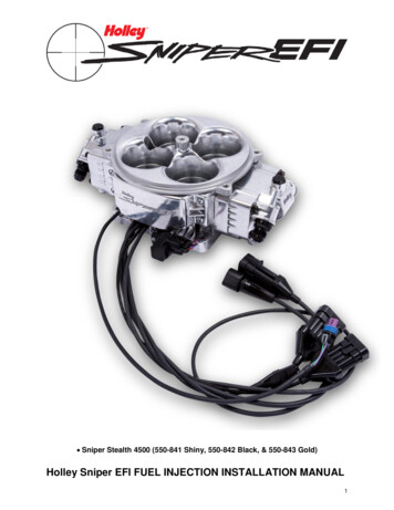
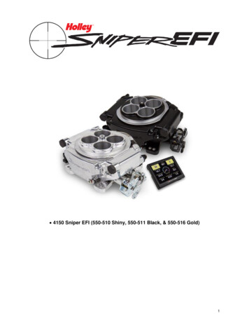
4150 Sniper EFI (550-510 Shiny, 550-511 Black, & 550-516 Gold)1
Holley Sniper EFI FUEL INJECTION INSTALLATION MANUALRead this manual before using this product.WARNING!This instruction manual must be read and fully understood before beginning installation. If the instructionsare not fully understood, installation should not be attempted. Failure to follow the instructions may result insubsequent system failure and could result in serious personal injury and/or property damage. Keep thismanual.For the safety and protection of you and others as well as your vehicle, only a trained mechanic havingadequate fuel system experience should perform the installation, adjustment, and repair.While undertaking any work involving the fuel system, it is particularly important to remember one of the verybasic principles of safety: fuel vapors are heavier than air and tend to collect in low places where an explosivefuel/air mixture may be ignited by any spark or flame resulting in property damage, personal injury, and/ordeath. Extreme caution must be exercised to prevent spillage and thus eliminate the formation of such fuelvapors. All work involving this product and the fuel system generally MUST be performed in a well-ventilatedarea. Do NOT smoke or have an open flame present near gasoline vapors or an explosion may result.Any components damaged due to failure to follow these instructions will not be covered by the warranty.Failure of any one component does not constitute, nor does it justify, warranty of the complete system.Individual service items are available for replacement of components. If assistance is required or if you needfurther warranty clarification, please call Holley Technical Service at 1 (270) 781-9741.2
TABLE OF CONTENTSINTRODUCTION & SYSTEM REQUIREMENTS . 5Engine Requirements . 5Fuel System Requirements .5TOOLS REQUIRED FOR INSTALLATION . 5PARTS IDENTIFICATION . 6THROTTLE BODY INSTALLATION . 6OXYGEN SENSOR INSTALLATION . 8COOLANT TEMPATURE SENSOR INSTALLATION . 10FUEL SYSTEM CONNECTIONS . 10SNIPER EFI MASTER FUEL SYSTEM INSTALL . 11Fuel Pump and Filter Installation . 12Return Line Bulkhead Fitting Installation . 12Fuel Line Installation . 14Hose Assembly . 14ECU WIRING OVERVIEW . 16BASIC WIRING INSTALLATION. 17GENERAL WIRING REFERENCE. 18Throttle Body Connections . 18Pigtail & Loose Wire Connections. 18Connecting Sniper EFI Touchscreen LCD to Sniper EFI . 19NON TIMING CONTROLLED IGNITION SYSTEM WIRING . 22Coil (-) [No Timing Control] . 22Ignition Box Tach Output [No Timing Control] . 23TIMING CONTROLLED IGNITION SYSYEM WIRING . 25Timing Control Preface: . 25MSD (Magnetic) Distributor [Timing Control] . 25Holley Dual Sync Distributor [Timing Control] . 30HANDHELD NAVIGATION . 36Possible Screens . 36INITIAL EFI SETUP . 38Calibration Wizards. 38Sensor Verification. 41Prestart Checklist. 42First Startup . 42After Startup. 42Ignition Timing Check [Without Timing Control] . 43Ignition Timing Check [ECU Controlling Timing] . 43THROTTLE BLADE ADJUSTMENT . 44SYSTEM SETUP . 45Ignition System Setup . 45BASIC TUNING. 46Basic Fuel . 463
Target AFR . 47Acceleration Enrichment . 47Fuel Prime . 48Closed Loop Enable/Disable . 48Learn Enable/Disable . 49Basic Idle . 49Spark . 50SYSTEM TUNING. 50Outputs . 50Engine Setup . 52Sniper Setup . 52Ignition Setup . 53Static Timing . 53ADVANCED TUNING . 54IAC Rampdown. 56Idle Spark . 57Idle Speed . 58SNIPER EFI MONITOR . 59Monitors . 59Multi-Gauge . 59Changing Monitor Channel Scaling . 60Custom Configuring Dash 1 Dash 2 or Dash 3 . 60NITROUS TUNING ON HANDHELD . 61BOOST CONTROL ON HANDHELD . 61ADVANCED TABLES ON HANDHELD . 61TUNING DEFINITIONS . 62DATALOGGING & FILE TRANSFERS . 71Taking a Datalog with the 3.5” TSCLCD . 71Downloading Global Configuration from Sniper EFI Throttle Body to SD card: . 72Loading Calibration into Sniper EFI ECU . 72LAPTOP SUPPORT. 73Viewing Global Configuration with Sniper EFI Software without USB Cable: . 73Viewing Datalog with Sniper EFI Software: . 74TROUBLESHOOTING . 75Troubleshooting Guide . 75Sensor Verification. 75Sensor Diagnostics and Statuses . 754
INTRODUCTION & SYSTEM REQUIREMENTSHolley Performance Products has written this manual for the installation of the Sniper EFI TBI fuel injection system.This basic manual contains the information necessary for the installation of the throttle body, wiring, and sensors.Please read all the WARNINGS and NOTES, as they contain valuable information that can save you time and money.It is our intent to provide the best possible products for our customer; products that perform properly and satisfy yourexpectations.Engine RequirementsBefore moving forward with the installation, please verify your vehicle meets the engine and fuel system requirementsbelow: Engine is in sound mechanical conditionEngine horsepower is between 200-650Engine is a naturally aspirated (no supercharger, turbocharger, etc.) 4, 6 or 8 cylinderEngine has a 4 barrel, 4150 style flange intake manifold*Unleaded fuel onlyAny RTV silicone sealants used on the engine are sensor safe* Any 4150 flange intake manifold will work. Make sure to use proper gaskets to seal the throttle body to the intakemanifold and ensure that there are no vacuum leaks.Fuel System RequirementsThe Sniper EFI system requires a high pressure fuel pump capable of operating at 60 psi with at least 50 gallon perhour of fuel flow (more fuel flow may be needed for higher horsepower engines). When selecting a pump, and lines, besure each component is designed to perform at high pressure. Holley offers a variety of fuel pumps, hoses andaccessories to complete your installation. For best results, Holley strongly recommends an in-tank pump. Installing thefuel pump in the tank results in quieter operation, less chance of cavitation and a reduction in pump temperature. Ifmounting the pump in the tank is not an option, install the pump as close as possible to the tank. Within 2-feet ofsending unit is recommended. Once the fuel system is installed checking the fuel pressure on the inlet side of theSniper EFI is recommended, fuel pressure needs to be between 55-65 PSI.The 550-510K, 550-511K, and 550-516K fuel injection systems include the complete fuel system.TOOLS REQUIRED FOR INSTALLATION Standard Wrench SetMedium Blade ScrewdriverDrill and Assorted Bit SizesFactory Service Manual for your vehicle Small Blade Screwdriver #2 Phillips Screwdriver Terminal Crimping Tool 7/8” Drill Bit (step-bit recommended) Allen Wrench Set Digital VoltmeterAn assistant is necessary for some installation and adjustment procedures and should be present for safety reasons.WARNING! Before disconnecting the battery, we recommend locating a Clean Switched 12 volt ignition source.This source needs to have 12 volts while cranking and with the key in the run position. Disconnect batterybefore proceeding with any work to the vehicle.5
PARTS IDENTIFICATIONITEM #IMAGEDESCRIPTIONQTYBosch Wide BandOxygen Sensor1Clamp-on OxygenSensor Bung211SERVICE P/NNOTES Use of leaded fuel will degrade sensor.Prolongedusewillrequireperiodicreplacement. Mounting procedure below is critical for systemperformance Requires 3/4” hole to be drilled Mounting procedure below is critical for systemperformance In order to help prevent condensation in theexhaust from damaging the sensor, ensurethat the sensor is installed with at least 10degrees of vertical angle.3/8” NPT Threads – Adapters to ½” NPT areavailable554-15571014302RHKR CoolantTemperatureSensor31Sniper EFIThrottle BodyAssembly15Air CleanerGasket193.5” TouchScreen Controller110Output Harness111Main Harnessand IgnitionAdapter14543-120 Must be installed in a coolant passage in eitherthe intake manifold or cylinder head. Do notinstall in thermostat housing. 4150 Flange Sniper EFI Throttle BodyN/A Includes ECU, fuel injectors, Manifold AirPressure (MAP) sensor, Throttle PositionSensor (TPS), Manifold Air Temp Sensor(MAT), and an Idle Air Control Valve (IAC)553-115 Includes harness to connect directly to CANconnector558-491 Mates to Input/Output connector on MainWiring Harness and can be used for A/CShutdown, Electric Fan #1 Output, and/orElectric Fan #2 Output.558-490THROTTLE BODY INSTALLATION1.Start by labeling all vacuum lines for easy identification, i.e. brake booster & vacuum advance for distributor. Ifany lines appear damaged, now is the time to replace them. Next, remove the carburetor, clean the gasketmating surface, and install the provided intake flange gasket on the intake manifold.2.Place the Sniper EFI throttle body on top of the new flange gasket on the manifold. Install the hold down nutsand snug down progressively in a “criss-cross” pattern (60-80 in./lbs.). Depending on your application, this isalso the time to install your throttle bracket and transmission kickdown brackets. You may be able to re-use thestock style throttle stud or transmission studs from your carburetor.6
3.Throttle Linkage/Bracket Side View4.Reconnect the throttle and if applicable transmission kick-down linkage. Be sure to check for any bindingconditions and correct before proceeding. Poorly routed throttle cables & linkages can cause throttle pedalissues.5.Reconnect the appropriate vacuum hoses to the Sniper EFI throttle body. Be sure to plug any vacuumsources not used on both the Sniper EFI Throttle Body and on the Engine.Vacuum Port Side View7
OXYGEN SENSOR INSTALLATIONWARNING!Failure to disconnect the AIR pump or locating the oxygen sensor downstream from AIR injection will result in anextremely rich mixture, which could cause drivability problems and severe engine damage. If disconnecting AIRpump, check with local ordinances for the legality of this procedure in your area.Your vehicle may already have an O2 sensor bung welded into the exhaust. This bung location needs to be verifiedbefore using it with the Oxygen sensor included in the Sniper EFI system. Ideally the bung will be 6-10 inches after thecollector for a true reading of all cylinders and have a minimum of 18” length past the sensor location. If the vehicle isequipped with a catalytic converter, the bung must be between the engine and the catalytic converter. The bung alsomust be on the top side of the tube so moisture cannot collect on the oxygen sensor. If there is an acceptable bungalready present, go ahead and tighten the oxygen sensor supplied with your Sniper EFI in the bung. If there is not anacceptable bung already in the exhaust, please plug all poorly placed bungs and follow the following instructions forthe included Clamp-On O2 bung.If needed, Hooker Blackheart offers different diameter Clamp-On O2 Bung kits:2.25” Diameter: 71014303-RHKR2.50” Diameter: 71014302-RHKR3.00” Diameter: 71014301-RHKR1.Locate a position for the oxygen sensor as close to the engine as possible. The oxygen sensor should bemounted at a point where it can read a good average of all the cylinders on one bank. This would be slightlyafter all the cylinders merge. If you have long tube headers, mount the sensor approximately 6-10” after thecollector. You must have at least 18” of exhaust pipe after the sensor.2.If your vehicle has catalytic converters, the oxygen sensor MUST be located between the engine and thecatalytic converters. It is also CRITICAL that the oxygen sensor is NOT installed in the bottom of the exhausttube. This will help prevent condensation in the exhaust tubing from entering the sensor. The clamp-on kitinstallation requires a 3/4 hole to be drilled in the exhaust system. Refer to main installation manual for moredetails.NOTE: Verify that the O2 cable is supported correctly and away from heat sources such as theexhaust. If the O2 cable has melted it is not something fixed under warranty and will require theunit to be sent back to Holley to be repaired at customer cost.3.Ensure the location for the sensor is at the angle in Figure 1. This will help prevent condensation in the exhausttubing from entering the sensor. The sensor can be mounted on either side of the tubing.Figure 14.Mark the center of the casting on the exhaust tube and drill a 3/4" hole. Deburr the hole after drilling (Figure 2).Figure 28
5.Place the gasket on the tube (Figure 3), then the casting on the tube (Figure 4). Slip a clamp on one side andlightly tighten. Slip the second clamp on and lightly tighten (Figure 5). It is necessary to use a small amount ofanti-seize on the threads of the T bolt clamps to prevent thread damage.Figure 3Figure 4Figure 5NOTE: Never run the engine with the oxygen sensor installed if it is not plugged in and powered by the ECU, or itwill be damaged. If you need to plug the hole temporarily, use an O2 sensor plug or a spark plug with an18mm thread.9
COOLANT TEMPATURE SENSOR INSTALLATIONInstall the Coolant Temperature Sensor into a 3/8” NPT coolant passage in either the intake manifold or cylinder head.Do not overtighten or damage to the cylinder head or intake may occur. It is best to drain the some of the coolant beforethe sensor is installed. Use thread sealer or a small amount of thread tape. Do not install the sensor in the thermostathousing, or in an area that will not see a constant flow of coolant.FUEL SYSTEM CONNECTIONSConnect fuel feed and return hose. It is mandatory that the fuel outlet/return comes from the fuel pressure regulatorand the fuel inlet must go to one of the three options for the inlet fitting on the 4150 Sniper EFI. The inlets and outletare indicated in Fuel Fitting Overview below. The Sniper EFI System comes with a built in fuel pressure regulator,factory set at 58.5psi. We recommend at least a 3/8” feed line and 3/8” return line.Note: Fuel pressure should be checked on the inlet fuel line before initial start up during the fuel pump prime. Werecommend Earl’s Part number 100187ERL (0-100 psi Liquid filled gauge) & AT100199ERL (-6AN Gauge Adapter) tocheck fuel pressure.Fuel Fitting OverviewDANGER! Take precautions to ensure that all fuel components are away from heat sources, such as theengine or exhaust pipes. A fire or explosion hazard could cause serious injury or death!DANGER! Before disconnecting or removing fuel lines, ensure the engine is cold. Do not smoke.Extinguish all open flames. An open flame, spark, or extreme heat near gasoline can result in afire or explosion causing property damage, serious injury, and/or death.DANGER! Never get under a vehicle supported only by a jack. Serious injury or death can result fromvehicles falling off of jacks. Before working underneath a vehicle, support it solidly with jackstands.10
SNIPER EFI MASTER FUEL SYSTEM INSTALLIf you did not purchase a master fuel system Sniper EFI Kit, please make sure your fuel system is plumbed properly.Can use the guidelines below to verify it is correct. If you would like to purchase the fuel system components that comein the master fuel system Sniper EFI kits, part number 526-5 and 526-7 are available for purchase.ITEM123457891011DESCRIPTIONUniversal Electric Fuel Pump20 FT - 3/8 I.D. EFI Vapor Guard Hose3/8” Vapor Guard Hose ClampsPost Fuel Filter 10 micronPre Fuel Filter-6AN to 3/8” Vapor Guard Hose EndFuel Cuff (240MM long)9/16” Stat-O-Seal-6AN Bulkhead Nut-6AN Bulkhead Fitting1728QTYSERVICE PART111111312212225752066ERL750006ERLHolley P/N 562-1 or NAPA P/N 3482NAPA P/N 1111
Fuel Pump and Filter InstallationThe following section covers the installation of the in-line pump as well as the pre and post filters. The fuel pumpMUST be mounted lower than the lowest part of the fuel tank, and as close to the tank as possible. The fueltank must also be properly vented.1.Use below as a reference for the orientation and location of the fuel system components:2.Mount the electric fuel pump as close to the fuel tank outlet as possible with the bracket provided. Mounting thefuel pump in this manner will insure that the pump will prime easily to ensure faster starts.3.There are two filters included with this kit. The pre-filter (Item 5) MUST be installed between the fuel tank and thefuel pump inlet (unless an in-tank pump is used in place of the pump in this kit). The purpose of this filter is toprotect the fuel pump from particles of dirt or other foreign material. The filter should be installed with the arrowon the filter pointing in the direction of the fuel flow.4.The post-fuel filter (Item 4) should be installed between the electric pump outlet and TBI unit. This is a 10 micronEFI filter. Position the filter, so the fuel hoses can be routed without kinks or sharp bends. The filter should beinstalled with the arrow on the filter pointing in the direction of the fuel flow.WARNING! Ensure both filters are installed in the proper direction. A flow direction arrow is printed on theside of the filter to indicate the direction of fuel flow. Failure to do so will result in a systemmalfunction.Return Line Bulkhead Fitting InstallationThe Sniper EFI system requires a return fuel line to the fuel tank. This kit includes the hose and fittings necessary fora return line installation on most vehicles. Some late model vehicles that were originally equipped with a throttle bodyinjection system may already have a return line to the fuel tank that can be utilized. The return line must not present apressure restriction to the return fuel flow. There should never be more than approximately 3 PSI of pressure in thereturn line. A line that is too small, or has restrictions will cause tuning problems with the system.DANGER! Do not use the vapor canister lines as a fuel return line. Possible fuel leaks may create a fire orexplosion hazard, causing serious injury or death.12
DANGER! Proper installation of the fuel return line will necessitate complete removal of the fuel tank. Thiswork should be done by a fuel tank specialist, who regularly does this work and is familiar with safetyregulations and precautions necessary to do this work. If a person attempts this work, who is not familiar withthe safety regulations and precautions, an explosion hazard may result causing serious injury or death.Choose an ideal location for the bulkhead fitting to be installed. The fitting must be installed through a flat surface wherethe nut can be tightened from the bottom. It must also be installed in a location where the fuel cuff will not interfere withthe sending unit float. If possible, we strongly recommend removing, cleaning, and drilling into the sending unit. Thefitting must be oriented as shown below in Figure 44. The item numbers from section 27.1 are referenced.DANGER! IF DRILLING INTO TANK (RATHER THAN SENDING UNIT), HOLLEY RECOMMENDS HAVING YOURTANK PROFESSIONALLY CLEANED BEFORE DRILLING. IF YOU CHOOSE NOT TO HAVE THE TANKPROFESSIONALLY CLEANED, DRAIN THE TANK COMPLETELY, LET DRY, AND FILL WITH WATER.1.Drill a 9/16” hole and debur. Remove all metal shavings and particles from tank.2.Install bulkhead fitting with one Stat-O-Seal above the surface, and one below.3.Screw the bulkhead nut onto fitting from the bottom, inside of the tank. Snug with a wrench. A spare bulkheadnut has been provided and will not be used in this installation.4.Insert the barbed end of a straight Vapor Guard hose end (Item 7) into an end of the fuel cuff (Item 8) andensure the cuff covers both barbs.5.Slide hose clamp (Item 3) over fuel cuff and fitting and tighten to secure.6. Screw fuel cuff assembly to bottom of bulkhead nut and snug with a wrench. Ensure bottom of cuff will besubmerged in fuel as shown in. Cuff can be trimmed if necessary.13
Fuel Line InstallationWith the
Jan 3, 2022