Transcription
Integrating Meraki Networks withCisco Identity Services EngineSecure Access How-To guide seriesAuthors: Tim Abbott, Colin LowenbergDate: April 2016Table of ContentsIntroduction
Compatibility MatrixOverviewComponentsNetwork DiagramMeraki Wireless Network ConfigurationConfigure Meraki Wireless Group PolicyAdd ISE as a RADIUS Server for Dot1x SSIDAdd ISE as a RADIUS Server for Guest SSIDAdd ISE as a RADIUS Server for Wireless MAB SSIDMeraki Wired Network ConfigurationAdd ISE as a RADIUS Server for Wired 802.1XApply Access Policy to Switch PortsMeraki VPN Network ConfigurationConfigure Client VPN AccessISE ConfigurationEnable Policy SetsAdd Meraki Access Point as a Network Access DevicesAdd Meraki Switch as a Network Access DeviceAdd Meraki Security Appliance as a Network Access DeviceAdd Meraki Cloud RADIUS Clients as Network Access DevicesAuthorization ProfilesAllowed ProtocolsISE AAA ConfigurationCisco Systems 2016Page 2
Wireless Authentication RuleWireless 802.1X AuthenticationWireless MAB AuthenticationWireless Local Web AuthenticationWired 802.1X Authentication RuleRA VPN Authentication RuleWireless 802.1X AuthorizationCentral Web Authentication (CWA) ExamplesHotSpot ExampleSelf-Registered Guest ExampleSponsored Guest Guest ExampleBYOD Enrollment ExampleMDM Enrollment ExamplePosture Assessment ExampleWireless LWA AuthorizationWired Authorization PolicyRA VPN AuthorizationProfiling ConsiderationsWireless Network ProfilingWired Network ProfilingCisco Systems 2016Page 3
IntroductionThis configuration example illustrates how to use Cisco Identity Services Engine (ISE) to authenticate users attemptingaccess to Meraki wireless, wired, and VPN networks. ISE uses predefined Meraki Group Policies to assign networkusers an access policy based on group membership in Microsoft’s Active Directory (AD), Guest user credentials, orEndpoint information. The example uses the following Identity Groups: Employees, Contractors, Guests andWorkstations. Using these groups, the document outlines the steps necessary to configure 802.1X, MACAuthentication Bypass (MAB), Local Web Authentication (LWA), Central Web Authentication (CWA), RemoteAccess (RA) VPN and Profiling where applicable. For the latest documentation please visit the Cisco Merakidocumentation:Compatibility MatrixFeatureMR WirelessCompatibilityMX ApplianceCompatibilityMS tedSupportedSupportedMAC Authentication ByPassSupportedNot SupportedSupportedEnforcementSupportedNot SupportedNot SupportedPreconfigured Group policy(wireless).Local Web AuthenticationSupportedNot SupportedNot SupportedLocal captive portals (wireless).Device ProfilingSupportedLimited SupportLimited SupportRADIUS (Wired).Device PosturingSupportedLimited SupportLimited SupportRequires Inline Posture Node.Guest (Hotspot, Selfregister, Sponsored)SupportedLimited SupportLimited SupportGuest VLAN (Wired).Cisco Systems 2016DetailsPage 4
Central Web AuthenticationSupportedNot SupportedNot SupportedNetwork SupplicantProvisioning (NSP)SupportedNot SupportedNot SupportedChange of Authorization(CoA)SupportedNot SupportedNot SupportedNo URL-Redirect with sessioninformation or CoA (VPN/Wired)OverviewThis guide assumes that both ISE and a Meraki network have been installed and are functioning properly. A step-bystep guide on how to set up Meraki networks is available at http://docs.meraki.com. The Meraki wireless networksshould be configured with three SSIDs. The Meraki wired network should be configured with Employee and GuestVLANs. A subnet for RA VPN clients should also be identified. Cisco ISE will use AD as an external identity sourcefor user authentication and differentiated authorization policy assignment. Any AD groups intended for use inauthorization policy should be preconfigured in the ISE as well as Sponsored Guest Policy. Reference the ISE UserGuide for more information or how to configure Sponsored Guests and to integrate ISE with AD.Components Cisco ISE 1.3 or laterCisco Catalyst 3560-X SwitchCisco Meraki MR16 Access PointCisco Meraki MS42P SwitchCisco Meraki MX90 Security ApplianceCisco Meraki Cloud Management PlatformMicrosoft Active Directory 2008 R2Cisco Systems 2016Page 5
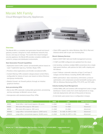
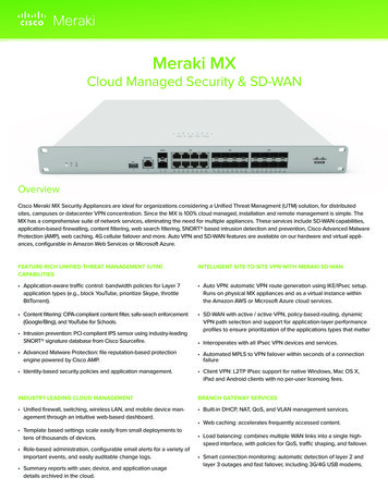
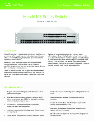
Network DiagramFigure 1.Network TopologyMeraki Wireless Network ConfigurationUsing Meraki Group Policies configure a Group Policy for the Employee and Contractor groups in AD. Then add ISEas the RADIUS server for the Dot1x, LWA/CWA and MAB SSIDs. Users who belong to the Employee or ContractorAD group will be able to connect to the Dot1x SSID. Users with Guest credentials will be able to connect to the LWASSID and devices belonging to the Workstation Endpoint Identity Group in ISE will be able to associate to the MABSSID.Configure Meraki Wireless Group PolicyStep 1.Step 2.Step 3.Step 4.Step 5.Step 6.Select the wireless network for use with ISE from the Network: drop down menu.Select Configure Group policies in the Meraki dashboard.Select Add a group.Name the group policy Employee.If needed, configure any group policy settings. Leave Splash as Use SSID Default.Click Save Changes.Cisco Systems 2016Page 6
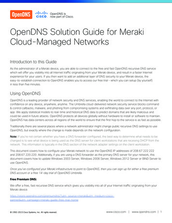
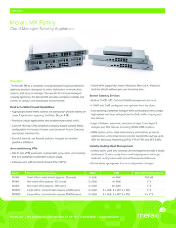
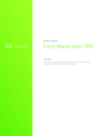
Step 7.Step 8.Step 9.Repeat steps 1 through 6 for the Contractor Group Policy.Repeat steps 1 through 6 for the Guest Group Policy.Repeat steps 1 through 6 for the Workstation Group Policy.Figure 2.Meraki Group PolicyAdd ISE as a RADIUS Server for Dot1x SSIDThis section shows an example configuration for an 802.1X-protected SSID using ISE as the RADIUS server. Duringauthentication, ISE tells the Cloud Management Platform which Group Policy to assign using the Airespace-ACLName RADIUS vendor specific attribute (VSA). In addition, selecting Cisco ISE for the splash page setting allows foradvanced use cases such as Native Supplicant Provisioning, MDM enrollment, and Posture Assessment.Step 1Under the Configure menu in the Meraki dashboard, select Access control.Step 2Select the SSID from the drop down menu that is used by the Employee Identity Group.Step 3Ensure the WPA2-Enterprise radio button is selected along with my RADIUS server in the dropdown menu.Step 4Select Cisco Identity Services Engine (ISE) Authentication.Step 5In the RADIUS servers field, enter the IP address, port 1812 and secret of the ISE policy servicenodes.Step 6Disable RADIUS testing.Step 7Enable RADIUS accounting.Step 8In the RADIUS accounting field, enter the IP address, port 1813 and secret of the ISE policy servicenodes.Step 9In the RADIUS attribute specifying group policy name field, select Airespace-ACL-Name.Cisco Systems 2016Page 7
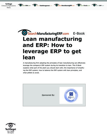
Step 10Step 11Step 12Step 13Step 14Ensure that Assign group policies by device type is disabled.Ensure that Walled garden is enabled, then add DNS and ISE policy service nodes.Select Bridge mode for Client IP Assignment.Set the VLAN tagging option to Don’t use VLAN tagging.Click Save Changes to complete the configuration of the SSID. Refer to figure 3 for an example.Note: Optionally, you may configure Per-User VLAN tagging in addition to the Group Policy assignment. ISE can tell the Cloud Management Platform whichVLAN to assign to the user. This method would allow you to further differentiate user groups and assign different access policies during authentication.Dot1x SSID Access ControlNetwork AccessAssociation RequirementsWPA2 Enterprise with my RADIUS server.Splash PageCisco Identity Services Engine (ISE)AuthenticationRADIUS ServersIP address, port 1812 and secret of ISE policyservice node(s)RADIUS TestingRADIUS testing disabledRADIUS AccountingRADIUS accounting is enabledRADIUS Accounting ServersIP address, port 1813 and secret of ISE policyservice node(s)RADIUS attribute specifying grouppolicy nameAirespace-ACL-NameWalled gardenEnabled, Add DNS and ISE policy servicenode(s)Assign group policies by device typeDisabled: Do not assign group policiesautomaticallyAddressing and trafficClient IP assignmentBridged Mode: Make clients a part of the LANVLAN taggingDon’t use VLAN taggingCisco Systems 2016Page 8
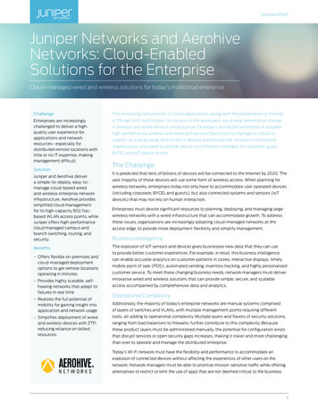
Figure 3.Dot1x SSID Access ControlAdd ISE as a RADIUS Server for Guest SSIDThis section shows an example of how to configure LWA using ISE as the RADIUS server. The captive portal webpage is served from the Cloud Management Platform and must be able to communicate with ISE across the Internet forcredential validation. The Meraki Security Appliance must be configured to allow RADIUS traffic on UDP ports1812 and 1813 from the Cloud Management Platform to ISE. Reference http://docs.meraki.com/ for informationon how to configured firewall rules on the Meraki Security Appliance. Guest credentials are created on ISE and sentto the guest user via the Sponsor Portal.Step 1Under the Configure menu in the Meraki dashboard, select Access control.Step 2Select the SSID from the drop-down menu that will be used by the Guest Identity Group.Step 3Ensure the Open (no encryption) radio button is selected for Association Requirements.Step 4Select Single sign-on for Splash Page and ensure my RADIUS server is selected from the drop downmenu.Step 5Under RADIUS for splash page, enter the publicly reachable IP address, port 1812 and secret ofthe ISE policy service node.Step 6Ensure that Assign group policies by device type is disabled.Step 7Select Bridge mode for Client IP Assignment.Step 8Set the VLAN tagging option to Use VLAN tagging.Step 9Under VLAN ID, select Add VLAN.Step 10Enter the AP Tag name for the Guest VLAN ID.Step 11For RADIUS override, select Ignore VLAN attribute in RADIUS responses.Step 12Click Save Changes to complete the configuration of the SSID. Refer to figure 4 for an example.Note: The AP Tag must be configured on the access point for the configuration to take effect and the link between the switch and access point must be a VLANtrunk. In this scenario, ISE will not need to assign the VLAN ID, as each user attempting to authenticate to the Guest SSID will use the Guest VLAN. See MerakiCloud Managed Wireless documentation for more information.Guest SSID Access ControlNetwork AccessAssociation RequirementsOpen (no encryption)Splash PageSign-on with my RADIUS serverRADIUS for splash pageIP address, port 1812 and secret of ISE policyservice nodesCisco Systems 2016Page 9
Assign group policies by device typeDisabled: Do not assign group policiesautomaticallyAddressing and trafficClient IP assignmentBridged Mode: Make clients a part of the LANVLAN taggingUse VLAN taggingVLAN IDAP Tag and VLAN ID of guest VLAN onupstream switchRADIUS overrideIgnore VLAN attribute in RADIUS responsesFigure 4.Guest SSID Access ControlAdd ISE as a RADIUS Server for Wireless MAB SSIDThis section will demonstrate how to use the new URL-Redirect and RADIUS CoA features of the Cisco Meraki MRAccess Points. With the addition of these new features, it is now possible to utilized Central Web Authentication(CWA) for advanced use cases with ISE and Meraki wireless networks.Step 1Under the Configure menu in the Meraki dashboard, select Access control.Step 2Select the SSID from the drop down menu that will be used by the Workstation Identity Group.Step 3Ensure the MAC-based access control (no encryption) radio button is selected for AssociationRequirements.Step 4Select Cisco Identity Services Engine (ISE) Authentication for Splash Page.Step 5In the RADIUS servers field, enter the IP address, port 1812 and secret of the ISE policy servicenodes.Step 6Disable RADIUS testing.Step 7Ensure RADIUS CoA support is enabled.Step 8In the RADIUS accounting field, enter the IP address, port 1813 and secret of the ISE policy servicenodes.Step 9In the RADIUS attribute specifying group policy name field, select Airespace-ACL-Name.Step 10Ensure that Assign group policies by device type is disabled.Step 11Ensure Walled garden is enabled and enter the IP addresses for your DNS and PSN serversStep 12Select Bridge mode for Client IP Assignment.Step 13Set the VLAN tagging option to Use VLAN tagging.Step 14Under VLAN ID, select Add VLAN.Step 15Enter the AP Tag name for the Workstation VLAN ID.Cisco Systems 2016Page 10
Step 16Step 17For RADIUS override, select Ignore VLAN attribute in RADIUS responses.Click Save Changes to complete the configuration of the SSID. Refer to figure 5 for an example.MAB SSID Access ControlNetwork AccessAssociation RequirementsMAC-based access control (no encryption)Splash PageCisco Identity Services Engine (ISE) AuthenticationRADIUS ServersIP address, port 1812 and secret of ISE policy servicenode(s)RADIUS TestingRADIUS testing disabledRADIUS AccountingIP address, port 1813 and secret of ISE policy servicenode(s)RADIUS attribute specifying grouppolicy nameAirespace-ACL-NameAssign group policies by device typeDisabled: Do not assign group policies automaticallyWalled gardenEnabled, Add DNS and ISE policy services node(s)Addressing and trafficClient IP assignmentBridged Mode: Make clients a part of the LANVLAN taggingUse VLAN taggingVLAN IDAP Tag and VLAN ID of Workstation (MAB) VLAN onup stream switchRADIUS overrideIgnore VLAN attribute in RADIUS responsesFigure 5.Cisco Systems 2016MAB SSID Access ControlPage 11
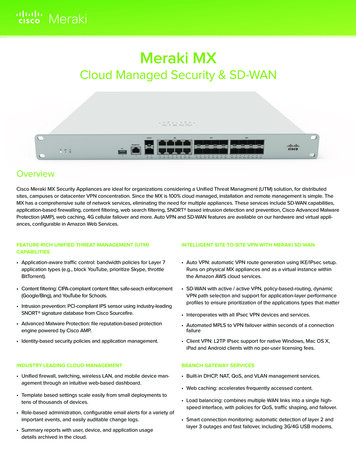
Meraki Wired Network ConfigurationThis section outlines the configuration steps necessary to use ISE as a RADIUS server for use with Meraki switches.Meraki switches operate in a closed mode. In contrast to Meraki wireless networks, you do not have the ability toapply Meraki Group Policy during authentication. Optionally, you may configure a guest VLAN. This is useful in theevent of authentication failure or for wired guest access to the network.Add ISE as a RADIUS Server for Wired 802.1XStep 1Step 2Step 3Step 4Step 5Step 6Step 7Step 8Step 9Step 10Select the wired network for use with ISE from the Network: drop down menu.Under the Configure menu in the Meraki dashboard, select Access policies.Select Add an access policy.Give the new policy a name. (For example, ISE).In the Host field, enter the IP address of the ISE node.In the Port field, enter 1812.In the secret field, enter the shared secret.Set RADIUS testing to RADIUS testing disabled.If desired, enter the Guest VLAN for use when users fail 802.1X authentication.Click Save.Note: Once configured, your new Access Policy should look similar to Figure 6.Figure 6.RADIUS Server configuration in Meraki DashboardApply Access Policy to Switch PortsStep 1Step 2Select Configure Switch ports.Select the desired switch ports to apply the Access policy.Cisco Systems 2016Page 12
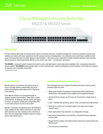
Step 3Step 4Step 5In the Access policy drop down menu, select the name of the Access Policy (For example, ISE).Click Update 1 port.Repeat steps 1 through 4 for each port intended to use this Access Policy.Note: Reference Figure 7 for a configuration example.Figure 7.Cisco Systems 2016Meraki switch port configurationPage 13
Meraki VPN Network ConfigurationConfigure Client VPN AccessStep 1Step 2Step 3Step 4Step 5Step 6Step 7Step 8Step 9Step 10Step 11Select the VPN network for use with ISE from the Network: drop down menu.Select Configure Client VPN in the Meraki dashboard.Set the Client VPN Server to Enabled.Enter a subnet that VPN Clients will use. (For example, 192.168.111.0/24)Select Specify nameservers from the DNS nameservers drop down menu.Enter the IP address(s) of internal DNS servers.Specify a secret that users will need to configure a L2TP over VPN client.From the Authentication drop down menu, select RADIUS.Click Add RADIUS server.Enter the IP address, Port and Shared Secret for the ISE node.Click Save.Note: Reference Figure 8 for a configuration example.Figure 8.Cisco Systems 2016Security Appliance RADIUS Server configurationPage 14
Cisco Systems 2016Page 15
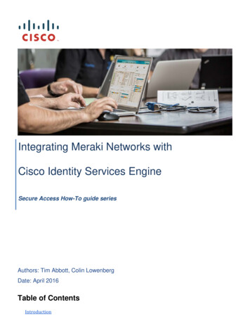
ISE ConfigurationIn this section, we first configure Policy Sets. Next, the Meraki access points and Cloud RADIUS Clients are addedinto the ISE deployment as network access devices. Then, configure an Authorization Profile for Employees,Contractors and Workstations. Configure allowed protocols for use in Authentication Policy. Finally, configureAuthentication and Authorization Policy.Enable Policy SetsStep 1Step 2Step 3Navigate to Administration Settings Policy Sets.Click Enabled.Click Save.Note: See Figure 9 for configuration example.Figure 9.Cisco Systems 2016Enable Policy SetsPage 16
Add Meraki Access Point as a Network Access DevicesStep 1Step 2Step 3Step 4Step 5Navigate to Administration Network Devices.Click Add to create a new network device.Enter a name for the Cisco Meraki access point.Enter the IP address of the access point.Define the Device Type and Location of the access point.Cisco Best Practice: Predefined Device Type and Location in the Network Device Groups menu. Putting all Meraki access points in a unique Device Typegroup will allow you to reference them in authentication and authorization policy later.Step 6Step 7Step 8Check the box for Authentication Settings and enter the shared secret.Click Submit.Repeat steps 1 through 7 for additional Meraki access points that will be used in the ISE deployment.Note: You have the ability to bulk import network access devices. Simply click on “Import” and then “generate a template.” Be sure to fill out all the requiredfields in the CSV template prior to uploading to ISE.Add Meraki Switch as a Network Access DeviceStep 1Step 2Step 3Step 4Step 5Step 6Click Add to create a new network device.Enter a name for the Cisco Meraki switch.Enter the IP address of the switch.Define the Device Type and Location of the access point.Check the box for Authentication Settings and enter the shared secret.Click Submit.Add Meraki Security Appliance as a Network Access DeviceStep 1Step 2Step 3Step 4Step 5Step 6Click Add to create a new network device.Enter a name for the Cisco Meraki security appliance.Enter the IP address for the access point.Define the Device Type and Location of the access point.Check the box for Authentication Settings and enter the shared secret.Click Submit.Note: To use Meraki LWA, you must add the Cloud Management Platform itself as a network access device (NAD). RADIUS requests from the CloudManagement Platform will come from one of four public IP addresses: 64.156.192.245, 64.156.192.68, 74.50.51.16, and 74.50.56.161. Create a NAD entry inISE for each public IP address. Please check Meraki documentation to ensure those public addresses are still in use.Add Meraki Cloud RADIUS Clients as Network Access DevicesStep 1Navigate to Administration Network Devices.Cisco Systems 2016Page 17
Step 2Step 3Step 4Step 5Step 6Step 7Step 8Click Add to create a new network device.Enter a name for the Meraki access point.Enter one of the IP addresses for the Cloud RADIUS client.Define the Device Type and Location of the access point.Check the box for Authentication Settings and enter the shared secret.Click Submit.Repeat steps 1 through 7 for the remaining three Cloud RADIUS Clients.Authorization ProfilesThis procedure outlines the process necessary to tie ISE Authorization Policy to Group Policy on the Cisco Merakiaccess point. We will create several Authorizations Profiles for use in Authorization Policy. For Cisco Merakinetworks that will not use a Group Policy, we use the prebuilt Authorization Profile PermitAccess in AuthorizationPolicy.Step 1Navigate to Policy Results Authorization Authorization Profiles.Step 2Click Add to create a new Authorization Profile.Step 3Name the Authorization Profile MerakiWirelessEmployee and leave the access type set toAccess Accept.Step 4Under Common Tasks, Check the box for Airespace ACL Name and enter Employee.Step 5Click Submit to save the new Authorization Profile.Step 6Repeat steps 1 through 5 and name the profile MerakiWirelessContractor and use Contractor forthe Airespace ACL Name.Step 7Repeat steps 1 through 5 and name the profile MerakiWirelessWorkstation and use Workstation forthe Airespace ACL Name.Step 8Repeat steps 1 through 5 and name the profile MerakiWirelessGuest and use Guest for theAirespace ACL Name.S
In addition, selecting Cisco ISE for the splash page setting allows for advanced use cases such as Native Supplicant Provisioning, MDM enrollment, and Posture Assessment. Step 1 Under the Confi