Transcription
The SWIFT XRT Data Reduction GuideVersion 1.2April 2005M. Capalbi, M. Perri, B. Saija, F. Tamburelli(ASI Science Data Center)&Lorella Angelini(HEASARC)
Contents1 INTRODUCTION11.1Scope . . . . . . . . . . . . . . . . . . . . . . . . . . . . . . . . . . . . . . . . . . . .11.2The Basic Scheme . . . . . . . . . . . . . . . . . . . . . . . . . . . . . . . . . . . . .11.3Organization of this Guide . . . . . . . . . . . . . . . . . . . . . . . . . . . . . . . . .21.4New releases and Updates . . . . . . . . . . . . . . . . . . . . . . . . . . . . . . . . .22 XRT modes32.1Introduction . . . . . . . . . . . . . . . . . . . . . . . . . . . . . . . . . . . . . . . . .32.2Description of XRT Modes. . . . . . . . . . . . . . . . . . . . . . . . . . . . . . . .42.2.1Photodiode modes . . . . . . . . . . . . . . . . . . . . . . . . . . . . . . . . .42.2.2Windowed Timing mode . . . . . . . . . . . . . . . . . . . . . . . . . . . . . .62.2.3Photon Counting mode . . . . . . . . . . . . . . . . . . . . . . . . . . . . . .72.2.4Image mode . . . . . . . . . . . . . . . . . . . . . . . . . . . . . . . . . . . . .82.3Classification of Events and Grade . . . . . . . . . . . . . . . . . . . . . . . . . . . .82.4XRT configuration: Changes post-launch . . . . . . . . . . . . . . . . . . . . . . . . .83 DATA FILES123.1Introduction3.2Basic file structure, Levels of Swift XRT Data and Filename . . . . . . . . . . . . . . 123.33.4. . . . . . . . . . . . . . . . . . . . . . . . . . . . . . . . . . . . . . . . 123.2.1Events FITS File Structure . . . . . . . . . . . . . . . . . . . . . . . . . . . . 123.2.2Image FITS File Structure . . . . . . . . . . . . . . . . . . . . . . . . . . . . 133.2.3The Levels of Swift XRT Data . . . . . . . . . . . . . . . . . . . . . . . . . . 133.2.4XRT file naming convention . . . . . . . . . . . . . . . . . . . . . . . . . . . . 13Main columns in Swift XRT FITS Events Files . . . . . . . . . . . . . . . . . . . . . 143.3.1RAWX/Y, DETX/Y, X/Y and OFFSET Columns . . . . . . . . . . . . . . . 143.3.2TIME and ROTIME Columns . . . . . . . . . . . . . . . . . . . . . . . . . . 153.3.3PHA, PHAS, GRADE and PI Columns . . . . . . . . . . . . . . . . . . . . . 163.3.4STATUS Column . . . . . . . . . . . . . . . . . . . . . . . . . . . . . . . . . . 163.3.5Other Relevant Columns . . . . . . . . . . . . . . . . . . . . . . . . . . . . . . 17Other relevant Swift XRT Data files . . . . . . . . . . . . . . . . . . . . . . . . . . . 17i
Swift XRT software Guideii3.4.1Housekeeping Files . . . . . . . . . . . . . . . . . . . . . . . . . . . . . . . . . 173.4.2Filter File . . . . . . . . . . . . . . . . . . . . . . . . . . . . . . . . . . . . . . 184 Data Reduction194.1Introduction . . . . . . . . . . . . . . . . . . . . . . . . . . . . . . . . . . . . . . . . . 194.2Stage 1. . . . . . . . . . . . . . . . . . . . . . . . . . . . . . . . . . . . . . . . . . . 204.2.1Photon Counting mode . . . . . . . . . . . . . . . . . . . . . . . . . . . . . . 204.2.2Photodiode and Windowed Timing modes . . . . . . . . . . . . . . . . . . . . 224.3Create a filter file: all modes . . . . . . . . . . . . . . . . . . . . . . . . . . . . . . . 254.4Stage 2: All modes . . . . . . . . . . . . . . . . . . . . . . . . . . . . . . . . . . . . . 254.5Stage 1 and 2 : Imaging mode . . . . . . . . . . . . . . . . . . . . . . . . . . . . . . . 264.6Calculating the attitude corrected for the TAM . . . . . . . . . . . . . . . . . . . . . 274.7How to run xrtpipeline . . . . . . . . . . . . . . . . . . . . . . . . . . . . . . . . . . . 285 SCREENING CRITERIA315.1Introduction . . . . . . . . . . . . . . . . . . . . . . . . . . . . . . . . . . . . . . . . . 315.2Screening Criteria associate with the ACS . . . . . . . . . . . . . . . . . . . . . . . . 315.3Screening Criteria Specific to the XRT . . . . . . . . . . . . . . . . . . . . . . . . . . 325.3.1Instrument Parameters. . . . . . . . . . . . . . . . . . . . . . . . . . . . . . 325.3.2Event characteristics . . . . . . . . . . . . . . . . . . . . . . . . . . . . . . . . 335.4Summary . . . . . . . . . . . . . . . . . . . . . . . . . . . . . . . . . . . . . . . . . . 345.5How to Screen the Data . . . . . . . . . . . . . . . . . . . . . . . . . . . . . . . . . . 355.5.1Example of How to Use xrtscreen . . . . . . . . . . . . . . . . . . . . . . . . . 355.5.2Example of How to Use xrtpipeline . . . . . . . . . . . . . . . . . . . . . . . . 355.5.3Example of how to use XSELECT . . . . . . . . . . . . . . . . . . . . . . . . 366 Extraction of Products386.1Introduction6.2Using XSELECT . . . . . . . . . . . . . . . . . . . . . . . . . . . . . . . . . . . . . . 386.3Setting Filters . . . . . . . . . . . . . . . . . . . . . . . . . . . . . . . . . . . . . . . . 406.4. . . . . . . . . . . . . . . . . . . . . . . . . . . . . . . . . . . . . . . . 386.3.1Grade Filtering . . . . . . . . . . . . . . . . . . . . . . . . . . . . . . . . . . . 406.3.2Region Filtering . . . . . . . . . . . . . . . . . . . . . . . . . . . . . . . . . . 416.3.3Time Filtering . . . . . . . . . . . . . . . . . . . . . . . . . . . . . . . . . . . 426.3.4Energy Filtering . . . . . . . . . . . . . . . . . . . . . . . . . . . . . . . . . . 436.3.5Intensity Filtering . . . . . . . . . . . . . . . . . . . . . . . . . . . . . . . . . 436.3.6Phase Filtering . . . . . . . . . . . . . . . . . . . . . . . . . . . . . . . . . . . 44Examples . . . . . . . . . . . . . . . . . . . . . . . . . . . . . . . . . . . . . . . . . . 446.4.1Extract spectra for Photon Counting mode data . . . . . . . . . . . . . . . . 44
Swift XRT software Guide6.4.26.5iiiExtracting spectra for Photodiode mode using an intensity filter . . . . . . . 48Further analysis on the science products . . . . . . . . . . . . . . . . . . . . . . . . . 517 XRT TDRSS messages527.1Introduction. . . . . . . . . . . . . . . . . . . . . . . . . . . . . . . . . . . . . . . . 527.2The messages . . . . . . . . . . . . . . . . . . . . . . . . . . . . . . . . . . . . . . . . 527.3Position, postage stamp and centroid error . . . . . . . . . . . . . . . . . . . . . . . 537.4Spectra . . . . . . . . . . . . . . . . . . . . . . . . . . . . . . . . . . . . . . . . . . . 547.5Lightcurve . . . . . . . . . . . . . . . . . . . . . . . . . . . . . . . . . . . . . . . . . 558 Calibration Files568.1Introduction. . . . . . . . . . . . . . . . . . . . . . . . . . . . . . . . . . . . . . . . 568.2Calibration files listing . . . . . . . . . . . . . . . . . . . . . . . . . . . . . . . . . . . 578.2.1Calibration Files for the XRT Level 1 and Level 2 software . . . . . . . . . . 578.2.2Calibration Files used in the analysis software for high level data products . . 578.2.3Response matrices and Standard ARF . . . . . . . . . . . . . . . . . . . . . . 588.2.4Standard background spectra in PHA . . . . . . . . . . . . . . . . . . . . . . 59A FITS file structure60A.1 Photodiode Modes FITS File Format . . . . . . . . . . . . . . . . . . . . . . . . . . . 60A.1.1 Level 1 or the uf File Format . . . . . . . . . . . . . . . . . . . . . . . . . . . 60A.1.2 Level 1a or the ufre File Format . . . . . . . . . . . . . . . . . . . . . . . . . 61A.1.3 Level 2 or cl File Format. . . . . . . . . . . . . . . . . . . . . . . . . . . . . 61A.2 Windowed Timing Mode Fits File Format . . . . . . . . . . . . . . . . . . . . . . . . 62A.2.1 Level1 or the uf File Format . . . . . . . . . . . . . . . . . . . . . . . . . . . . 62A.2.2 Level 1a or ufre File Format . . . . . . . . . . . . . . . . . . . . . . . . . . . . 64A.2.3 Level 2 or the cl File Format . . . . . . . . . . . . . . . . . . . . . . . . . . . 64A.3 Photon Counting mode . . . . . . . . . . . . . . . . . . . . . . . . . . . . . . . . . . 65A.3.1 Level 1 or the uf File Format . . . . . . . . . . . . . . . . . . . . . . . . . . . 65A.3.2 Level 2 or the cl File Format . . . . . . . . . . . . . . . . . . . . . . . . . . . 67A.4 GTI and Bad Pixel table FITS Format . . . . . . . . . . . . . . . . . . . . . . . . . . 67A.5 Short and Long Image Fits File Format . . . . . . . . . . . . . . . . . . . . . . . . . 69A.5.1 Level 1. . . . . . . . . . . . . . . . . . . . . . . . . . . . . . . . . . . . . . . 69A.5.2 Level 2. . . . . . . . . . . . . . . . . . . . . . . . . . . . . . . . . . . . . . . 69A.6 hd Housekeeping File . . . . . . . . . . . . . . . . . . . . . . . . . . . . . . . . . . . . 69A.7 Filter File . . . . . . . . . . . . . . . . . . . . . . . . . . . . . . . . . . . . . . . . . . 72B XRT SOFTWARE HELP74B.1 xrt tasks . . . . . . . . . . . . . . . . . . . . . . . . . . . . . . . . . . . . . . . . . . . 74
Swift XRT software GuideivB.1.1 xrtcalcpi . . . . . . . . . . . . . . . . . . . . . . . . . . . . . . . . . . . . . . . 74B.1.2 xrtcentroid . . . . . . . . . . . . . . . . . . . . . . . . . . . . . . . . . . . . . 76B.1.3 xrtevtrec . . . . . . . . . . . . . . . . . . . . . . . . . . . . . . . . . . . . . . 77B.1.4 xrtfilter . . . . . . . . . . . . . . . . . . . . . . . . . . . . . . . . . . . . . . . 79B.1.5 xrtflagpix . . . . . . . . . . . . . . . . . . . . . . . . . . . . . . . . . . . . . . 81B.1.6 xrthkproc . . . . . . . . . . . . . . . . . . . . . . . . . . . . . . . . . . . . . . 83B.1.7 xrthotpix . . . . . . . . . . . . . . . . . . . . . . . . . . . . . . . . . . . . . . 84B.1.8 xrtimage . . . . . . . . . . . . . . . . . . . . . . . . . . . . . . . . . . . . . . . 85B.1.9 xrtmkarf . . . . . . . . . . . . . . . . . . . . . . . . . . . . . . . . . . . . . . . 87B.1.10 xrtpcgrade . . . . . . . . . . . . . . . . . . . . . . . . . . . . . . . . . . . . . 88B.1.11 xrtpdcorr . . . . . . . . . . . . . . . . . . . . . . . . . . . . . . . . . . . . . . 89B.1.12 xrtproducts . . . . . . . . . . . . . . . . . . . . . . . . . . . . . . . . . . . . . 91B.1.13 xrtscreen . . . . . . . . . . . . . . . . . . . . . . . . . . . . . . . . . . . . . . 93B.1.14 xrttam . . . . . . . . . . . . . . . . . . . . . . . . . . . . . . . . . . . . . . . . 95B.1.15 xrttdrss . . . . . . . . . . . . . . . . . . . . . . . . . . . . . . . . . . . . . . . 97B.1.16 xrttimetag . . . . . . . . . . . . . . . . . . . . . . . . . . . . . . . . . . . . . . 98C ERROR CONDITION and WARNING MESSAGES101C.1 Introduction . . . . . . . . . . . . . . . . . . . . . . . . . . . . . . . . . . . . . . . . . 101C.1.1 Common . . . . . . . . . . . . . . . . . . . . . . . . . . . . . . . . . . . . . . 101C.1.2 xrtcalcpi . . . . . . . . . . . . . . . . . . . . . . . . . . . . . . . . . . . . . . . 101C.1.3 xrtevtrec . . . . . . . . . . . . . . . . . . . . . . . . . . . . . . . . . . . . . . 102C.1.4 xrtflagpix . . . . . . . . . . . . . . . . . . . . . . . . . . . . . . . . . . . . . . 103C.1.5 xrthkproc . . . . . . . . . . . . . . . . . . . . . . . . . . . . . . . . . . . . . . 103C.1.6 xrthotpix . . . . . . . . . . . . . . . . . . . . . . . . . . . . . . . . . . . . . . 104C.1.7 xrtimage . . . . . . . . . . . . . . . . . . . . . . . . . . . . . . . . . . . . . . . 105C.1.8 xrtmkarf . . . . . . . . . . . . . . . . . . . . . . . . . . . . . . . . . . . . . . . 106C.1.9 xrtpcgrade . . . . . . . . . . . . . . . . . . . . . . . . . . . . . . . . . . . . . 106C.1.10 xrtpdcorr . . . . . . . . . . . . . . . . . . . . . . . . . . . . . . . . . . . . . . 106C.1.11 xrttimetag . . . . . . . . . . . . . . . . . . . . . . . . . . . . . . . . . . . . . . 107
Chapter 1INTRODUCTION1.1ScopeThis Guide describes the principles of the processing and reduction of Swift data taken with theX-ray Telescope (XRT) instrument. By reduction, we mean the preparation of data for analysis, aprocess which entails first calibration and screening of the data and then selecting the desired partsof the screened data from which higher-level data products (i.e., spectra, light curves and images)could be extracted.This guide assumes that the data have already been downloaded from the archive and that theSwift software and calibration data provided in CALDB are installed and initialized.The data reduction procedure for the Swift XRT uses tools that account for the calibration, aspect and algorithms specific to the XRT (XRTDAS) as well as generic tools, FTOOLs, used tomanipulate the FITS data files. The main focus of this Guide is on : Swift XRT data files, the properties of the Swift XRT instrument and its modes, and the criteria for identifying good and bad data.1.2The Basic SchemeThe XRT Swift data are converted into FITS files at the Swift Data Center (SDC) which also runsthe XRT pipeline. The pipeline outputs different levels of science data, which are subsequentlyarchived, corresponding to stages of the processing pipeline. It also produces a filter file (mkf file),which contains the time-histories of various parameters to which good data can be referenced,identified and screened.The stages of the pipeline include standard calibration, screening and filtering. At the first stagethe science data are calibrated. When screening the data, the appropriate tools consult the sciencedata files and the accompanying mkf files to produce a list of selected Good Time Intervals (GTI).These GTIs are used for extracting a list of screened events (maintaining the same FITS structure).The final stage is the filtering (spatial, temporal or spectral) of the events list, which is then binnedappropriately for the extraction, of higher level data products in the standard FITS formats. Theproducts, spectra, light curves, and images, can be read into multi–mission data analysis programssuch as XSPEC, XRONOS and XIMAGE, respectively, or into any other packages that can handle theseformats. Users can reproduce any stage of the pipeline, and therefore any level of the science1
Swift XRT software Guide2data, either because of improved calibration files or because they wish to apply different screeningand filtering criteria. This requires the use of a set of Swift XRT-specific and other multi-missionFTOOLS. Since the usage of these tools is repetitive, a script called xrtpipeline has been producedto take care of this task. xrtpipeline is the usual starting point in the reduction of Swift XRTdata.1.3Organization of this Guide The second chapter describes the aspects of the XRT data modes that are related to datareduction and analysis. The special reduction techniques required by the various instrumentmodes are described. The third chapter is devoted to a brief description of the XRT FITS data files and of the mkffilter file, since familiarity with the basic structure of these files is important when reducingXRT data. The fourth chapter gives a description of the steps involved in the data reduction and thespecific XRT tools used. The fifth chapter describes the generic screening criteria that must be applied to the datasets before these can be analyzed. The sixth chapter covers the next stage of the data reduction, namely how to filter subsets ofyour screened data before creating data products and the extraction of spectra light curvesand images. Includes also example how to use these products. The seventh chapter is dedicated to the TDRSS messages. The eighth chapter is dedicated to the calibration files used in the data reduction software. First appendix : list of table formats for the science files. Second appendix : list of most common warnings and errors and possible solution. Third appendix : list of the individual helps for each of the XRT specific tasks.1.4New releases and UpdatesThis version of the guide is written based on the Swift software release version 2 that was exercisedon data from the performance verification phase. During the performance verification activities,improvements and changes of the software, driven by the Swift observations and the on-orbitcalibration, and the failure of the cooling system on the XRT have been incorporated in the currentSwift software release and the guide updated accordingly.The latest information on new software and calibration releases are posted at:http://swift.gsfc.nasa.gov/Request of additional information and bug reports can be entered in the ’Feedback form’ locatedat that URL.
Chapter 2XRT modes2.1IntroductionThis chapter describes the aspects of the XRT performance which users should be aware whenreducing and analyzing data. In particular, the various XRT data modes are discussed alongsidethe special analysis techniques they require. The XRT uses grazing incidence Wolter I mirror(originally built for Jet-X) to focus X-rays onto a CCD detector similar to the EPIC MOS detectorflown on XMM. The main XRT characteristics are listed in Table 1 and a complete description of theinstrument is given in Burrows et al. 2003 (SPIE, 4851, 1320) and Hill et al. 2004 (SPIE,5165,217).The dimension of the CCD on the XRT is 600x602 pixels and it is equipped with four calibrationsources located at each corner of the detector. The energy of the of the sources are 5.9 keV and6.4 keV. The location and the radius of the calibration sources in detector coordinates (see laterthe definition) are: Circle ( 35, 570,47) Cal 0 Circle (573, 561,48) Cal 1 Circle ( 36, 27,47) Cal 2Table 1: XRT CharacteristicsTelescope:Wolter I (3.5 m focal length)Detector:E2V CCD-22Pixel Size:40µ m X 40µ mPixel Scale :2.36 arcsec per pixelField of View :23.6 X 23.6 arcminPSF:18 arcsec HPD at 1.5 keV22 arcsec HPD at 8.1 keVPosition accuracy :3 arcsecEnergy Range :0.2-10 keVEnergy Resolution: 140 eV at 5.9 keV (at launch)Effective Area:135 cm2 at 1.5 keV20 cm2 at 8.1 keV 14Sensitivity :2 10erg/cm2/s at 104 secin Photon Counting mode3
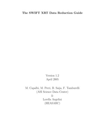
Swift XRT software Guide4 Circle (576, 20,44) Cal 3i.e., calibration source 0 is at location (DETX, DETY) (35,570) and has a radius of 47 pixels.2.2Description of XRT ModesThe XRT can operate in two states: Auto and Manual state. The Manual state is used forcalibration and the science modes can be commanded for a given observation. In Auto state theXRT automatically select the science mode according to the source count rate. The Auto state isthe normal operating mode.The XRT can operate in the following science modes in either Auto or Manual state: Image Long and Short (IM) Low rate (LR) and Piled-up Photodiode (PU) Windowed Timing (WT) Photon Counting (PC)In Auto state, the sequence in which the modes are scheduled on board and the exposure timedepend on the source brightness. Several parameters can be set for each of the modes and havebeen optimized since the beginning of the mission and they are listed at the end of this chapter. ThePhotodiode and Windowed Timing modes are also referenced within this guide as “Timing modes”.The Swift observatory has two main observation types Automatic Target (AT), when a new GRB isdetected and the satellite autonomously slews to the new position and Pre-Planned Target (PPT),when the observation is planned on ground and up-loaded to Swift. When observing a new GRB(AT) the XRT automatically schedules the different modes as shown in Figure 1. First it takesan image in Image mode to calculate the on-board source position and after run in sequence thefollowing modes: Photodiode, Windowed Timing and Photon Counting, switching automaticallybetween modes according with the source intensity. For PPT the same sequence is followed withthe exception that the Image mode is not scheduled. When the spacecraft settle on the AT, the firstdata taken are analysed on-board and the results are sent to the ground via TDRSS as messages anddistributed via the GCN. The content of these messages are described in the Chapter 7. Data froman Automatic or Pre-Planned Target observation are transmitted to the ground via the Malindistation.The following sections describe the characteristics of the individual modes. A short summary isgiven in table 2.1 together with the flux level at which the XRT switches between modes.In general, all modes are operated in high gain from the amplifier 1 except for imaging modewhich requires a larger full scale response for the brighest burst and therefore is read out fromamplifier 2 and in low gain.2.2.1Photodiode modesThe Photodiode mode is designed for very bright sources and for high time resolution. This modeperforms one serial clock shift and one parallel clock shift alternately and the result is a very rapidclocking of each pixel across any given point on the CCD. The charge is accumulated in the serialregister during each parallel transfer, with the result that each pixel contains charge integrated overthe entire field of view but not from the same instant in time. The stream of data is telemetered
5Swift XRT software GuideFigure 2.1: Sequence of the XRT mode for an Automatic TargetModePU & esYesYesNoNoTimeresolution0.14 ms1.7 ms2.5 s0.1 s (short)2.5 s (long)Cal sourcesin FOVyesnoSee window sizeyesOn-board Eventreconstructionno, done on-groundno, done on groundyesnot applicableFlux levelmode switch0.6-60 Crab1-600 mCrab 1 mCrab 140 mCrab 5.6 mCrabTable 2.1: Summary of the XRT mode characteristics. Note: the * indicates that in Piled-up modethe spectral capability is limited because if the source flux is too high the spectrum is piled-up .in ’pseudo-frames’ consisting of events from N rows and 602 pixels, where N is a commandableparameter. This mode is used when the image is dominated by a bright GRB or a very strongsource. Photodiode mode thus does not have spatial information but does produce a high resolutionlightcurve and a spectrum.The data are telemetered in two different ways : Low rate and Piled-up. In the Low rate modeonly pixels above the lower level discriminator threshold are sent down, whereas in the Piled-upmode all pixels in the ’pseudo-frame’ are sent down resulting in a more efficent telemetry format.The on-board software can be set to either subtract the bias on-board before sending down
Swift XRT software Guide6the data (default), or to send down the data without bias subtraction. In Piled-up mode the biascalculated in the last Low-rate frame is used for the bias subtraction. In Low-rate the bias is recalculated every frame. The timing information is inserted into every frame of the telemetry stream.The time tag for each pixel is performed on the ground and requires the frame start time and theknowledge of the source location on the CCD.The algorithm used to time tag the events assumes that the field of view is dominated by a singlebright source and the approximation used is that every photon arrives on the CCD at the sourceposition.The first 1850 pixels in the first frame taken in Photodiode mode are not fully exposed due tothe fact that there is a time delay before all pixels in the serial register have constant sky andbackground exposure. These partially exposed pixels are removed by the ground software.Typically, in a CCD detector the charge cloud produced by an X-ray photon is not localized intoone pixel but it is spread out over several pixels. The event reconstruction is not done on-boardand therefore the telemetry does not include for each event the neighborhood matrix. The eventreconstruction is performed on the ground, where pixels are evaluated to determine if the chargein the pixel is due to the main X-ray event or its diffusion. This process assigns the grade and thePHA value for each valid event.In Photodiode mode the signals from calibration sources are mixed with the data and this has tobe taken into account during spectral fitting by using an appropriate background spectrum. Sincethere is no imaging information in this mode, hot and flickering pixels can not be removed, but theimpact is minimal due to the clocking speed in this mode. The time resolution of this mode is 0.14ms. These modes are useful for fluxes up to 60 Crab and typically scheduled at the beginning ofobservation of a new GRB when the flux is high. Also data during the slews are collected in LowRate Photodiode.The initial data processing for the Photodiode mode has to account for the following : Remove partially exposed pixels Assign the proper arrival time to each event Subtract the bias only if the instrument is not configured to subtract the bias or insufficentbias has been sutracted. This is expected to occur sporadically. Reconstruct events and assign grade and PHA values. NOTE: During the data reduction ofthe Low-rate the split threshold can never be set less than the on-board lower level discriminator.2.2.2Windowed Timing modeThe Windowed Timing mode is obtained by binning 10 rows in the serial register, i.e. compressing10 rows into a single row, and then reading out only the central 200 columns of the CCD. Ittherefore covers the central 8 arcmin of the field of view and one dimensional imaging is preserved.The telemetered information is divided into frames, where each frame contains 600 rows. Similarlyto the Photodiode mode, the timing information is inserted every ’pseudo’ frame of 600 rows inthe telemetry stream and the time tagging of each pixel is performed on the ground. The pixelsin the first [60 0.5*(600/10)] rows are under exposed and removed during the data reduction.This requires the knowledge of the frame time and of the source position in detector coordinates.The Windowed Timing data are bias-subtracted on-board, and only pixels above the lower leveldiscriminator threshold are telemetered.
Swift XRT software Guide7Because the window setting includes only the central 200 columns, the calibration sources arenot included. Event reconstruction is performed on the ground where grade and PHA values areassigned. Bad columns can be removed corresponding to one image dimension, but due to thefast clocking the charge accumulated from bad and hot pixels is usually below the lower leveldiscriminator. The time resolution of this mode is 1.7 ms. This mode is useful for fluxes between1-600 mCrab. The initial data processing for the Windowed Timing has to account for the following: Remove partially exposed pixels Assign the time to each event Reconstruct events and assign grade and PHA. NOTE: During the data reduction of theWindowed Timing the split threshold can never be set less than the on-board lower leveldiscriminator. Flag bad columns2.2.3Photon Counting modePhoton counting mode retains full imaging and spectroscopic resolution but the time resolution islimited. A full field of view is accumulated every 2.5 sec and the CCD operates in what is knownas ‘frame-transfer’ configuration. Each CCD frame is rapidly transferred into a framestore area,and then read out by clocking the frame store one row at a time into the serial register. The pixelsare processed on board where the bias is subtracted, the lower level discriminator is applied andthe events are reconstructed. The latter is done by testing if the central pixel of a 3x3 matrix isthe local maximum and whether or not it falls between the event discriminator and upper leveldiscriminator thresholds. Then the outer guard ring pixels (a 5x5 matrix) are tested to check ifany exceeds the outer ring threshold. This eliminates most of the cosmic rays and chip defects.For each valid event, the 3x3 matrix is telemetered. On the ground a single PHA value is reconstructed and the grade assigned according to the grade description given in the following sections.The calibration sources are included in the data when the window is set to the full field of view600x600 pixels and these are removed on the ground when screening the data. During operation formost of the time the standard window setting is smaller (480x480 pixels) excluding the calibrationsources and only a few frames for engineering purposes are taken with the full field of view eachday. The time resolution of this mode is 2.5 seconds. This mode is useful for fluxes below 1 mCraband is piled-up if there is more than 2 source count per frame.The initial data processing for the Photon Counting mode has to do for the following : Flag bad pixels (as defined in CALDB) Flag thresholded events Flag calibration sources Calculate and Flag hot and flickering pixels Assign grade and PHA values
Swift XRT software Guide2.2.48Image modeImage mode is used by the XRT to obtain a rapid position of a new GRB. If the spacecraft slews toa new GRB, the XRT takes an image and processes the image on-board to determine its position.The CCD operates like an optical CCD, collecting the accumulated charge on the detector andreading out without any X-ray event recognition. The image will be highly piled-up and producesno spectroscopy data, but it is used to derive accurate position and flux estimates. The Imagemode operates in low gain and can be used for fluxes between 25 mCrab and 45 Crab. Due to howthe Image mode operate, the image is not a 2D histogram of the number of events but each pixelcontains a DN (DN Data Number, the native units for the amplifier’s analog-to-digital converter)value proportional to the total charge accumulated in that pixel during an exposure.Only pixels exceeding the lower level discriminator threshold are sent down. The detector bias isnot subtracted on-board and also the calibration sources maybe included depending on the windowsetting. Depending on the source flux the exposure of image mode is automatically set on-boardeither to 0.1 or 2.5 seconds.The initial data processing for the Imaging mode has to do the following: Subtract the bias Clean calibration sources Clean bad pixels2.3Classification of Events and GradeTo eliminate events due to charged particles and to obtain the expected energy resolution, Xray events from each readout are identified and classified. For the Photon Counting mode thedistribution of the charge in the 3x3 matrix is classified according to a library of 32 grades (See fig.2.2). For the Photon counting mode, grades in the range of 0-12 are considered good grades.For Windowed Timing and Photodiode modes, it is not possible to use the above grade definitionsince the 3x3 matrix information is not available. A 7x1 matrix is instead used to reconstruct theevents and
The data reduction procedure for the Swift XRT uses tools that account for the calibration, as-pect and algorithms specific to the XRT (XRTDAS) as well as generic tools, FTOOLs, used to manipulate the FITS data files. The main focus of this Guide is on : Swift XRT data files, the properties of the Swift XRT instrument and its modes, and