Transcription
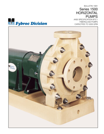
BULLETIN 15B1Series 1500HORIZONTALPUMPSFybroc DivisionANSI SPECIFICATION B73.1FIBERGLASS PUMPSCAPACITIES TO 5200 GPM
Fybroc–the leader in corrosion-resistantfiberglass pumping equipmentFybroc is an advanced technology pump manufacturer specializing in reinforced composite centrifugalpumps, designed to handle corrosive liquids.Fybroc, the pioneer in the fiberglass pump field,continues its position of leadership with its Series1500 pump. This line is the culmination of many yearsof experience in producing high quality, corrosionresistant pumps.2The Series 1500 combines an extensive knowledge ofmaterials and production techniques to provide exceptionalstructural integrity, excellent corrosion resistance, anddependable service in difficult operating environments.
Materials of construction are available for awide range of corrosive liquidsOnly Fybroc has the flexibility in materials selection tosolve your difficult corrosive or abrasive pump problems.Fybroc's standard vinyl ester resin, VR-1, handles thevast majority of corrosive applications. This premiumquality resin offers broad corrosion-resistance to mostacids, caustics, bleaches, sea water and other liquids.Fybroc’s epoxy resin, EY-2, offers outstanding solventresistance and is available in many pump sizes fordifficult organic applications.Fybroc’s VR-1V material provides a protectivesynthetic veil barrier on applications such as hydrofluoricacid which would attack the fiberglass reinforcement of anormally constructed pump.Fybroc can also provide an FDA-approved vinyl esterresin for use on acids, brines or caustics in food processing plants.For further information on corrosion resistance tospecific chemicals, refer to Bulletin MS101, ChemicalResistance Guide, or contact your Fybroc distributor.Fybroc offers VR-1A for highly abrasive services suchas titanium dioxide or fly ash.Fybroc Series 1500 Resin TransferMolded parts provide superior strengthThe fiberglass components in the Series 1500 pumpsare produced using a Resin Transfer Molding (RTM)process which allows for the controlled placement of fiberglass reinforcement in high stress areas. This techniqueresults in a finished product with superior strength.benefit from the reinforcing properties of the RTMprocess. This permits the handling of normal pipe loadsunder full working pressures. This method of reinforcement in the impeller extends the life of this componentand provides unparalleled strength without degradationin corrosive environments.Critical components such as the single-piece casing,with its heavily gusseted suction and discharge flanges,Corrosion-resistant fiberglass baseplatesFybroc manufactures fiberglass baseplates becausechemical pumps are used in environments where external corrosion can be a serious problem. These corrosion-resistant, fiberglass reinforced vinyl ester resinbaseplates come in eight sizes and meet ANSI outlineand mounting dimensions. Seven baseplates feature acenter collecting drain with tapped outlet connectionand provision for a grouted foundation. The Model #4baseplate can be adapted for use with ANSI or otherhorizontal pumps. Modified baseplates are availablefor stilt-mounting. Refer to page 13 for additionalbaseplate information and specifications.3
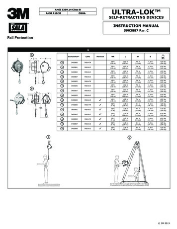
Design features of theSeries 1500 PumpThe Fybroc Series 1500 pump is designed for broadcorrosion-resistance through the use of high qualitymaterials and state-of-the-art engineering. Its simplicityand versatility make it the ideal choice for all toughpumping requirements.1213The fiberglass components are manufactured utilizingthe Resin Transfer Molding technique which enablescomplete control of the fiberglass reinforcement in highstress areas. Metallic pump components are not incontact with pumped fluids.14111049
1. ANSI B73.1 CONFORMANCE ensuresinterchangeability with existing metalANSI pumps, eliminating any need forpiping or foundation changes when upgrading an installation to Fybroc Series1500 pumps.12. SMOOTH HYDRAULIC PASSAGESpromote increased pump efficiency.23. SINGLE PIECE GUSSETED CASINGeasily withstands the rigors of plantpiping loads.34. IMPELLER PUMPOUT VANES andre-lief holes reduce axial thrust andstuffing box pressure.45. ALLOY INSERT with rounded edgescarries impeller torque loads withlow stress.56. VERSATILE CASING COVER permitsthe use of a large number of mechanicalseals or packing for specific applications; see page 7 for some of the mostfrequently used configurations andpage 8 for seal flush considerations.7. FIBERGLASS CONSTRUCTION for allwetted parts in either vinyl ester orepoxy resin provides tough corrosionresistance for a wide range of difficultliquids.68. CASING THROUGH-BOLTS maintaincasing O-ring seal integrity under allhydraulic operating conditions.79. INTEGRAL SHAFT SLEEVE designeliminates gaskets and O-rings.10. LARGE-CAPACITY BEARINGS ensureoperating life well in excess of theminimum specified by ANSI B73.1.811. EXTERNAL IMPELLER ADJUSTMENTallows field setting of impeller-to-casingclearance.12. HEAVY-DUTY SHAFT minimizes deflection to maximize mechanical seal life.13. EPOXY-COATED POWER FRAMEcomponents prevent external corrosion.14. LABYRINTH OIL SEALS nickel platedbronze for longer life. Improved oilcontainment.5
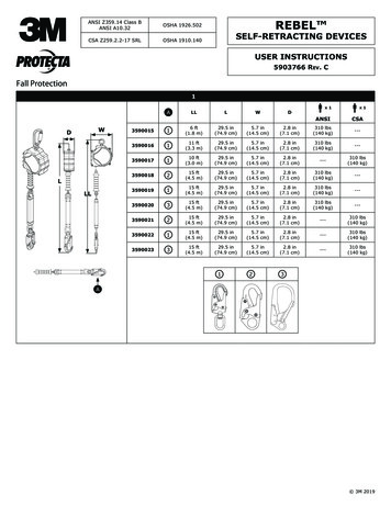
Design provides formaximum seal andbearing lifeThe Series 1500 pumps have been designed tomaximize the life of bearings and mechanical sealswhich can deteriorate because of shaft deflection resulting from radial thrust. Radial thrust is the force acting onthe side of an impeller as a result of the non-uniformdistribution of pressure around the pump casing atoff-peak operation.The magnitude of this thrust varies with the flow, butthe amount of radial thrust can roughly be cut in half byutilizing a double volute casing. The solid line in the chartto the right depicts the typical radial thrust characteristicof a single volute casing. The dotted line portrays the useof a double volute casing and the resulting reductionin radial thrust.CutwaterThe drawing at lower right shows the location of the“cutwater” in volute casings. The cutwater is the closeclearance extension of the casing located at the base ofthe volute. Also, shown in orange, is the second cutwateror “splitter” used in the double volute casing, whichchannels half of the flow to the pump discharge. Thesplitter reduces the pressure imbalance in the casingduring off-peak flows and reduces both radial thrust andits resulting shaft deflection. Fybroc uses double volutecasings in ten of its larger pump sizes where radial thrustloads are high: the 3 x 4 x 8, 11/2 x 3 x 10, 2 x 3 x 10,3 x 4 x 10, 4 x 4 x 10, 2 x 3 x 13, 3 x 4 x 13, 4 x 6 x 13, 6 x 8 x 13,8 x 10 x 13, 8 x 10 x 15 and 10 x 12 x 16.SplitterMaterials of constructionCOMPONENTVINYL ESTER PUMPEPOXY Y-2GlandVR-1EY-2Shaft303-Stainless Steel303 Stainless SteelBearing Hsg.Epoxy-Coated IronEpoxy-Coated IronAdapterEpoxy-Coated IronEpoxy-Coated IronHardware303 Stainless Steel303 Stainless-SteelO-RingsViton AViton A* VR-1 Fiberglass Reinforced Vinyl Ester6**EY-2 Fiberglass Reinforced Epoxy†Not available in all sizes, contact Fybroc for availability.
Mechanical seal arrangementsFybroc 1500 pumps are available with a wide variety ofmechanical seals or stuffing box packing. For corrosivefluid handling, single outside and double inside seals arerecommended. The single outside seals have non-metallicwetted parts and all metal components located outsidethe pump. The double inside mechanical seals have metalparts that are exposed to buffer fluid only and at no timeexpose the pumped fluid to metallic components.The following illustrations outline some commonly usedsealing arrangements. Your Fybroc distributor can supplyadditional information on other available seals. See page 8for seal flush considerations.Crane Double 8DDurametallic RXOCrane Type 8-1-TCrane Type 20RCrane Type 8B2Packed Box7
Seal flushingarrangementsAll mechanical seals require flushing to lubricate theseal faces and maintain normal operating temperatures.Seals are normally flushed with a clean external fluid or,if possible, by the liquid being pumped. Fybroc Series1500 pumps are furnished as standard with tapped glandsfor connection to the flush liquid or with the optionalconfigurations shown below.Internal seal flushLOWPRESSURELIQUIDFybroc’s Internal Cover Flush option eliminates theneed for external flush of single mechanical seals fromthe pump discharge, which also eliminates the possiblebreakage of tubing and fittings.This option removes seal heat by circulating high pressure liquid internally through the drilled cover to the sealchamber and then recirculating this liquid back to the lowpressure side of the pump.Fybroc TEFC Gland air-cooledsealing systemDouble mechanical seals normally require external flushliquid. The Fybroc TEFC Gland eliminates the need forexternal flush and increases the life of the seal bysubstantially improving its operating environment. Inaddition to these cost-saving benefits, the TEFC Glandalso permits the pump to be run dry in the event thatliquid flow to the pump is accidentally lost.The Fybroc TEFC Gland air-cooled sealing systemconsists of a Hastelloy C finned gland containing a doublemechanical seal. A shaft-mounted fan circulates air overthe gland fins, removing the heat generated by the seal.The seal coolant liquid is mechanically circulated to areservoir mounted on the pump, where the system ispressurized by compressed air or bottled nitrogen. Liquidlevel in the reservoir can be visually monitored. A levelswitch mounted in the reservoir can be used to eithersound an alarm or shut down the pump in the event oflow coolant level.HIGH PRESSURELIQUIDCompressed AirConnectionReservoirGlandFan8
Engineering information–Series 1500IMPELLERCLEARANCESHAFT AND BEARING DATA6 x 8 x 138 x 10 x 1510 x 12 x 163/ 164 x 6 x 1313 x 4 x 135/ 85/ 162 x 3 x 13A50A60A70-A80A30A40A80A90A120-5/ 83/ 415/ 161/ 211 1/ 81 3/ 41 3/ 83/ 8FRONT.015.020.025BACK.045.040.035CASINGTHICKNESS .251.37DOUBLEDIA. AT IMPELLER3/ 41 1/ 41 1/ 2DIA. UNDER SLEEVE1 1/ 81 3/ 42 1/ 21.38 / 1.381.97/ 1.772.76/ 2.761 5/ 82 1/ 43 1/ 4BEARING SPAN3.797.0910.25DIA. AT COUPLING7/ 811/ 82 3/ 8BEARING NO.INBOARD307MZC3310MZC36314ZC3BEARING NO.OUTBOARD5207AZC35309EZC35314EC3SHAFT HP PER100 RPM1.14414.8DIA. AT BEARINGSIB/OBDIA. BETWEENBEARINGSL’10 LIFEBOX DATAA054 x 6 x 101/ 2A704 x 4 x 103/ 8A603 x 4 x 10MAX. SPHERE SIZEA502 x 3 x 10AA1.5 x 3 x 10-1 x 2 x 101 x 1.5 x 8AB3x4x82x3x6AA2x3x81.5 x 3 x 6ANSI DESIGNATIONCASING DATA1 x 1.5 x 6DISCHARGEXSUCTIONXPUMP IMPELLER DIA.1.5 x 3 x 8DIMENSIONS SHOWN IN INCHESMINIMUM 3 YEARSBEARING FRAMEGROUPIIIIIIOIL CAPACITY(PINTS)3/ 42 1/ 26SLEEVE (O.D.)1 3/ 82 1/ 82 7/ 8STUFFING BOXBORE2.002.883.75MAX DEPTH OF BOX2.753.253.50PACKING SIZEDIST. TO FIRSTOBSTRUCTION5/ 16x 5/ 163.143/ 8x 3/ 83.987/ 16x 7/ 164.879
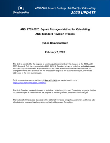
Fybroc Series 1500–the industry’s most extensivefiberglass corrosion-resistant coverage15035302520TOTAL HEAD IN METERS60 HERTZ10080156050401030TOTAL HEAD IN FEET1150 102x3x10 x4x811/2x3x61x11/2x61150RPM2x3x62U.S. GALLONS PER MINUTE50201015325030100 150 200 300200060 80 100 150 200 30030 4015 201010005004000 6000500 700 1000 150060 HERTZ706050403025201510250200150TOTAL HEAD IN FEET1750 RPMTOTAL HEAD IN METERSCUBIC METERS PER 06x8x134x6x132x3x101x11/2x83x4x10 1/2x652x3x6U.S. GALLONS PER MINUTE100201012100 150 200 3005030531015 2030 4010005004000 6000200060 80 100 150 200 300500 700 1000 1500CUBIC METERS PER HOUR150120100TOTAL HEAD IN METERS60 HERTZ8060506005004001x2x10300TOTAL HEAD IN FEET3500 .S. GALLONS PER MINUTE501102203530 40 501010015 20CUBIC METERS PER HOUR102x3x84x4x1020NOTE: For specificperformance curves refer tocurve book.3x4x10150 20030 4030050060 80 1001000150 2003002000
5040206050401510830252061537250 x811/2x3x81x11/2x66x8x133x4x10 4x4x102x3x811/2x3x64101450 RPM8x10x1530TOTAL HEAD IN METERSTOTAL HEAD IN FEET150120100804x6x103x4x81450RPM2x3x6CUBIC METERS PER HOUR10325108 106415 2030 4030 4015 20100 150 200 3006060 80 100 150 200 300 400 6001000500 700 10002000 30005000U.S. GALLONS PER MINUTE5001502900 RPM3002501002006050 HERTZ801x2x10TOTAL HEAD IN METERSTOTAL HEAD IN 82x3x61030258202900RPM615410CUBIC METERS PER HOUR3021510415 2068 1030 4015 2060 80 10060 80 10030 40150 200300 400150 2006003001000 1500U.S. GALLONS PER MINUTEPressure–temperature ratingsShaft horsepower (KW) limits* STANDARD 150 POUND FLANGESNOTE: Refer to Corrosion Guide for specificapplication ratings.250RPM16501350KILOPASCAL — kPa1050 1501257501006004503002900175014501150Group I40 HP(30 KW)33 HP(25 KW)20 HP(15 KW)17 HP(12 KW)13 HP(9.8 KW)Group II140 HP(104 KW)116 HP(88KW)70 HP(52 KW)58 HP(43 KW)46 HP(34 KW)Group III——260 HP(194 KW)215 HP(160 KW)170 HP(127 KW)2001200 1759003500GROUP II*75MAXIMUM WORKING PRESSURE — PSI1500225GROUP IGROUP III (Except 10x12x16)* 1150 RMP maximum for 10 x 12 x1610x12x165015025000-18 -1025050TEMPERATURE - F75 100 125 15017520022525010 20 30 40 50 60 70 80 90 100 110 120TEMPERATURE - C11
Pump dimensions for Series 1500CPYVXUHDE1FE21.5 x 3 x 82x3x83x4x81 x 2 x 101.5 x 3 x 102 x 3 x 103 x 4 x 104 x 4 x 104 x 6 x 102 x 3 x 133 x 4 x 134 x 6 x 13—AAA50A60A70A05A50A60A70—A80A30A40A80A90 A100 A120 —CP171/ 2445231/ 2597D51/ 4133X61/ 2165F71/ 4184121/ 2318183/ 4476173/ 4541**2E1615293/ 424816406225592E20071/ 41849229143565/ 87/ 8162212581/ 421081/ 2216H91/ 22421128081/ 22167/ 8U22.231025491/ 224211 121/ 2 131/ 2 111/ 2 121/ 2 131/ 2 16280
1. ANSI B73.1 CONFORMANCE ensures interchangeability with existing metal ANSI pumps, eliminating any need for piping or foundation changes when up-grading an installation to Fybroc Series 1500 pumps. 2. SMOOTH HYDRAULIC PASSAGES promote increased pump efficiency. 3. SINGLE PIECE GUSSETED CASING easily withstands the rigors of plant piping loads. 4. IMPELLER PUMPOUT