Transcription
Citrix XenServer 7.1 vSwitch Controller User GuidePublished November 20181.0 Edition
Citrix XenServer 7.1 vSwitch Controller User GuideCopyright 2018 Citrix Systems. Inc. All Rights Reserved.Version: 7.1Citrix, Inc.851 West Cypress Creek RoadFort Lauderdale, FL 33309United States of AmericaDisclaimersThis document is furnished "AS IS." Citrix, Inc. disclaims all warranties regarding the contents of this document,including, but not limited to, implied warranties of merchantability and fitness for any particular purpose. Thisdocument may contain technical or other inaccuracies or typographical errors. Citrix, Inc. reserves the right torevise the information in this document at any time without notice. This document and the software describedin this document constitute confidential information of Citrix, Inc. and its licensors, and are furnished under alicense from Citrix, Inc.Citrix, the Citrix logo, Citrix XenServer and Citrix XenCenter, and other trademarks appearing herein are theproperty of Citrix Systems, Inc, or one or more of its subsidiaries, and may be registered in the United StatesPatent and Trademark Office and in other countries. All other trademarks and registered trademarks are propertyof their respective owners.TrademarksCitrix XenServer XenCenter This product contains an embodiment of the following patent pending intellectual property of Citrix Systems, Inc.:1. United States Non-Provisional Utility Patent Application Serial Number 11/487,945, filed on July 17, 2006,and entitled “Using Writable Page Tables for Memory Address Translation in a Hypervisor Environment”.2. United States Non-Provisional Utility Patent Application Serial Number 11/879,338, filed on July 17, 2007,and entitled “Tracking Current Time on Multiprocessor Hosts and Virtual Machines”.
Contents1. Introduction . 11.1. vSwitch and Controller for XenServer . 12. Getting Started . 22.1. Deploying the vSwitch Controller Virtual Appliance . 22.2. Accessing the vSwitch Controller Command Line Interface . 32.3. Accessing the vSwitch Controller Graphical User Interface . 32.3.1. Accessing the vSwitch Controller GUI Remotely . 32.4. Configuring the vSwitch Controller IP Address . 32.5. Adding Resource Pools . 42.6. Configuring High Availability . 43. vSwitch Management . 53.1. Interface Overview . 53.1.1. Top Panel . 53.1.2. Status Bar . 53.1.3. Top Icons . 63.1.4. Side Panel . 63.1.5. Using the Resource Tree . 63.1.5.1. Color-Coded Icons . 73.1.6. Main Panel Data Area . 73.2. Using the Dashboard to Monitor Network Activity . 83.2.1. Server Statistics . 83.2.2. Network Statistics . 83.2.3. Recent Network Events . 83.2.4. Recent Administrative Events . 83.2.5. Throughput, Flows, and Bit Rate Graphs . 94. Virtual Network Visibility & Control . 104.1. Viewing Status . 104.1.1. Global Level . 10iii
4.1.2. Resource Pool Level . 104.1.2.1. Fail safe mode . 114.1.3. Server Level . 114.1.4. Network Level . 124.1.5. Virtual Machine (VM) Level . 124.1.6. Virtual Interface (VIF) Level . 134.1.7. Viewing Flow Statistics . 134.2. Managing Address Groups . 154.3. Managing Virtual Machine Groups . 154.4. DVS Policy Configuration Hierarchy . 164.5. Setting Up Access Control Policies . 164.5.1. Global Access Control List (ACL) Rules . 174.5.2. Resource Pool Access Control List (ACL) Rules . 174.5.3. Network Access Control List (ACL) Rules . 174.5.4. VM Access Control List (ACL) Rules . 174.5.5. VIF Access Control List (ACL) Rules . 174.5.6. Access Control List (ACL) Rule Enforcement Order . 184.5.7. Defining Access Control List (ACL) Rules . 184.6. Setting Up Port Configuration Policies . 204.6.Configuring QoS. Configuring QoS . 214.6.2. Configuring RSPAN . 224.6.2.1. Identify your RSPAN VLAN . 224.6.2.2. Configure the Physical Network with the Target VLAN . 224.6.2.3. Configure vSwitch Controller with the Target VLAN . 224.6.2.4. Modify port configuration to enable RSPAN for a set of VIFs . 234.6.2.5. Configuring MAC Address Spoof Checking . 234.6.2.6. Save Changes . 235. vSwitch Controller Administration & Maintenance . 245.1. Configuring IP Address Settings . 245.2. Configuring the Controller Hostname . 255.3. Collecting Information for Trouble Reports . 25iv
5.4. Restarting the vSwitch Controller Software . 255.5. Managing Administrative Accounts . 255.6. Managing Configuration Snapshots . 265.7. Adding Network Time Protocol (NTP) Servers . 265.8. Exporting Syslog Files . 276. Troubleshooting vSwitch Controller Issues . 286.1. Resource Tree Node Status . 286.2. Troubleshooting Access Policy Issues . 296.3. Creating a Trouble Report . 296.4. Controller Error Messages . 307. Command Line Interface . 317.1. CLI Commands . 317.1.1. To terminate the current CLI session . 317.1.2. To halt the vSwitch Controller . 317.1.3. To get information on commands . 317.1.4. To upgrade or downgrade the existing version of the Controller . 317.1.5. To ping a specified remote system . 317.1.6. To restart the Controller . 317.1.7. To restart the Controller daemon . 327.1.8. To set the hostname of the controller appliance . 327.1.9. To set the IP address of the Controller management interface via DHCP . 327.1.10. To set a static IP address for the Controller management interface . 327.1.11. To display the current Controller hostname . 327.1.12. To display a summary of the current configuration and status of themanagement interface . 327.1.13. To display configuration values for the management interface . 327.1.14. To display the current default gateway for the Controller . 327.1.15. To display the current DNS configuration for the Controller . 337.1.16. To display the current IP address of the Controller management interface . 337.1.17. To display the current netmask of the Controller management interface . 337.1.18. To display the software version of the Controller . 33v
Chapter 1. IntroductionThe XenServer platform is a server virtualization platform for server and client operating systems that virtualizeseach physical host on which it is installed, enabling a single physical machine to run multiple virtual machines(VMs) simultaneously.XenServer allows you to combine multiple XenServer hosts into a resource pool, using industry-standard sharedstorage architectures and Citrix resource clustering technology. Resource pooling extends the basic single-servernotion of virtualization to multiple servers, with VMs able to run on any server in the pool and even move betweendifferent servers in the pool using a technology called live migration. Each resource pool includes a master server,which stores configuration for all physical hosts and VMs in the pool.XenCenter is a Windows-based management application that allows IT managers to create XenServer resourcepools and to manage them and their resources from a single point of control. XenCenter provides a graphicalinterface to perform many of the same VM, storage, and clustering configuration operations that can beperformed using the “xe” utility on the XenServer command line.1.1. vSwitch and Controller for XenServerThe vSwitch brings visibility, security, and control to XenServer virtualized network environments. It consists ofa virtualization-aware switch (the vSwitch) running on each XenServer and the vSwitch Controller, a centralizedserver that manages and coordinates the behavior of each individual vSwitch to provide the appearance of asingle vSwitch.The vSwitch Controller supports fine-grained security policies to control the flow of traffic sent to and from aVM and provides detailed visibility into the behavior and performance of all traffic sent in the virtual networkenvironment. A vSwitch greatly simplifies IT administration within virtualized networking environments, as all VMconfiguration and statistics remain bound to the VM even if it migrates from one physical host in the resourcepool to another.1
Chapter 2. Getting StartedThis chapter describes how to get started using the vSwitch Controller. Refer to the Release Notes for instructionson enabling the DVS vSwitch on the XenServers of a resource pool. The information in this chapter assumesthat you have at least one XenServer resource pool configured in XenCenter and that you have sufficientcapacity within that pool to deploy the vSwitch Controller virtual appliance VM. The requirements for controllerdeployment are described in the next section.Setting up the vSwitch Controller involves the following tasks:1. Deploying the vSwitch Controller Virtual Appliance2. Accessing the vSwitch Controller3. Configuring the Controller IP Address4. Adding Resource Pools5. Configuring High-Availability (optional)Note:This version of vSwitch Controller supports the following XenServer versions: 7.1, 7.0, 6.5.0,6.2.0, 6.1.0, and 6.0.2.1. Deploying the vSwitch Controller Virtual ApplianceThe XenServer that runs the vSwitch Controller must meet the following minimum requirements: 2 CPUs 2GB DRAM 16GB DiskThe minimum allowed VM configuration for the vSwitch Controller appliance and the default configuration onimport is: 2 vCPUs 2GB DRAM 16GB DiskThis configuration will support deployments up to 16 XenServers and 256 Virtual Interfaces (vifs) connected tothe vSwitch Controller. For larger deployments (up to the maximum supported limit of 64 XenServers and 1024vifs), the VM configuration should be modified to: 4 vCPUs 4GB DRAM 16GB DiskThe vSwitch Controller VM may run within a resource pool that it manages. Generally, this configuration runs asif the vSwitch Controller VM was running separately. However, it may take slightly longer (up to 2 minutes) toconnect all the vSwitches in the event of a Controller migration or restart. This is due to differences in how theindividual vSwitches route control connections.To install the vSwitch Controller, import the supplied virtual appliance VM image into a XenServer resource pool.During import, attach the single VIF of the imported VM to a network through which the XenServer or XenServerpool to be controlled by the VM is reachable. Refer to the XenServer documentation for more information.Note:2
If you are using XenServer 7.1 with Cumulative Update 2 or later applied, ensure thatyou update your vSwitch Controller virtual appliance to the latest version provided on theXenServer Product Download page for XenServer 7.1 Cumulative Update 2. This version of thevSwitch Controller virtual appliance is the same as the version provided for XenServer 7.6 CR.After the VM has been imported, start it to begin the process of configuring the DVS.2.2. Accessing the vSwitch Controller Command Line InterfaceYou can access the vSwitch Controller command line interface (CLI) from within XenCenter or remotely using anSSH client. When the vSwitch Controller VM first boots, the text console within XenCenter will display a messageindicating the IP address that can be used to access the controller remotely. If the VM did not receive an IPaddress, the text console will indicate that an address must be assigned through the CLI. In either case, the textconsole will display a login prompt to log into the CLI locally in the XenCenter console. Full documentation of theavailable CLI commands is included in Chapter 7.2.3. Accessing the vSwitch Controller Graphical User InterfaceYou can access the vSwitch Controller graphical user interface (GUI) remotely using a web browser. When thevSwitch Controller VM boots, the text console within XenCenter will display a message indicating the IP addressthat can be used to access the GUI remotely. If the VM did not receive an IP address, the GUI can not be usedlocally or remotely until one is assigned. The text console will provide instructions on setting the IP address locallyin the command line interface. Once the controller VM has the IP address, the GUI can be accessed locally withinthe XenCenter console by following the steps in the next section.Note:Since VNC is disabled, vSwitch Controller GUI can be accessed only from a web browser.2.3.1. Accessing the vSwitch Controller GUI RemotelyTo access the vSwitch Controller interface remotely:1. Open a browser and enter the following URL, where server is the IP address or host name of the interfaceof the controller VM: https://server:8080/2. Enter your user name and password, and click Login. The default user name and password are admin andadmin.Note:By default, the vSwitch Controller webserver uses a self-signed certificate, which will causemany browsers to show a security error when connecting to the GUI. You can safely ignorethe error and install the certificate into your browser.The following browsers are supported: Firefox 3.x, Safari 4.x, Internet Explorer 7 and 8. Othermodern browsers of similar capability (such as Opera or Google Chrome) are not supported,but may work as well. Internet Explorer 9 addresses known IE memory and resource leakissues; however it has not received full testing.When you log in for the first time, the system prompts you to change the default adminpassword. It is important that you create a strong admin password to protect the security ofyour virtualized infrastructure.2.4. Configuring the vSwitch Controller IP AddressWhen the vSwitch Controller is started for the first time, it attempts to obtain an IP address using DHCP; however,we recommend that you assign a static IP address. If DHCP is configured, resource pools cannot be set to FailSafe mode3
To assign a static IP address:1. Access the vSwitch Controller interface locally, as described in the previous section.2. Click the Settings tab and then IP Configuration in the side panel. The current settings are shown.3. Click Modify Configuration, specify the new IP address information, and click Make Changes.Note:If DHCP is configured, resource pools cannot be set to Fail-Safe Mode.2.5. Adding Resource PoolsAdding a resource pool allows the vSwitch Controller to automatically begin managing all XenServer hosts in thatpool.To add a resource pool:1. Under Visibility & Control, open the Status tab and choose All Resource Pools in the resource tree (sidepanel) to open the Status page for all resource pools.2. Click Add Resource Pool. An error message is displayed if you do not have the correct license to add anadditional resource pool.3. Enter the IP address or DNS name of the master XenServer in the Pool Master Server (DNS/IP) field.4. Enter the username and password for administrative access to the server.The user must have full management capabilities in the resource pool. The vSwitch Controller will not be ableto properly manage the pool if the account has restricted capabilities.Typically, this will be the user named "root" but could be a different name if the RBAC features of theXenServer platform are in use.5. Select the Steal check box only if you want to override any existing vSwitch Controller configuration that waspreviously set for this resource pool.6. Click Connect.The vSwitch Controller will use the provided username and password to communicate with the pool master serverusing the XAPI protocol. When communications are established, the new resource pool is added to the resourcetree, along with all of the associated resources. If the vSwitch Controller VM is unable to communicate with thepool master, it displays an error message describing the failure.Note:For the vSwitch Controller and the XenServer resource pool to communicate with each other,the XenServer resource pool must be using the Backwards compatibility mode (which is thedefault). You can specify this setting on the Pool Properties page in XenCenter. For moreinformation, see XenCenter Help.2.6. Configuring High AvailabilityTo ensure that XenServers can always reach an active vSwitch Controller, we recommend the use of Citrix HighAvailability for the vSwitch Controller VM. Refer to the XenServer Administrator's Guide for instructions onenabling high availability. Because continuous operation of the vSwitch Controller is critical to the operation ofnetworking for all virtual machines, the vSwitch Controller VM restart-priority should be set to 1 and ha-alwaysrun should be set to true.4
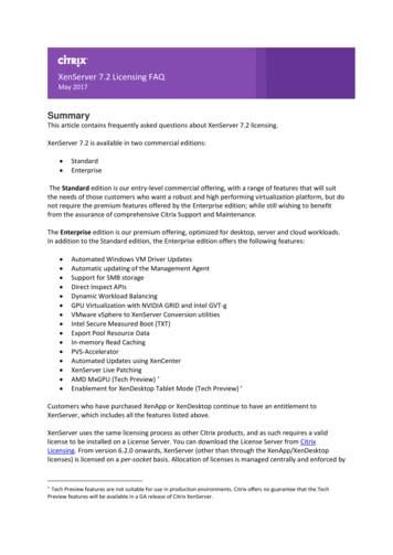
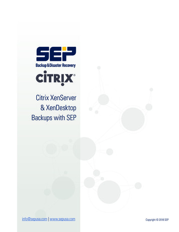
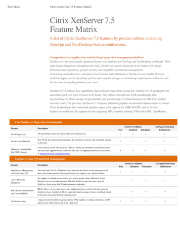
Chapter 3. vSwitch ManagementThe vSwitch Controller GUI allows you to view status and flow statistics for elements within the virtual network,set up VM access control, QoS, and traffic mirroring policies, and modify configuration of the vSwitch Controllervirtual appliance.3.1. Interface OverviewThe vSwitch Controller GUI is divided into the three different panels, as shown in the next figure.Figure 3.1.3.1.1. Top PanelThe top panel is always visible when using the GUI and includes a status bar and a set of main navigation icons.3.1.2. Status BarThe gray status bar at the top of the vSwitch Controller window contains the following information and functions(left to right): Version: Current vSwitch Controller version. Online Help: Click to display or close an online help area near the top of the controller window. Logout: Click to log out of the vSwitch Controller GUI. User: Displays the user name of the user that is currently logged in. Refresh icon: Click to manually update the information on the page. Play/Pause: Click to toggle whether the GUI should automatically refresh data on the screen using backgroundupdates. In play mode, the data that is shown refreshes automatically every 15 seconds. In pause mode,most data is not updated; however, a few elements are updated, notably the resource tree. The status bar5
background behind the buttons turns orange and a “Data Updates Paused” indicator appears in the statusbar when in pause mode.3.1.3. Top IconsClick the top icons to access the major functional areas within the GUI. Dashboard: View summary statistics and information about network and administrative events. SeeMonitoring Network Status with the Dashboard. Visibility and Control: View network status and statistics or configure access control, QoS and traffic mirroringpolicies for virtual networks. See Viewing and Controlling the Network. Settings: Perform vSwitch Controller maintenance and administrative functions. See Administering andMaintaining the vSwitch Controller.3.1.4. Side PanelThe side panel is available only in the Visibility and Control and Settings section.For the Visibility and Control section, the side panel contains a resource tree that you can use to browsenetwork elements within the virtual network environment. Similar to the resource tree in XenCenter, elementsare organized hierarchically and provide an easy way to browse elements within the system. To expand a sectionof the resource tree, click the side-facing arrow next to the node text. An expanded node is marked with a downfacing arrow, which you can click to collapse.When you select an element from the resource tree, the main panel displays status and configuration data forthat node in the tree. For example, if you select a VM from the resource tree and choose Status in the Visibilityand Control section, the main panel displays status information about the selected VM.The resource tree includes a search function. To filter the contents based on a search string, enter text in thesearch field, and press Enter. Click the X symbol to clear the search. Searches support wildcards (* for one ormore characters and ? for a single character). If wildcards are not used, the system performs a substring searchas if a * wildcard were entered at the start and end of the search string. For example, the search “Lab” finds allitems with “Lab” in the name, such as “Laboratory-1” and “New-Lab-5.”For the Settings section, the side panel contains icons to select which area of vSwitch Controller configurationthe user would like to view or modify3.1.5. Using the Resource TreeAt the highest level, the resource tree displays the following items: All Resource Pools: List of all the available resource pools. This is the top-level resource for exploring allXenServers, Networks, VMs, and VIFs that are part of each resource pool. Address Groups: Named sets of IP addresses and subnet ranges to be used to limit the application of a rulein the access control section or to limit the scope of a query in the Flow Statistics section. VM Groups: Named sets of VMs to be used to simplify viewing the status and flow statistics of a particularcollection of VMs.When you expand a resource pool in the resource tree, the following items are displayed: Pool-wide networks: This list includes all networks in the resource pool and is similar to the list in the Networktab of XenCenter. You can expand the list to show the individual networks, expand a network to show theVMs on that network, and expand a VM to show its VIFs on that network. XenServers. This list is similar to the server hierarchy in XenCenter. You can expand the list to show all of theservers in the pool and expand a single server entry to show the networks, VMs, and VIFs associated with theserver. The Server Networks listing is similar to what you see if you click a server in XenCenter and choosethe Network tab.6
All VMs: This list shows all VMs in the resource pool, whether or not they are configured for a single server.You can expand the list to show the individual VMs, and expand a VM to show its VIFs.Right-click context menus on nodes are available on most nodes to provide a simple way of adding, modifying,and deleting items in the resource tree.3.1.5.1. Color-Coded IconsColor-coded icons in the resource tree show the state of tree nodes under the top-level “All Resource Pools”node. Similar to XenCenter, these color codes are based on data retrieved via XAPI from each pool master. Whena node state changes, the icon is updated as follows: Green: A green icon indicates that the resource is active on the network and properly managed by the vSwitchController. Red: For a Resource Pool node, the red indicates that a XAPI connection could not be established to the poolmaster. If the Resource Pool node is green, a red icon for any node below it indicates the element is notcurrently active on the network (it is powered off or disconnected). Orange: An orange icon indicates that the node, or one of its descendants, is not properly connected ormanaged. The status page for the associated resource will display an error message describing the problem.The color codes on the tree menu items are also displayed on the Status page for the node. Refer toTroubleshooting vSwitch Controller Issues for detailed information on the color codes and status information.3.1.6. Main Panel Data AreaThe main panel data area contains status information, statistics, and configuration settings. Dashboard: There is no side menu and the main panel data area takes up the full area below the top panel.The dashboard main panel provides an overview of all virtual networks managed by the vSwitch Controller. Visibility and Control: The main panel takes up the right side of the window below the top panel and includestabs at the top that correspond to the following major visibility and control functions: Status: View detailed status information for the selected resource tree node. Flow Statistics: View a graph and data on network activity for the selected node. Access Control: Set up access control policies for the selected node. Port Configuration: Set up quality of service (QoS) and traffic mirroring policies for the selected node.Settings: The main panel takes up the right side of the window below the top panel. The setting main paneldisplays details for viewing or configuring vSwitch Controller settings based on the subsection selected in theside panel.Within the Visibility and Control section, the type of data displayed in the main panel changes to reflect thehierarchy level as well as the specific item that you selected in the side panel.For example, if you select a resource pool in the side panel an
XenServer Product Download page for XenServer 7.1 Cumulative Update 2. This version of the vSwitch Controller virtual appliance is the same as the version provided for XenServer 7.6 CR. After the VM has been imported, start it to begin the process of configuring the DVS. 2.2. Accessing the vSwitch Controller Command Line Interface