Transcription
Multi-Link Iridium Satellite Data CommunicationSystembyMohammad Abdul JabbarBachelor of Engineering, Electrical EngineeringOsmania University, Hyderabad, India, 2001Submitted to the Department of Electrical Engineering and Computer Science and theFaculty of the Graduate School of the University of Kansas in partial fulfillment ofthe requirements for the degree of Master of Science.Thesis CommitteeChairperson: Dr. Victor S. FrostDr. Glenn PrescottDr. Christopher AllenDate Accepted:
Copyright 2004 by Mohammad Abdul Jabbar.All rights reserved.ii
To my caring parents who are my inspirationTo my graduate advisor who is a remarkable mentoriii
AcknowledgementsI would like to extend my sincere and utmost gratitude to Dr. Victor Frost, myadvisor and committee chair for his invaluable guidance and inspiration throughoutmy research. I would like to thank him for giving me the opportunity to work on thisproject, which is his brainchild. I would also like to thank Dr. Glenn Prescott and Dr.Chris Allen for being on my committee and helping me solve some of the technicalproblems faced during my research.I would like to take this opportunity to thank Tory Akins and the entire Greenlandfield team for their support during the field experiments, without which this workwould not have been possible. Thanks are due to Dennis Sundermeyer who helped mewith the packaging of the system and carrying out field experiments. I would like tothank Brett Becker for his help with the network design and his support throughoutmy research. Thanks are also due to Dan Depardo, who helped me with the setup inthe wireless lab and provided valuable suggestions.I extend a special note of thanks to my friends, Nandish Chalishazar and RadhaKrishna Mukkai for providing the much needed help during the Greenlandexperiments. I would like to express my gratitude to all my friends at KU for theirmoral support.iv
AbstractData and Internet access are integral for the success of any field research. The currentstate-of-the-art communication facilities, besides their wide penetration are still notavailable in many geographically remote regions including the Arctic and Antarcticregions. Research in the Polar Region involving data collection and telemetry hasgrown significantly over past few years. The commercial broadband satellite systemsdo not provide coverage at higher latitudes. The current geo-synchronous NASAsatellites providing broadband access to Polar research have a limited visibilitywindow at poles and need extremely large field equipment. Hence the need for areliable, portable and easily available data/Internet access system is clearly evident.In this thesis, we present an Iridium based data communication system thatcan provide round the clock coverage from pole-to-pole. Since the Iridium satellitesystem provides a low bandwidth that is not sufficient to support most of the dataapplications, inverse multiplexing technique is used to combine multiple satellitelinks into a single logical channel of aggregate bandwidth. Multi-link point-to-pointprotocol is used to implement packet level inverse multiplexing. This techniqueeffectively increases the available bandwidth per application to useable limits. Fieldexperiments conducted at NGRIP, Greenland showed that the system is highlyefficient and reliable. TCP performance analysis showed that the system has highthroughput efficiency and high round trip time. An analysis of the observed TCPbehavior is presented.v
Table of Contents1. INTRODUCTION . .11.1. Motivation . . 21.2. Satellite data communication . .41.2.1. Commercial satellite systems .41.2.2. Special purpose satellite systems. .71.2.3. Iridium satellite system . .81.3. Project goals . .101.4. Accomplishments . .101.5. Thesis organization . .112. BACKGROUND . 132.1. Iridium Satellite System .132.1.1. Architecture . 142.1.2. Constellation design .162.1.3. Multi-access scheme .192.1.4. System capacity . .222.1.5. Network performance . 232.1.6. Hardware . 262.1.7. Types of data services .272.1.8. Summary of Iridium .292.2. Supporting Technologies . .302.2.1. Inverse Multiplexing . .312.2.2. Point-to-Point protocol . .332.2.3. Multi-link Point-to-Point protocol . .353. SYSTEM DESIGN . 383.1. System design requirements .383.2. System design .383.3. Protocol Stack .40vi
3.4. Network architecture . . .414. SYSTEM IMPLEMENTATION . . . .444.1. Four channel Iridium communication system . .444.2. Modem control . . . .464.3. PPP link parameters and user authentication . 474.4. Client-Server configuration .494.5. Autonomous system operation . .515. FIELD TESTS AND RESULTS . . .545.1. Overview of field experiments . .545.2. General system performance . 575.2.1. Delay and loss. . .575.2.2. Throughput . .615.3. System reliability . .645.4. TCP performance over Iridium . .685.4.1. Related work .685.4.2. Overview of TCP performance tests .705.4.3. TCP performance over a single Iridium link .715.4.4. TCP performance over a multi-channel Iridium system . 735.4.5. Performance degradation due to packet losses . .795.4.6. Performance degradation due to call drops and link termination .825.5. Mobile system performance . .875.6. Applications . .896. CONCLUSIONS AND FUTURE WORK . .926.1. Conclusions . .926.2. Future work . .93REFERENCES . . .93APPENDIX A . . 98APPENDIX B . .100APPENDIX C. . .101vii
List of FiguresFigure 1.1: Coverage map of Inmarsat . .5Figure 1.2: Coverage map of Globalstar .6Figure 1.3: Typical South Pole satellite visibility .7Figure 2.1: Iridium satellite .13Figure 2.2: An Iridium gateway .15Figure 2.3: Call hand-off between two satellites . .17Figure 2.4: Coverage area of a satellite .18Figure 2.5: Iridium FDMA scheme .19Figure 2.6: The three panels of an Iridium phased array antenna . . .20Figure 2.7: Frequency reuse in Iridium .21Figure 2.8: Iridium TDMA scheme .22Figure 2.9: Iridium data modem and antenna .26Figure 2.10: Iridium-to-PSTN data connection .27Figure 2.11: Iridium-to-Iridium data call .28Figure 2.12: Traditional multiplexing .30Figure 2.13: Inverse multiplexing .31Figure 2.14: PPP phase diagram .34Figure 2.15: Multi-link PPP operation .36Figure 3.1: Multi-channel data communication system . .39Figure 3.2: Protocol stack of the remote and local system .40Figure 3.3: Network architecture .41Figure 4.1: Four-channel Iridium communication system . .44Figure 4.2: Four-channel Iridium communication unit and its antenna array . 45Figure 4.3: Software flow control diagram of the remote system . 50Figure 4.4: Software flow control of the local system (server) . .52Figure 4.5: Modem flow control diagram .53Figure 5.1: Field implementation of multi-channel Iridium communication system.55Figure 5.2: Field antenna setup .56viii
Figure 5.3: Mobile performance tests .56Figure 5.4: Round trip time vs. time of the day .59Figure 5.5: Variation of RTT with respect to packet size .60Figure 5.6: Variation of normalized RTT with respect to packet size .61Figure 5.7: Plot of Throughput vs. Number of modems .63Figure 5.8: Call drop pattern of the first modem during the 10th July 24-hour test .65Figure 5.9: Availability of modems during the 10th July 24-hour tests . .65Figure 5.10: Call drop pattern of the first modem during the 12th July 24-hour test.67Figure 5.11: Availability of modems during the 12th July 24-hour tests .67Figure 5.12: Throughput of a single Iridium link . .72Figure 5.13: Measured RTT of a single Iridium Link . .73Figure 5.14: Throughput of a 4-channel Iridium communication system .74Figure 5.15: RTT of the 4-channel Iridium communication system .74Figure 5.16: Time sequence graph of the 4-channel Iridium system . 77Figure 5.17: Closer look at time sequence graph of a 4-channel Iridium system 77Figure 5.18: Outstanding unacknowledged data during a TCP connectionusing 4-channel Iridium system . .78Figure 5.19: Time sequence graph of a video upload . 79Figure 5.20: Closer look at the time sequence graph of a video upload .80Figure 5.21: Outstanding unacknowledged data of a video upload .81Figure 5.22: Measured RTT during video upload . .81Figure 5.23: Throughput observed during video upload .82Figure 5.24: Time sequence graph of a TCP connection with a single call drop. .83Figure 5.25: Outstanding data window of TCP connection with a single call drop 83Figure 5.26: Time sequence graph a TCP connection with a single call drop . 85Figure 5.27: Throughput of the TCP connection with a single call drop .85Figure 5.28: Time sequence graph of a TCP connection with a single linktermination .86ix
Figure 5.29: Closer look at the time sequence graph of a TCP connection with asingle link termination .87Figure 5.30: Path taken by test vehicle-first test . 87Figure 5.31: Speed of the vehicle-first test . 87Figure 5.32: Throughput of the mobile 4-channel system-first test . .88Figure 5.33: Path taken by test vehicle-second test . .88Figure 5.34: Speed of the vehicle-second test . 88Figure 5.35: Throughput of the mobile 4-channel system during second test . 89Figure 5.36: Applications: (a) Video conferencing and (b) Wireless Internet access.90List of TablesTable 2.1: Summary of Iridium system . .29Table 5.1: Round trip time of Iridium data link . .58Table 5.2: Variation of throughput with number of modems . 62Table 5.3: Effective throughput for large file transfers . .63Table 5.4: Time interval between successive call drops during the10th July 24hrtest . .65Table 5.5: Statistics of the 10th July 24 hour test . .66Table 5.6: Time interval between successive call drops during the 12th July 24hrtest 67Table 5.7: Statistics of the 12th July 24 hour test .68Table 5.8: Summary of file downloads from Greenland using the Iridium system.89x
Chapter 1IntroductionModern telecommunication facilities have grown tremendously over the last fewdecades. While the local area network speeds exceed hundreds of Mbytes/sec, widearea networks too have advanced from dial-up 56Kbytes/sec connections to T1 linesoperating at 1.5 Mbps to fiber links at several Gigabits per second. But, these state ofthe art technologies have evolved mainly in developed areas. To this day, there areplaces where these technologies have not penetrated for one reason or another. Someare developing nations; where as other regions are climatically challenged andgeographically remote. Arctic, Antarctic and other remote regions are such placeswhere data and Internet access still remains an issue.Though broadband commercial satellite systems have helped to solve the problemin some of the populated regions, they offer little coverage in oceans and none in thePolar Regions. On the other hand, research in Polar Regions involving data collectionand telemetry has grown significantly over the years. Numerous field expeditions arebeing conducted at various locations year round. The telecommunicationrequirements of the Polar science community are continuously increasing. In 1999 thebandwidth requirement of the South Pole station alone is estimated at 14Gbytes/day[1]. Given the fact that NASA satellites, currently providing access to these regions(for few hours/day), need extremely large ground terminals, the need for a compact,easily portable and field deployable data communication system is evident. Also, the1
need for a round the clock lifeline data/internet connection has been strongly felt [2].Iridium is the only commercial satellite system with true global coverage. However, itprovides low bandwidth of 2.4 Kbps, which cannot adequately support the most basicapplications desired by the science community.This thesis develops, implements and field tests a new technique to combinemultiple satellite channels to increase the available bandwidth per application. Amulti-channel Iridium satellite communication system based on multilink point-topoint protocol (MLPPP) is developed that can provide reliable data/internet accessthroughout the globe, including Polar Regions. Finally, field tests were conducted inGreenland and the performance analysis of the system is presented.1.1MotivationThe Polar Radar Ice Sheet Measurement Project (PRISM) [3] is conducting state-ofthe-art research to understand the melting of Polar ice that may lead to rise in sealevels. Though the consequences of this phenomenon may be serious, there is notsufficient scientific data available to characterize it and make reliable predictions [3].PRISM is developing intelligent sensor systems integrated with robotics andcommunication systems to study the snow accumulation rate, ice thickness and theice – bedrock interface, all of which will contribute to a better understanding of theice balance in Polar Regions.A sensor web consisting of intelligent rovers and tracked vehicles will bedeployed at multiple locations in Greenland and Antarctica to collect data2
independently on the various ice parameters. This information along with other datashall be sent back to and analyzed by experts using high end computing resources,which clearly cannot be made available on the field. Additionally, to increase theinterest of the K-12 student community in scientific research, outreach data such aspictures and video will be sent from the field site to be uploaded over Internet. Fielddata including weather information, camp pictures, video/audio clips can helpteachers to prepare interactive lesson on Polar science.The data communication requirements of such an endeavor are two folds.While a long range inter–rover communication channel is needed for synchronizedmeasurements by multiple rovers (vehicles), a data link from the field site back to theInternet is required for data telemetry, outreach and Internet access. Such a data linkcould provide field team with meaningful feedback/help from the scientists andtechnical experts (not present at site) in real time. A reliable data connection betweenthe field sites and mainland research facilities would not only help field participantswith data/Internet access, but would also make it possible for the science communityto virtually participate in polar science expeditions; an important component ofoutreach. Further, videoconference and virtual field tours in real-time or near realtime besides video/audio updates are great attractions to the student community. Inorder to satisfy the data communication requirement of Polar field research in generaland the PRISM project in particular, a reliable, mobile data communication system isdesired.3
1.2Satellite Data CommunicationsDue to the climatic conditions and the scarcity of population in Polar Regions, thereis a lack of conventional communication facilities like telephone, cable, fiber,microwave links, etc. Hence, the only means of communication at such high latitudesis based on wireless communication. Ad-hoc wireless and wired facilities are beinginstalled on a very small scale to support permanent field camps (like South Polestation). These communication networks enable data communication between thefield participants of the camp and to some extent between field sensors. But, thecommunication with external world relies mostly on satellite communication.1.2.1 Commercial Satellite SystemsDuring the past decade number of satellite systems were developed and deployed,while many others are still being developed. Geo-stationary/geo-synchronous systemlike Inmarsat, Intelsat and PanAmSat consist of a few (2-8) large satellites locatedalong the equator at 35800 km above the earth. Each satellite covers up to one thirdsof Earths surface and has high transponder capacity to be shared by users in itsfootprint. They are easier to maintain, have a long life and are very reliable. Both geostationary and geo-synchronous satellites orbit earth at an angular velocity that equalsthe angular velocity of earth’s rotation.4
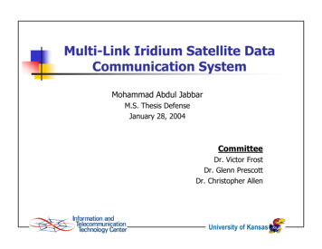
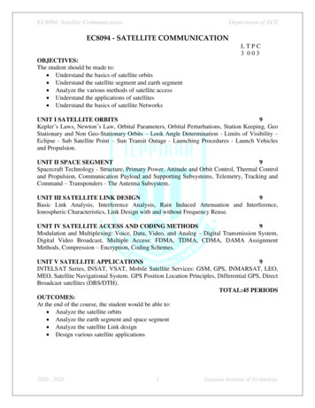
Geo-stationary satellites orbit along equator and remain stationary with respect to apoint earth, whereas the geo-synchronous satellites have an inclined orbit, resulting ina short visibility window at Poles. User equipment of both geo-stationary and geosynchronous consists of parabolic antennae of varying sizes pointed at an angle(called elevation angle) towards the satellite. Though parabolic antenna providesgood signal reception leading to a higher bandwidth connection, Mobile platformswould need tracking antennas, which may not be desirable in the Polar weatherconditions. Further, some of the user equipment might be too heavy for fieldapplications. The elevation angle and the received signal strength of these satellitesdecreases with increasing latitude. The connectivity is intermittent at higher latitudeand ceases to exist beyond certain latitude. As shown in figure 1.1, Polar Regions arenot serviced by these satellite systems. Though Inmarsat does have partial coverage inGreenland, most systems are not accessible beyond 70 degrees N or S latitude.Figure 1.1: Coverage map of Inmarsat (Source: [4])In recent years, a different system of satellite clusters known as Low Earth Orbitingsatellites or LEOs has been launched. Examples of LEOs include ORBCOMM,5
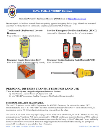
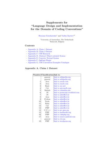
Iridium, Globalstar, ICO and Teledesic. The orbital period of these satellites is muchlower than that of earth. They are visible for a very short time from any given pointon earth. Hence, a number of satellites (48, in case of Globalstar) are needed toprovide continuous coverage to users.These LEO satellites are located at a relatively low distance (700-1000 km) fromearth. Each satellite covers a small area on the earth and provides connectivity forapproximately 10-30 minutes. A user on the land can place a successful call only ifboth the user and a land gateway lie in the coverage area of an overhead satellite.Hence the coverage is limited both by the number of satellites as well as number ofgateway. As seen in figure 1.2, most of the commercial LEO systems do not havefootprint/coverage in Polar Regions. The only exception is Iridium satellite system,which does provide coverage in Polar Regions and is dealt with later in this thesis.Figure 1.2: Coverage map of Globalstar (Source: [5])(Orange-primary, Yellow-extended, blue-very weak signal: sporadic connectivity)6
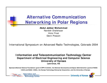
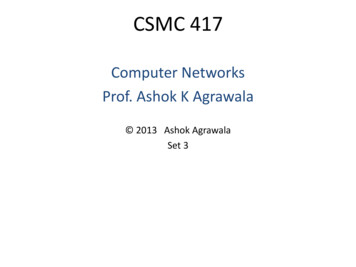
1.2.2 Special Purpose Satellite SystemsThe commercial satellite systems provide partial or no coverage in deep PolarRegions. So, the current data communication requirements are being met witheducational and research satellites. Special NASA and other government satellites arethe only broadband systems that can provide coverage in these regions. The currentsatellite systems being used by US Antarctic Program (USAP) at Poles [6] are ATS3,LES9, GOES, TDRS 1, and MARISAT2, which are either geo-stationary or geosynchronous satellite systems. ATS 3 and LES 9 are aging systems launched in 1967and 1976 respectively; ATS 3 is a voice only system where as LES 9 has limited datacapability and small visibility window of 5 hours (figure 1.3). Most of the data andInternet access from the science stations and field camps thus relies on special NASAsatellites GOES, TDRS 1 and MARISAT 2, which provide data connection withspeeds as high as 1 Mbps [1]. Since these satellite systems are geo-synchronous, theyhave a limited visibility window at Poles. Figure 1 shows various satellite visibilityperiods at South Pole Station during a typical 24-hour period.Figure 1.3: Typical South Pole satellite visibility (Source: [7])7
It is seen that total connectivity window is approximately 13 hours/day. Clearly, thereis lack of round the clock, lifeline data connection.Some of the other issues with the geo-stationary systems are that they have avery low elevation angle (about 1-4 degrees) from Poles, which combined with highaltitude of the satellites results in extremely large field equipment, e.g. antennas, thathas to be properly pointed towards the satellite. The GOES and TDRS 1 installationsat South Pole [8] use parabolic antennas of 10-meter radii built on large platforms.Though such installations provide high bandwidth, they cannot be used for numeroussmall field camps and science expeditions conducted each year at various locations inArctic and Antarctic. NASA has demonstrated the use of lighter mobilePORTCOMM (Portable Communications) terminals with TDRS satellite system atNorth Pole in April-May 1999 [9]. With an elevation angle of 0.8 degrees they wereable to achieve data rate of 4.8 kilobits per second. Higher bandwidths up to 1 Mbpsare possible with heavier TILT (TDRS Internet Link Terminal) systems that consumehigher power.1.2.3 Iridium Satellite SystemIridium is a low earth orbiting satellite system with 66 satellites in operation and 14spares in orbit. It has a true pole-to-pole coverage. The user equipment(phone/modem) is compact and light, comparable to that of an “old cell phone”.Detailed modem specifications are given in Appendix A. It is commercially availableand is easily accessible. Further, being a low earth orbiting system, Iridium requires8
less power and smaller (3.5-inch diameter) patch antennas, which do not need to bepointed in any particular direction. This is especially useful for mobile platforms as incase of PRISM project.Being the only satellite system that covers the entire globe, Iridium has received widesupport from numerous government organizations like DoD and NSF. In a specialcontract with Iridium, DoD bought an Iridium gateway in Hawaii and isexperimenting with the system for use in various research, education and defenseprojects. Ocean.US is coordinating a project with Omnet, Inc to explore the use ofIridium based data system for collecting ocean data from location where othersatellites do not provide coverage[10]. Due to the high costs and other technicalproblems involved in laying fiber or installing high-speed satellite stations, the SouthPole User’s Committee [2] has strongly recommended the immediate installation oflow-bandwidth Internet over Iridium for high priority data access and as a life linesystem at South Pole station.Iridium was initially designed as a voice only system. It can only provide a low datarate of 2.4 Kbps, which is not sufficient for any useful data transfer. Hence, there is aneed to develop a data communication system based on Iridium satellites, but with anincreased effective system capacity.9
1.3Project GoalsGiven that the maximum bandwidth of an Iridium link cannot exceed about 2.4 Kbps,one of the feasible options is to combine multiple channels to increase the effectivecapacity of the system. The goal of the project is to develop a moderate bandwidthsolution that can meet the communication needs of Polar research camps in generaland that of PRISM in particular. The specific objectives are as follows.1. Develop a data communication system to provide reliable datacommunication from Greenland and Antarctica to the Internet.2. System level design of a multi-channel Iridium data communicationsystem to increase the available bandwidth per application.3. Implement the system and conduct field experiments in Greenland.4. Evaluate the general performance and reliability of the system.5. Characterize the TCP/IP performance over a multi-channel Iridiumsystem.1.4Accomplishments A system level design of a scalable multi-channel system was developed. Multi-link point-to-point protocol was used to inverse-multiplex(combine) multiple Iridium satellite links in to a single logical channel ofaggregate bandwidth.10
Link management software that ensures fully autonomous and reliableoperation is developed. Also, an end-to-end network architectureproviding Internet access to science expeditions in Polar Regions isdemonstrated. A 4-channel system was implemented and field-tested at North GRIP,Greenland and experiments were conducted to determine the performanceand reliability of the overall system. Based on the analysis of data collected in the field experiments, the 4channel system was found to be over 90% efficient providing an averagethroughput of 9.2 Kbps. The system had an average system up time of 95% and a full capacity uptime of 80% and thus is reliable. Also, the mobile performance of thesystem is very similar to that of stationary systems. The system’s minimum round trip time of approximately 2 seconds wasfound to impair real time interactions. Hardware and software issues experienced in the field were captured andcorrective measures suggested.1.5Thesis OrganizationSince the work done is primarily based on the Iridium satellite system, it is discussedin detail in Chapter two along with the point-to-point protocol (PPP) and its extensionmulti-link point-to-point protocol (MLPPP), both of which are crucial to the project.11
Chapter three presents the complete system design, individual components of thesystem and its operation. The requirements, network architecture and the protocolstack are also discussed.The actual implementation of the system (in Linux) is detailed in Chapter four. Flowcontrol diagrams explaining the overall operation of the system are given. Individualsoftware blocks used for modem control and user authentication are also explained.The optimum link parameters and user authentication is also dealt here.Chapter five explains the tests conducted on the field (in Greenland) and the resultsobtained after data analysis. The system performance and reliability are clearlycharacterized. Further, an evaluation of TCP/IP performance over Iridium is given.12
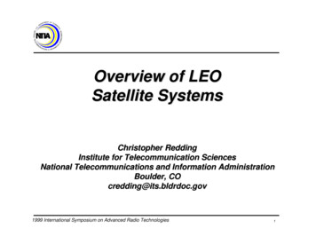
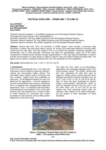
Chapter 2Background2.1Iridium Satellite SystemThe idea of a global satellite telephone network, involving a constellation of 77 LEOsatellites was first conceived in 1987 and named “Iridium” after the 77th element inthe periodic table. The final system was completed in May 1998 with an enhanceddesign consisting of 66 satellites only. The satellites are located at about 780 kmfrom ground, well above the residual atmosphere and below the Van Allen radiationenvironment, thus preventing it both from atmosphere and radiation effects withoutany shielding [17].Figure 2.1: Iridium satellite(Source: [14])The 66 satellites are arranged in six planes with near circular orbit inclined at 86.4degrees and containing 11 satellites each. These near polar orbits help to provide a13
true pole-to-pole coverage. Iridium satellite as shown in figure 2.1 weigh about 1500lb and have an expected lifetime of 5 to 8 years.2.1.1 ArchitectureThe LEO satellite system consists of a constellation of satellites that communicatewith users on one end and terrestrial gateways on the other end to complete a call.There are two distinct ways of designing a satellite-terrestrial network. Satellitesystems like Globalstar are designed on “bent pipe” or “single hop” architecture [15],where each satellite is just a radio repeater. The user’s signal bounces of the satelliteto a land station in the same footprint (beam spot) of the satellite. This architecturehas an inherent disadvantage that both the user and the gateway must be in thefootprint (coverage) of the same satellite for a successful data/voice call. Suchsystems need large number of costly earth stations all over the world for extensivecoverage. Hence such system usually do not have true global coverage, instead, theyconcentrate on major commercial landmasses. Seas, Oceans and Polar Regions arenot serviced.Another type of architecture, like that of Iridium, involves intelligent satellites wit
Multi-Link Iridium Satellite Data Communication System by Mohammad Abdul Jabbar Bachelor of Engineering, Electrical Engineering Osmania University, Hyderabad, India, 2001